26 minute read
SPARE LIST


First read carefully the Operating Instructions and the Safety Instructions. The machine may not be used before reading the instructions!
Operation of a new machine:
NOTE! The machine has been tested and adjusted by JUKO for the testing on the factory. The adjustments are average adjustments. In order to obtain the best possible results, make the adjustments suitable for your own needs before using the machine.
In a new machine the parts settle in place only after a couple of hours' work. Therefore the tightness of all screws, nuts and chains must be checked after 1-2 hours of work. The torque levels can be seen in Section 7.2.
Before further use for a new season:
CHECK:
- tyre pressure - condition of roller chains; change if needed - condition of bearings; change if needed - functions of feeding equipment by making a few turns with the calibration crank both on the fertilizer and seed units - springs of bottom flaps - worn coulters; repair or change if necessary - tightness of bearings of seed coulters; they should lower down by their own weight - level of oil in Optiseed; add if necessary -tightness of screws, nuts and chains - condition of hydraulic hoses and adaptors - functioning of area meter - lubrication and greasing of the machine - sliding of the feed tubes within each other by lifting each seed coulter. If there is friction in the telescope, disconnect the outer tube from the top and spray with silicone to improve sliding - functioning of the clutch
- Change broken parts if needed. - Order spare parts well before the following season. - When ordering spare parts, mention the model and serial number of the machine.
In order to guarantee safe operation of the machine, it must be used according to the Operating Instructions.
In operating the machine, the instructions as well as the prevailing conditions (temperature, moisture of the soil, etc.) must be taken into account. The adjustments are made on the basis of the conditions. Also make sure that the machine is ready for use (see Section 5.).
Read carefully the detailed operating instructions that follow.
6.1. MOUNTING THE DRILL TO THE TRACTOR
The drill is mounted on the tractor by the 3-point linkage and is fitted with category 2 linkage pins. The pins should be locked carefully and the side stabilisators of the draft links tightened.
The lowering speed of the tractor 3-point linkage should be adjusted to work slow enough to prevent too rapid lowering of the drill. If the lift are moved backwards on the draft links in order to provide more lift, the working position of the drill should be checked to ensure. that it can be lowered sufficiently to achieve correct sowing depth.
On some tractors with load control, a locking piece should be placed between the top link bracket and the lift frame to prevent the control mechanism to be damaged when using heavy machinery.
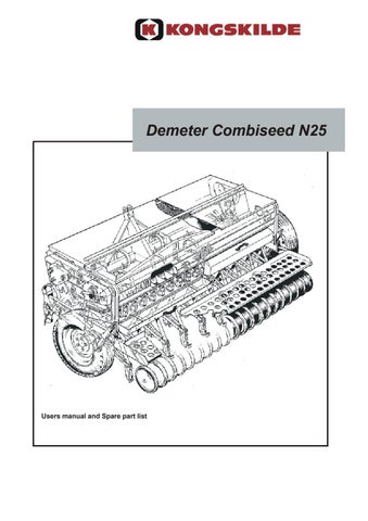
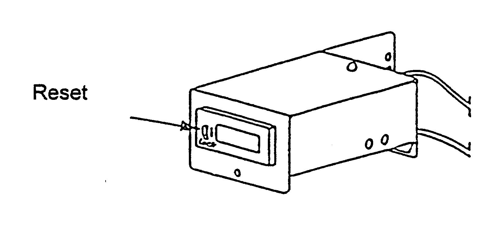
The drill is equipped with an electronic area meter. Hitch the area meter in a suitable place in the tractor cabin, where it easy to see it.
The meter has a accuracy of 0,1 are. For example the meter showing 10 is same as one are.
NOTE! Protected against wetness.
Connect the cable coming from the drill to the area meter. Connect the 7-point plug to the tractor.
NOTE! Keep the lights on when sowing.
Fig. 2. Display of the Area Meter
When the LED-light in the area meter is lightened, the area meter is on.
NOTE! Keep the reset button down when you are working, only keep it up when you are resetting.
Fig. 4 The area meter
When transporting the drill on public roads, all provisions of road traffic regulation as well as the special regulations of a slow vehicle must be observed.
If the warning triangle for slow vehicle and the head lights of the tractor are hidden behind the drill, they must be installed on the drill.
6.5. FILLING THE HOPPERS
There are different ways to fill the hoppers of the drill. The conditions and possibilities on the farm largely determine the method used.
The most commonly used methods:
1. Filling from small bags (e.g. 25 - 50 kg)
The bags can be stored on ground level, and lifted by hand and emptied into the hoppers. However, this is not to recommend, as it involves unnecessary work to lift the bags from the ground. By storing the bags on a platform or using a tractor trailer to bring the seed and fertilizer bags to the field, the filling is easy. The tractor with the drill is reversed close to the trailer (or lorry) placed at the edge of the field and the hoppers are filled standing on the footboard of the drill. The lifting height will then be very low. The trailer can also be used to take the bags to the part of the field to be sown.
2. Filling from large bags (e.g. 500 - 600 kg)
If a suitable crane or lifting device is available, the hoppers can be filled directly from the bags. Care should be taken not to work or pass under the lifted bag, as this can be dangerous. Also avoid to let the bag swing against the lid of the hopper as this can DAMAGE THE LID OR THE GAS SPRING OF THE LID. A safer way is to empty the large bags into a tractor trailer and use the methods suitable for bulk seed and fertilizer.
3. Filling with bulk seed and fertilizer
For handling of seed and fertilizer in bulk there are different ways. A high tipping trailer or a trailer with an auger are the best ways. A tractor with a front loader can also be used.
When filling the drill hoppers, care should be taken to prevent any foreign bodies, for instance pieces of paper or plastic bags, getting into the hopper. These can block the feeding units. The fertilizer sieve must be kept in place, especially if the fertilizer is lumpy or of inferior quality.
The feeding rates for seed and fertilizer are independently adjusted by changing the feed roller speed of rotation. Both the fertilizer and the seed unit have a stepless Optiseed rotation speed converter. In addition there is a cassette for the seed unit. This multiplies the ranges of settings by four and they can be chosen depending on the size of seed (Fig. 4).
Fig. 4. Optiseed rotation speed converter and cassette for seed.
Both seed and fertilizer unit feeder cases have shutters and bottom flaps. The shutters regulate the flow of fertilizer and seed to the feed rollers. If needed, some of the shutters can be closed completely if for instance the whole width of the drill is not used for sowing or if only every second seed coulter is used. The correct setting of the bottom flaps is important, as their distance to the feed roller influences the accuracy of feeding. The bottom flaps are spring loaded in case some foreigh body should pass between a bottom flap and a feed roller. This way damage to the feeder mechanism is prevented.
The settings for the feeder mechanisms are also given in calibration charts inside the fertilizer hopper lid.
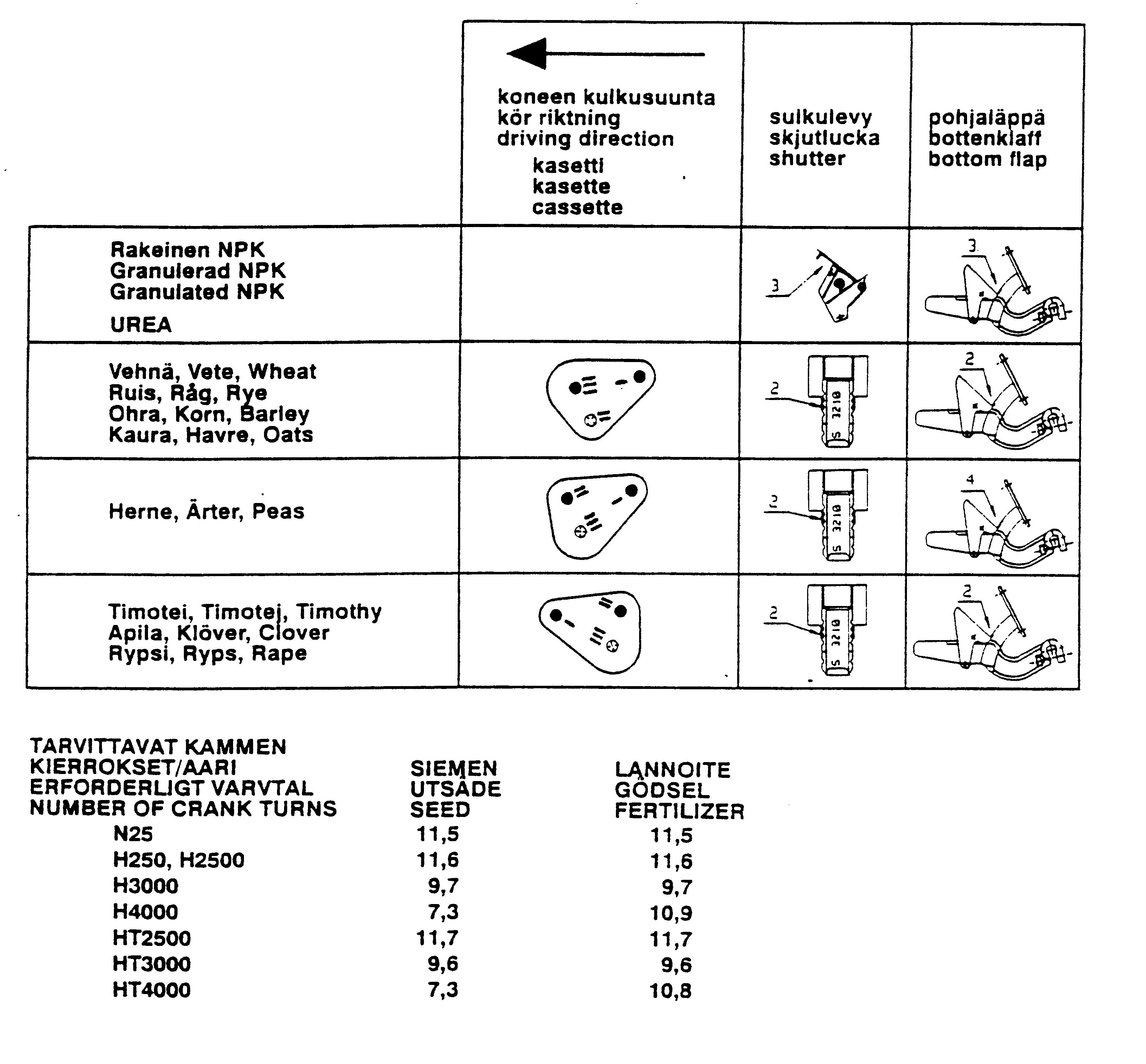
The fertilizer unit shutters (C) and bottom flaps (D) should be set as follows:
Granulated fertilizer Urea Shutters, Bottom flaps, position notch on arch segment 3 3
3 3
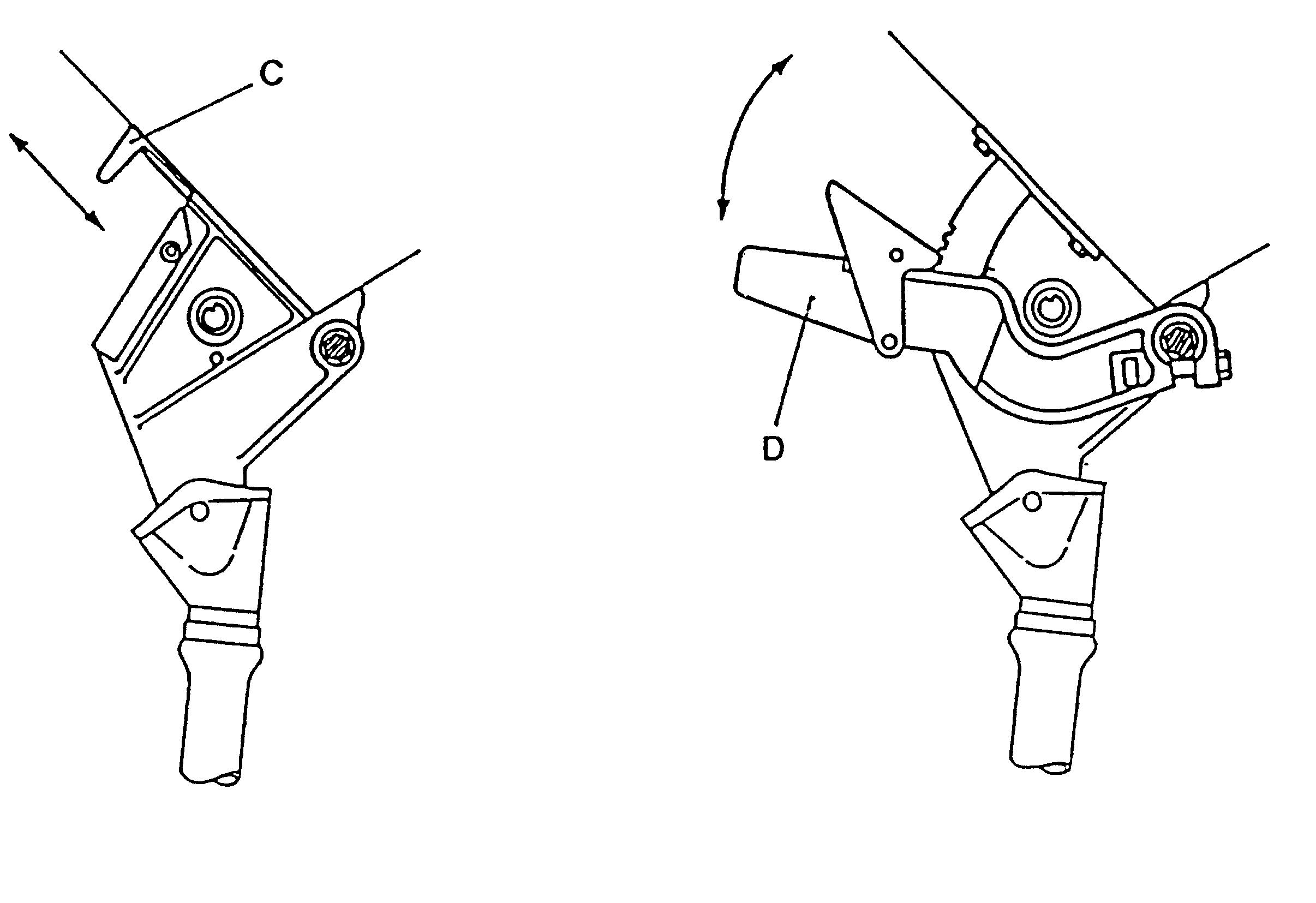
Fig. 5. Shutters and bottom flaps for the fertilizer unit.
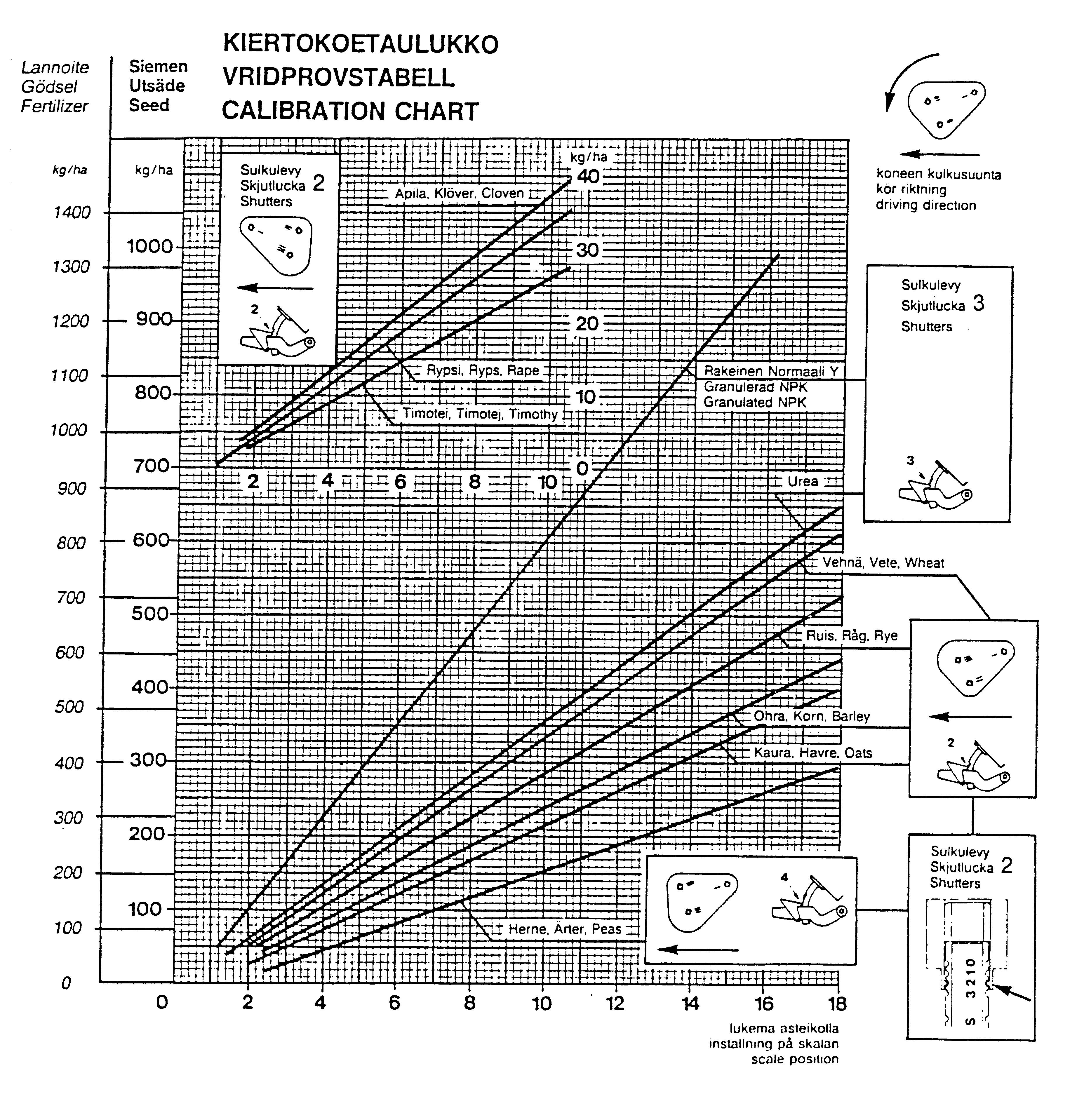
The fertilizer quantity is adjusted from the Optiseed rotation speed converter on the RIGHT HAND SIDE of the drill. The feeding rates for normal granulated NPK fertilizer and for urea are given in the calibration chart. The chart is, however, intended only as a guidance, as the feed rates vary depending on for instance size of granule and moisture of the fertilizer used. A calibration test should therefore always be made before commencing the sowing.
The seed unit shutters (E) and bottom flaps (F) should be set as follows:
Cereals Small seed Peas Shutters, Bottom flaps, position notch on arch segment 2 2
2 2
2 4
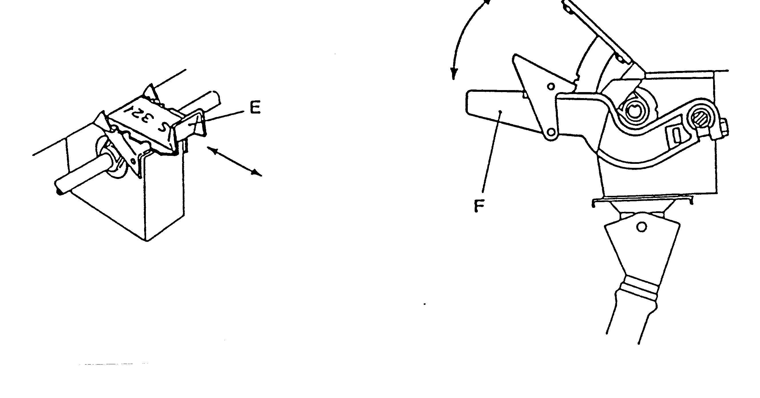
Fig. 6. Shutters and bottom flaps for the seed unit.
The seed rate is adjusted from the Optiseed rotation speed converter on the LEFT HAND SIDE of the drill. The settings and cassette positions for the following seeds are given in the calibration chart: wheat, rye, oats, barley, peas, rape, clover and timothy. Before sowing, the feeding rates should always be checked by making a calibration test. This is necessary, as seed rates can vary depending on for instance type, origin, humidity and size of the seed.
The feeding rates for both fertilizer and seed SHOULD ALWAYS BE CHECKED BY A CALIBRATION TEST. Fill the hoppers with seed and fertilizer. Check that the drill is in a horizontal position when standing on the ground.
The calibration test is carried out in the following way:
6.9.1. CALIBRATION TEST FOR SEED
A) Check that the setting for shutters, bottom flaps and cassette are the correct ones for the seed used. Adjust the lever on the Optiseed rotation speed converter according to the settings given in the calibration chart. Tighten the locking screw carefully.
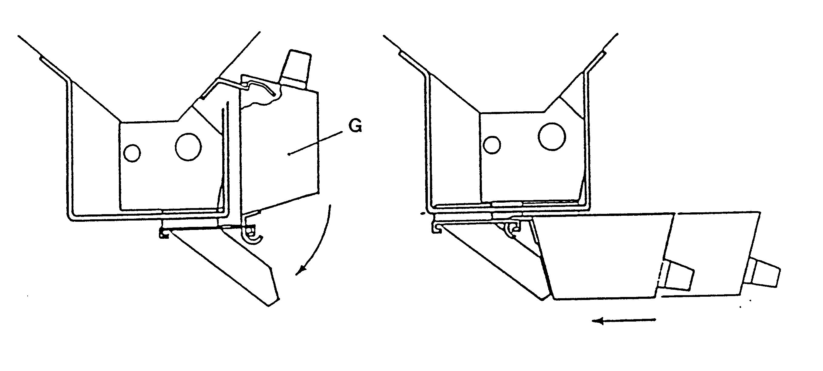
B) The seed unit has two calibration trays (G). Release them from the locking position by lifting from the handle and pulling back at the same time. Then let them down and push forward under the feeder cases. If the seed coulter pressure is very high, it should be decreased to allow the calibration trays enough room for the forward movement.
Fig. 7. Calibration trays
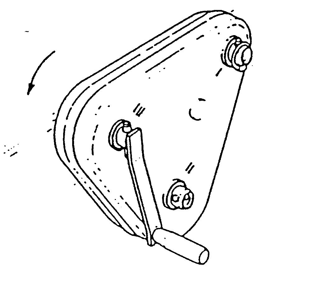
C) The two linch pins of the cassette are removed and the cassette is pulled out so much that it can be locked in the OUTER HOLE on the REAR AXLE using one of the linch pins. The calibration crank (to be found on the inner side of the hopper gable in front of the fertilizer hopper) is fastened to the FORWARD BUSH of the cassette and turned IN THE DIRECTION OF THE ARROW until the seed feeder units start to feed. Then the calibration trays are pulled back, removed and emptied back into the hopper.
Fig. 8. Calibration test for seed.
N25 (2,5 m) 11,5
E) The calibration trays are removed and the seed collected in them is weighed. The quantity is then multiplied by 100 to get the quantity for 1 hectare. If it is not the desired quantity, the lever on the Optiseed care is adjusted using the calibration chart as guidance. The calibration test should then be repeated.
F) After completing the calibration test the calibration trays are lifted back in sowing position. Observe that THE CASSETTE MUST BE PUSHED BACK IN SOWING POSITION AND LOCKED with linch pins.
G) The calibration test for seed can also be made the following way:
1. Check that the settings for the shutters, bottom flaps and cassette are the correct ones. Adjust the lever on the Optiseed rotation speed converter according to the settings given in the calibration chart.
2. Fill the seed hopper.
3. Push the calibration trays under the feeder cases to lock them. Drive in the sowing position until the seed feeder units start to feed. Open the locks by pushing the calibration tray forward and pushing both locks down. Pull the tray out and empty it.
4. Put the calibration trays back to the calibration test position. Drive the machine in the sowing position 40 m. Remove the calibration trays and weigh the seed collected in them. Multiply the quantity by 100 to get the quantity for 1 hectare. If it is not the desired quantity, the lever on the Optioned care is adjusted using the calibration chart as guidance. The calibration test should then be repeated.
5. When the calibration test is carried out by driving, observe that there may be changes in the feed rates because of the shaking of the machine or the sliding/slipping of the wheels.
A) Check that the settings for shutters and bottom flaps are the correct ones. Adjust the lever of the Optiseed rotation speed converter on the RIGHT HAND SIDE of the drill according to the settings given in the calibration chart. Tighten the locking screw carefully.
B) As there are no calibration trays for the fertilizer unit, lift the drill slightly off the ground and place a tarpaulin or plastic sheet under the fertilizer coulters to collect the fertilizer.
C) Remove the cassette on the LEFT HAND SIDE of the drill and fasten the calibration crank to the FRONT AXLE. Turn the crank IN THE DIRECTION INDICATED BY THE ARROW until all fertilizer feeder units start to feed. Pour the fertilizer from the tarpaulin back into the hopper and place the tarpaulin back in its place under the coulters.
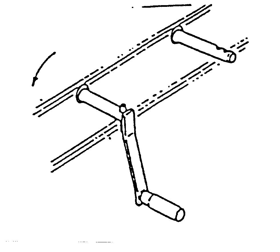
Fig. 9. Calibration test for fertilizer.
D) Turn the crank in the direction indicated by the arrow. The number of turns is the same as in the calibration test for seed (see above). This gives the quantity for 1/100 hectare.
E) The collected fertilizer is weighed and multiplied by 100 to get the quantity for 1 hectare (if all coulters are used for the test). If it is not the required, the lever setting of the Optiseed unit on the RIGHT HAND SIDE of the drill is adjusted using the calibration chart as guidance. The calibration test should then be repeated. After completing the calibration test for fertilizer, the CASSETTE MUST ABSOLUTELY BE PUT BACK IN the sowing position.
NOTE! NEVER use the area meter for calibration purposes. Too low TYRE PRESSURE WILL INCREASE the feed rates, so it must be checked regularly.
The correct pressure is:
245 kPa (2,5 bar)
CALIBRATION PROCEDURE FOR THE SEED UNIT
Remove the two linch pins locking the cassette. Pull out the cassette so much that it can be locked with a linch pin in the outer hole of the rear (cassette) axle. Use the calibration crank to turn the cassette from its forward bush in the direction indicated by arrow.
CALIBRATION PROCEDURE FOR THE FERTILIZER UNIT
Remove the cassette and turn the forward axle using the calibration crank in the direction indicated by arrow.
6.10. PLACEMENT DEPTH FOR FERTILIZER
The placement depth for fertilizer is adjusted by lifting or lowering the land wheels of the drill. The setting screws (H) are situated in the rear corners of the drill. They are fitted with scales (J) to help adjusting both wheels at the same level. This is very important as it assures uniform placement depth for all fertilizer coulters. NOTE THAT THE SCALES DO NOT INDICATE PLACEMENT DEPTH, they only provide comparison when adjusting the wheel position.
Research shows that the fertilizer should be placed 2 - 3 cm below seed level. For cereals the placement depth is normally 7 - 8 cm. In the field the depth should be checked by digging out the fertilizer in the fertilizer row.
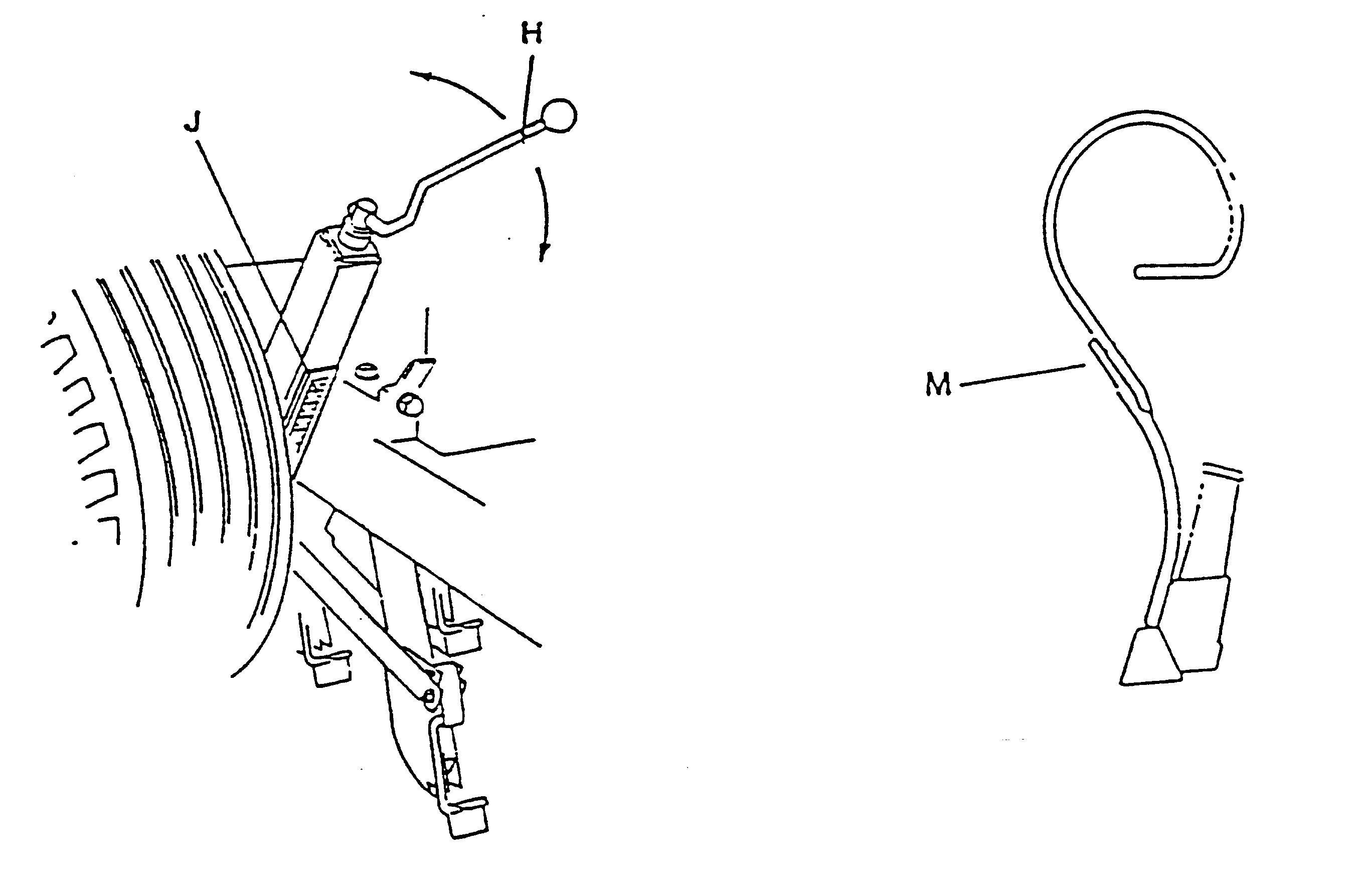
Fig. 10 a. Placement depth adjustment. Fig. 10 b. Removing the fertilizer coulters
Sowing without fertilizer coulters:
When sowing grass seed with the combination placement drill, using a cereal crop for protection, the cereal should be sown first and the fertilizer placed simultaneously. To sow the grass seed on the second run, the fertilizer coulters are removed by opening the nuts (M) and taking off the lower part of the coulters. Then the seed unit is set for grass seed. If there is fertilizer in the fertilizer hopper, the shutters of the fertilizer unit should be closed. When after the drilling the coulters are mounted back on the drill, care should be taken to ensure that the front coulters and the rear coulters are in the correct place.
The tip of the fertilizer coulters:
When the tip of the fertilizer coulters is worn down to the level of the side plates, they can be repaired by welding a tip replacement under the original tip. The tip replacement is an optional extra (part number 35431).
The sowing depth can be adjusted by changing the tightness of the tension springs (N). There are two different ways to do this:
Fig. 11 a. Central coulter pressure adjustment.
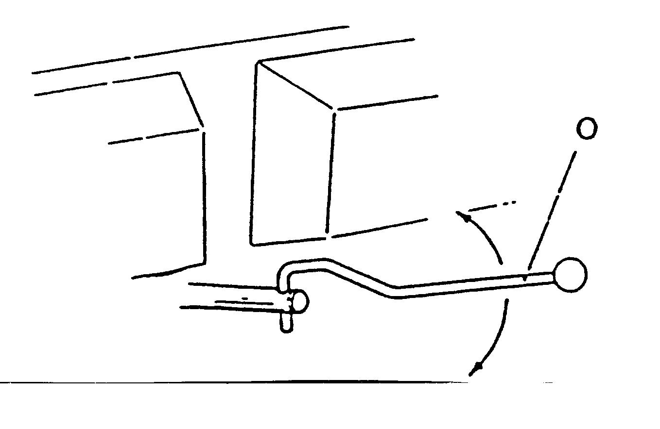
1. CENTRAL ADJUSTMENT
The tension of all springs is centrally adjusted using the adjusting screw (O) located under and behind the seed hopper. When the screw is turned counter clockwise, the tension of all springs increases and the coulters go deeper. If the screw is turned clockwise the depth of the coulters decreases.
Fig. 11 b. Individual coulter pressure adjustment.
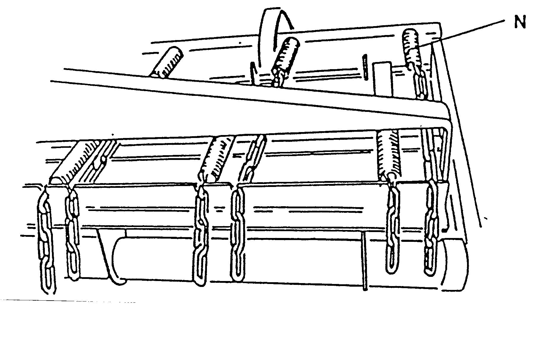
2. INDIVIDUAL COULTER PRESSURE ADJUSTMENT
The spring load of the coulters can be adjusted individually by tightening or loosening the adjusting chain of the springs. The coulter pressure for instance in the tractor wheel marks can this way be increased to achieve sufficient and even sowing depth.
The suitable sowing depth varies depending on soil, humidity and seed. For cereals the average sowing depth is 4 - 6 cm and for small seeds 2 - 4 cm. The aim should always be to place the seed in moist soil.
The general rule is that THE CULTIVATING DEPTH SHOULD BE THE SAME AS THE SOWING DEPTH. This way it is easy for the seed coulters to place the seed on the firm, moist soil in the border zone between cultivated and untouched soil. The sowing depth should always be checked by digging out the seeds in the seed row.
- The adhesive tape on the feed axle on the fertilizer unit can be used to see if the feeding is connected or disconnected.
- The area meter can be used to control the emptying of the hoppers. For instance, if you sow 500 kg of fertilizer per hectare and empty two large bags (1.200 kg) in the hoppers), one hopper will be enough for over 2 hectares.
- Blocking of fertilizer coulter can be checked through the window of the feed unit.
- Blocking of seed coulter can be checked by turning the calibration tray backwards to see into the funnels.
NOTE! The best way to avoid blocking of the coulters is to lower and lift the machine while moving forward.
NOTE! There is a shutter under the feed funnel that enables the lowering of the machine down when filling the hoppers.
NOTE! Do not let the drill move backwards when the coulters are down.
NEVER GO UNDER AN UNSUPPORTED DRILL!
- Always lift and lower the drill when it is moving forward. If this is not possible, for example in field comers, be careful that the coulters do not get blocked.
- Sowing can be done by driving around the field or by driving 3 - 4 rounds and then back and forth the straightest side. Both methods force you to turn the machine on a sown field. If you want to avoid this, the headlands can be sown last. Start sowing on a straight side and mark the headland width in the field. You can also estimate 2-4 width of the machine as headlands, where the drill can be easily turned. By sowing the headlands last you will have an even and untrampled sow.
- As the seed is placed on the border zone between cultivated and untouched soil, the field must be cultivated down to the sowing depth, and the cultivating soil must be even. This ensures successful sowing.
6.15. OTHER DRIVING INSTRUCTIONS
- The recommended sowing speed is 6-12km/h depending on the driving conditions.
NOTE! The driver is responsible for making sure that there are no people on top of the drill or at the danger zone when the drill is moving.
- Avoid sharp turns when the coulters are down.
- When reversing, always make sure there is enough ground clearance.
Proper maintenance will ensure that your drill operates smoothly and without stoppages during the busy sowing season.
1. Before commencing work, check that all screws and nuts are tightened according to Chart 1. Especially on a new drill the screws and nuts should be checked and tightened after a few hours' work.
2. Check the tyre pressure and make sure they correspond to those given in the the Technical Specifications.
3. The tightness of the wheel bolts must be checked regularly (see Operating Instructions for rims in Section 2).
4. Check and lubricate all bearings regularly.
Check, tighten and lubricate all chains regularly.
More detailed instructions on lubrication points and hours between lubrication are given in the Maintenance Instructions that follow (see next page). .
Use high quality greases and oils for lubrication. Follow the recommendations and instructions for their use.
5. Check the frame and other constrictions visually before the season to eliminate further damage by broken parts.
6. Clean the drill carefully after each use. This increases the reliability and service life of the drill. The drill can be cleaned using water under high pressure, but special care should be taken to avoid directing the jet on electric instruments and other parts that may be damaged (e.g bearings).
7. After the cleaning, lubricate all parts that may rust lightly with oil and let the machine idle for a while to spread the lubricants and remove water.
8. Paint the metal parts that have been worn in use.
9. During maintenance, make sure that lubricants and other oils or greases do not end up in the environment.
Proper maintenance and lubrication will ensure that your drill operates smoothly and without stoppages during the busy sowing season. On a new drill all screws and nuts should be checked and if necessary tightened after a few hours' work. The tyre pressure and the tightness of the wheel bolts should be checked regularly. Too low tyre pressure increases the feed rate. All roller chains should be checked from time to time and tightened if necessary.
Hours between lubrication can be seen in Chart 7.1. The chart gives the hours for normal work, in hard work the lubrication should be done more often.
Usually it is enough to pump once or twice through the grease nipple of the grease gun. JUKO machines have lubricated-for-life ball bearings, so they do not need much lubrication. Be careful when using a pneumatic grease gun, so that the bearing covers are not damaged.
The chains can be lubricated either with a brush or by immersing them in grease. Use a brush to grease parts that wear easily.
NOTE! The cassette does not need maintenance.
7.1. LUBRICATION CHART
Lubrication points
Fertilizer hopper:
Number of nipples Hours between lubrication
1. Feed shaft end bearing, right end of hopper ..............................................1...........................................20 2. Intermediate shaft, both ends of hopper ............................................. 2...........................................40 3. Gear/sprocket right end of hopper .............................................. 1...........................................20
Seed hopper:
4. Feed shaft end bearing, left end of hopper ................................................. 1.............................................40
Frame:
5. Adjusting frame sprocket, left side ................................................................ 1............................................20 6. Adjusting frame bearings, right and left end .................................................. 2.............................................20 7. Seed coulter adjusting bar bearings, under the hopper, in the rear ............................................................ 4............................................40 8. Coulter pressure adjusting screw nuts, under the hopper, in the rear ............................................................ 2.............................................40
The chart indicates lubrication points, number of nipples and hours between lubrication. High quality multipurpose grease should be used for lubrication. Care should be taken to ensure that the nozzle of the grease gun and the grease nipple on the drill are clean. Pump only once or twice, usually that is enough. Surplus grease is wiped off. Clogged and faulty nipples should be replaced.
The roller chains should be lubricated using clean SAE 20 lubrication oil. At the end of the sowing season, the chains should be removed and carefully cleaned with petrol. The chains should then be completely immersed in molte graphite grease. After this it is not necessary to lubricate the chains during the season.
7.2. TORQUE
If there are no other instructions elsewhere, use the following torque values when tightening screws. The torque values depend on the diameter and hardness of the screw (hardness is indicated in the head of the screw).
Torque Nm
Diameter mm
5 mm 6 mm Hardness
8.8 10.9 6 9 11 17 8 mm 28 40 10 mm 55 80 12 mm 95 140 16 mm 235 350 20 mm 475 675 24 mm 825 1170 30 mm 1630 2320
7.3. TYRE PRESSURE
Pressure 10.0x15.3 245 kPa (2,5 bar)
Fig. 12. Optiseed
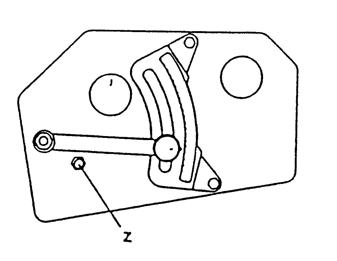
The Optiseed rotation speed converters do not need much maintenance. Occasionally check that the oil level is close to the rim of the filling opening (Z). The oil should be changed after every 500 hours of use. Remove the old oil through the filling opening (Z) either by sucking or loosening the Optiseed and turning it. Tighten the plug again and fill new oil to the rim of the filling opening (Z), using gear oil SAE 90. The capacity is approximately 0,5 litre. Possible repair should be done by the dealer or importer.
The screws (M8) that go through the cover of the Optiseed must be tightened carefully. The correct torque value is 1 kpm - 10 Nm. Overtightening the screw can make the cover to crack.
32
7.6. FERTILIZER COULTERS
The tip of the coulters should be changed when the difference between the tip and the sideplates is less than 5 mm. Worn coulters are easily blocked.
There are two ways to do this:
1. Remove the worn triangle-shaped tip by opening the seams of the lower part of the fertilizer coulter and sideplates and welding there the new tip (spare part no. 35427).
Fig. 13.
2. Weld the replacement tip (part. n:o 35431) right under the worn tip, when there is no need to remove the old tip. This method does not guarantee such durability for the coulters as in the first method, because welding heats up the replacement tip.
7.7. SEED COULTERS
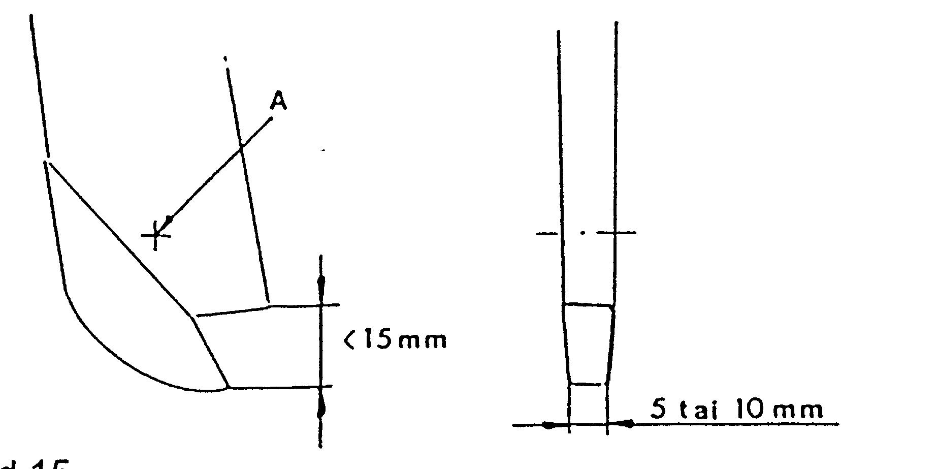
Sharpen the tip of the seed coulters when the width of the tip bottom is over 5 mm. Change the tip when the width of the bottom is over 10 mm or when the distance between the bottom of the tip and the lower edge of the funnel is below 15 mm.
The rivet (17) of the tip can be removed either by drilling or with a special tool (300430). To rivet the tip back, use either a hammer or the same special tool (300430) by changing the head.
Fig. 14 and 15.
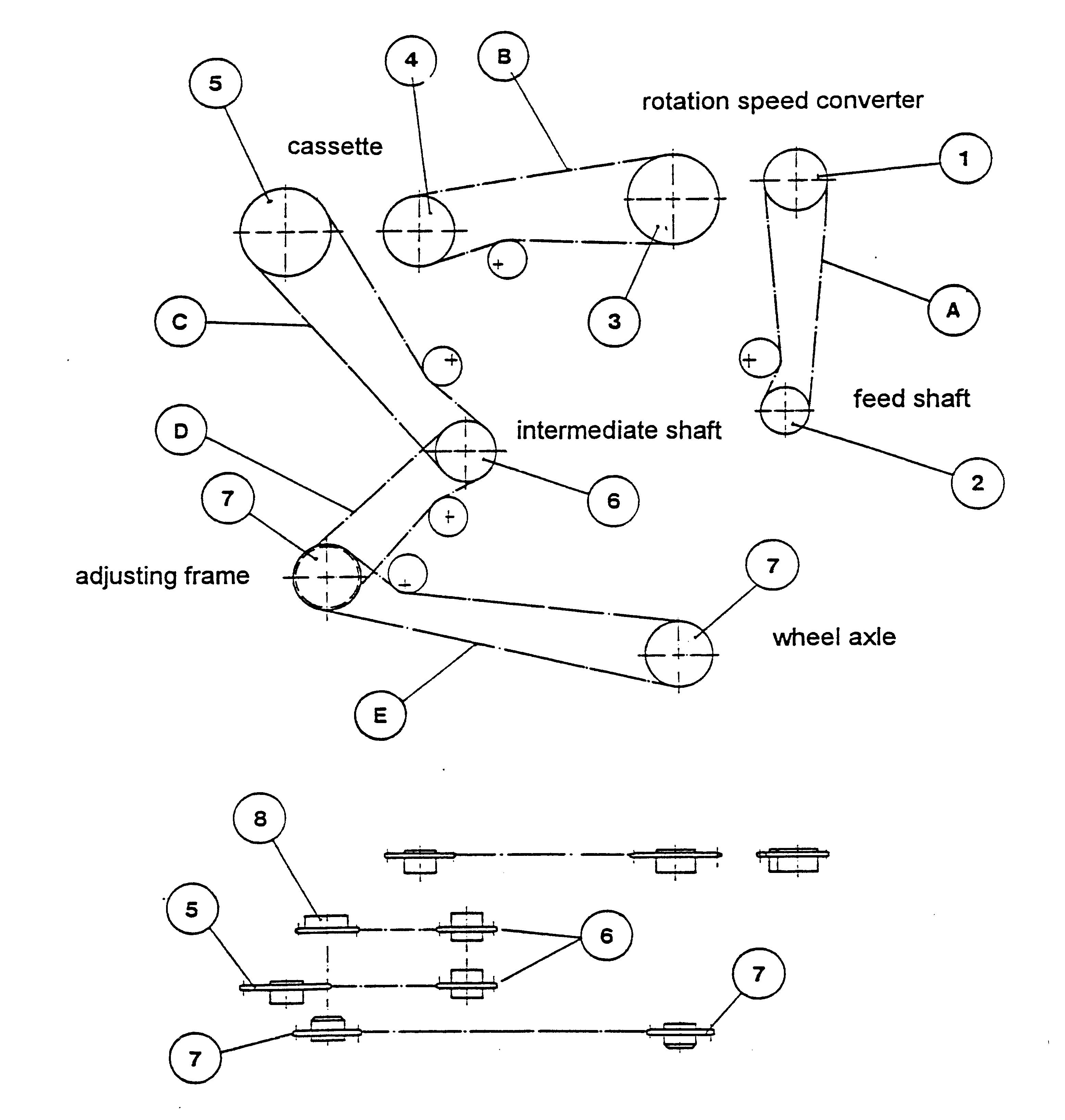
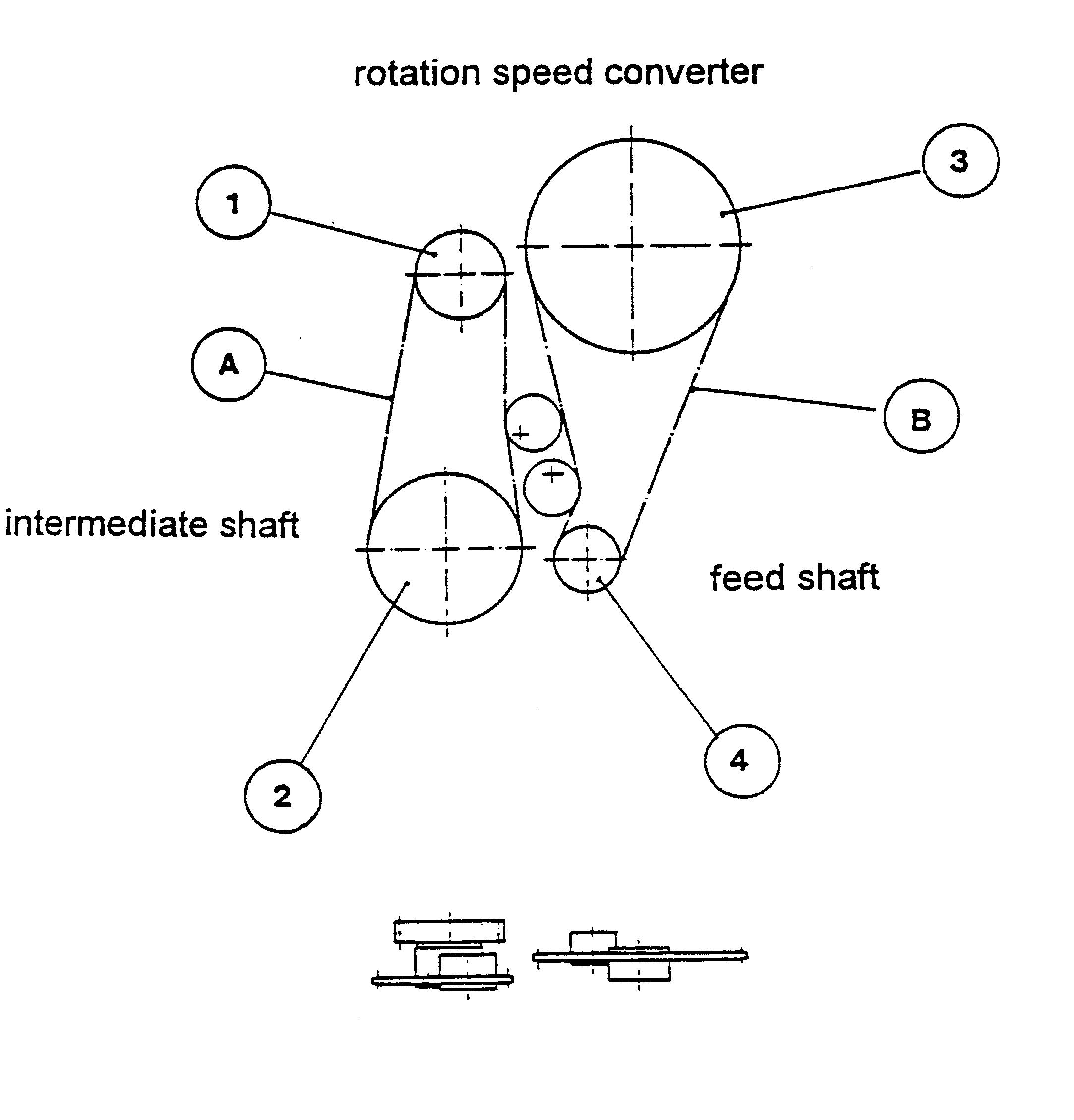
Sprockets:
1. 20524 Z=20 t=12,7 2. 30238 Z=15 t=12,7 3. 30237 Z=30 t=12,7 4. 31736 Z=24 t=12,7 5. 30237 Z=30 t=12,7 6. 32218 Z=20 t=12,7 7. 31955 Z=17 t=15,875 8. 31938 Z=21 t=12,7 Roller chains:
A. 1/2x5/16- 701. B. 1/2x5116- 86 1. C. 1/2x5/16- 891. D. 1/2x5/16- 59 1. E. 5/8x3/8- 671.
Sprockets:
1. 30238 Z=15 t=12,7 2. 32635 Z=36 t=12,7 3. 40258 Z=52 t=12,7 4. 30238 Z=15 t=12,7 Roller chains:
A. 1/2 X5/16- 69 l. B. 1/2x5/16- 83 l.
36
Before storing the machine should be carefully cleaned, lubricated and adjusted according to the instructions.
The tension of all strings should be released.
Part of the cleaning can be made using water under high pressure, but care should be taken to avoid directing the jet directly on the bearings and other parts that may be damaged by the pressure. All joints, chains etc. are maintained and lubricated.
Unpainted and uncovered metal parts that get worn out in use should be treated with oil for storing over the winter.
The drill should be stored under roof in a dry and dustless place. If this is not possible, the drill must be covered with a tarpaulin.
The drill must be emptied before storing.
STORING THE COMBINATION PLACEMENT DRILL
The combination placement drill should always be stored under roof in a dry place. After the sowing season the drill must be EMPTIED and thoroughly CLEANED of fertilizer, seed and soil. The cones of the fertilizer hopper are removed and cleaned. The machine can be cleaned using water under high pressure, but care should be taken to avoid directing the jet on the Optiseed boxes and bearings. After cleaning the maintenance work explained in section 7 should be undertaken. It is also advisable to oil the coulter tips to prevent corrosion.The area meter display box should be kept in a dry place. The drill should be checked before storing and any faults repaired well before the following season.
When ordering spare parts for the drill, always quote the serial number and type of the machine.
DISPOSAL, BREAKING UP AND RECYCLING
1. Disposal of hoses, oils as well as rubber and plastic parts should be carried out according to official regulations. 2. No special measures are needed to dispose of the metal parts. 3. Recycling of all material and parts is recommended.
The manufacturer, Oy Kongskilde Juko Ltd, grants to its products warranty, which is valid under following terms:
I Warranty period is one year from the date of delivery to the final customer, however,
This date of delivery should not be later than two years from the date of delivery from the manufacturer, or the following operated maximum acreages per one machine:
1. seed drills 200 ha
2. planters 100 ha
3. potato diggers
10 ha 4. potato harvesters 50 ha 5. sugar beet harvesters 75 ha/row 6. stone collecting machines 50 ha.
Which ever, year or acreage, comes first is applied.
II Warranty is valid also for spare parts which are supplied from Oy Kongskilde Juko Ltd or an authorized Juko dealer.
III Warranty covers material or manufacturing faults. In case an acceptable warranty, manufacturer will supply a new or an approvingly repaired part.
IV Warranty does not cover following: - damages caused by careless handling or storaging - damages caused by normal wearing - parts which are worn normally - undirect costs as standing costs, loss of income and loss of handled material caused by a failure covered by guarantee - all kind of losses caused by parts which are supplied from elsewhere than Kongskilde Juko Ltd or authorized Juko dealer - freight costs - repairing or travel costs
V Oy Kongskilde Kongskilde Juko Ltd will compensate warranty if: - damage has taken place in normal operation condition - instructions given by manufacturer have been followed - repairing work has been carried out by a person authorized by Kongskilde Juko Ltd or an authorized dealer of Kongskilde Juko Ltd - while repairing, original Juko spare parts have been used
VI A Warranty claim - all claims must be expressed to the dealer of the machine - damaged parts must be delivered to the dealer at the same time - a dealer will prepare a written warranty claim to the manufacturer and a damaged part must be sent to the manufacturer if requested - a warranty claim must be done within 30 days after damage
X-8052 Juko Control-control equipment 1865
X-6018A Rear harrow 1851
X-7021 Pressure rollers 1852
X-4001 Hopper extension 1810
X-5046 Additional hopper 1841
X-7022 Additional hopper, mounting kit. 1870