7 minute read
TRANSPORTATION

When transporting the machine, observe all related laws and regulations, and be careful to assure safety.
LOADING, UNLOADING WORK
WARNING
Loading or unloading the machine can be a dangerous operation, so be particularly careful. When loading or unloading the machine, run the engine at low idling and travel at low speed. Make sure the ramp has sufficient width, length and thickness to enable the machine to be safely loaded and unloaded. If the ramp sags appreciably, reinforce it with blocks, etc.
When loading and unloading the machine, park the trailer on a flat firm road surface. Keep a fairly long distance between the road shoulder and the machine.
Remove the mud from the undercarriage to prevent the machine from slipping to the side on slopes. Be sure the ramp surface is clean and free of grease, oil, ice and loose materials.
Never change the direction of travel when on the ramps. If it is necessary to change direction, drive off the ramps and correct the direction, then drive on to the ramps again.
Mechanical swing lock pin should always be engaged during transportation.
When turning the machine on the trailer, the machine’s footing is unstable, so carry out the operation slowly.
Always check that the door on the cab is locked, regardless of whether it is open or closed. Do not open or close the door on ramps or on a platform. This may cause a sudden change in the operating force.
When loading or unloading the machine with the automatic warming-up operation mode, if the automatic mode is released, the speed may change suddenly. Avoid loading or unloading during automatic warming-up operation.
When loading or unloading, always use ramps or a platform and carry out the operations as follows.
1. Properly apply the brakes on the trailer and insert blocks(2) beneath the tyres to ensure that it does not move. Then fix the ramps in line with the centres of the trailer and the machine. Be sure that the two sides are at the same level as one another.
Make the angle of the ramps (3) a maximum of 15°.
Set the distance between the ramps (A) to match the centre of the wheels.
2. Set the travel speed switch to the Lo position.
For details, see "HIGH/LOW SPEED SELECTOR SWITCH (93)"
(3)
(1)
(A)
3. Turn the auto-deceleration switch OFF, and return the fuel control dial (7) to reduce the engine speed.
For details, see "AUTO-DECELERATION SWITCH (100)"
4. Turn the swing lock switch (9) ON to apply the swing lock.
5. Set in the direction of the ramps, lower the work equipment as far as possible without letting it hit the trailer, then travel slowly to load or unload the machine.
When on the ramps, do not operate any lever other than the travel lever.
6. Load the machine correctly in the specified position on the trailer.
REMARK
When the work equipment is installed, load the machine from the front; when the work equipment is not installed, load the machine from the rear.
9 7
MIN
(2)
AD052900A
PRECAUTIONS FOR LOADING
WARNING
When loading the machine, park the trailer on a flat firm roadbed. Keep a fairly long distance between the road shoulder and the machine.
After loading to the specified position, secure the machine as follows.
1. Fully extend the bucket and arm cylinders, then slowly lower the boom.
2. Stop the engine and remove the key from the starting switch.
3. Raise safety lock lever to LOCK position.
REMARK
In certain conditions it may be possible for the safety lock lever to contact the left hand arm rest on the operator seat. to avoid this, always ensure that the left hand arm rest is stowed in the fully up position before operating the safety lock lever.
4. When transporting the machine, hold it down with chains or rope. Be particularly careful to ensure that the machine does not slip sideways.
NOTICE
When transporting the machine, place rectangular timber under one end of the bucket cylinder to prevent it touching the ground, thereby saving it from possible damage.
LOCK UNLOCK
HOW TO LIFT THE MACHINE
CAUTION
Personnel who perform lifting using a crane must be qualified.
WARNING
Contact your distributor to get instructions of lifting a machine. Some parts are required and are available as optional parts.
WARNING
Do not lift a vehicle with personnel in it.
The rope used for lifting must have sufficient strength to with stand the weight of this machine.
The machine must not be in a position other than that shown in the following procedure when lifting a vehicle. Otherwise, the machine may be unbalanced.
Lifting a machine must be performed on a flat place with the following procedure.
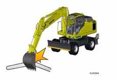
1. Start the engine and set the machine in the position shown in the figure at the right (boom at the top stroke end, arm bucket fully retracted). Direct the top revolving super-structure straight forward.
REMARK
When lifting a machine fitted with 2 piece boom you need to fully extend the adjust cylinder.
2. Engage mechanical swing lock.
3. Raise the safety lock lever to the LOCK position.
4. Stop the engine. Confirm safety around the operator seat. Get off the machine.
Be sure to close the cab door, windshield, right and left doors, engine hood, etc.

Lifting points
5. Mount a shackle to boom pins and the counter weight. Hang the wire rope.
6. The length off the wire rope and the lifting angle must be as shown in the figure on the right.
7. When lifting, make sure that there is no change in the position due to possible leakage in the hydraulic circuit on the boom cylinder head side.
8. When the machine leaves the ground, stop the machine and make sure sufficiently that the machine is balanced.
Then, lift the machine slowly.
PRECAUTIONS FOR TRANSPORTATION
WARNING
Determine the route for transporting the machine by taking into account the width, height and weight of the machine.
Always ensure mechanical swing lock is engaged
Always check that the door on the cab is closed and locked before transporting the machine. Always ensure machine covers/doors are closed and locked before transporting the machine.
NOTICE
Always retract the radio antenna, retract or remove the driving mirrors before transportation.
Obey all state and local laws governing the weight, width and length of a load. Observe all regulations governing wide loads.
Monoboom (with blade) Driving Position Transport Position
Arm Length (mm) ABCD
2100
2500
3000
8,365 3,240 8,410 3,200
(1) Height for transport = (D) Overall height + (3) height of trailer platform * Weights and dimensions: will vary according to specification. Consult your Komatsu distributor if in doubt.
Weight
15,375
15,410
15,540

Two Piece Boom (with blade)
Arm Length (mm) Driving Position Transport Position
ABCD Weight
2100 6000 4211 8188 3439 15,765
2500 5862 3978 8225 3208 15,800
3000 5878 3978 8211 3191 15,930
(1) Height for transport = (D) Overall height + (3) height of trailer platform
* Weights and dimensions: will vary according to specification.
Consult your Komatsu distributor if in doubt.

TRAVELLING POSTURE
Before starting to travel, be sure to raise and lock the outriggers, and raise the dozer blade.
Before travelling on public roads, the work equipment should be positioned as follows.
1. Position the upper structure so that it is facing the front of the undercarriage (the oscillation lock cylinders can be seen) and insert the swing lock pin.
2. Fully extend the bucket cylinder.
3. Fully extend the first boom cylinders.
4. Fully retract the second boom cylinders.
5. Adjust the arm cylinder such that the front of the arm is verticle.
6. Disable the work equipment levers by switching on the control lever lock switch.
7. Close manual lock valves
1) For the bucket cylinder, located on the arm.
2) For the arm cylinder, located on the first boom.
After setting the machine in the travelling posture, confirm that its overall height is below 4 m and that the distance between the centre of the steering wheel and the front of the work equipment is less than 3.5 m.
REMARK
This will necessitate removal of the bucket for machines fitted with 3.0 m arm.
Before moving off, lock all machine cover and toolbox doors to prevent accidental opening.