49 minute read
SERVICE PROCEDURE

INITIAL 250 HOURS SERVICE
Carry out the following maintenance only after the first 250 hours.
REPLACE FUEL FILTER CARTRIDGE
see “REPLACE FUEL FILTER CARTRIDGE” on page 218.
CHECK ENGINE VALVE CLEARANCE, ADJUST
see “CHECK & ADJUST VALVE CLEARANCE” on page 225. For details of the method of replacing or maintaining, see the section on EVERY 500 HOURS and 2000 HOURS SERVICE.
CHANGE OIL IN TRANSMISSION, HUBS + AXLES.
WHEN REQUIRED
CHECK, CLEAN AND REPLACE THE AIR CLEANER ELEMENT
WARNING
Never clean or replace the air cleaner element with the engine running.
When using pressured air to clean the element, wear safety glasses or goggles to protect the eyes.
Checking
If air cleaner clogging monitor flashes, clean the air cleaner element.
Cleaning or replacing the outer element
1. Open the machine door, loosen wing nut (2), then remove cover (6).
Remove wing nut, then take out element (7).
2. To prevent dirt or dust from entering, use tape or a clean cloth to cover the inner element of the air cleaner body.
3. Clean the air cleaner body interior and the cover.
4. Direct dry compressed air (less than 700 kPa (7 kg/cm²)) to element (7) from inside along its folds, then direct it from outside along its folds and again from inside.
Remove one seal from the outer element whenever the outer element has been cleaned.
Replace the outer element which has been cleaned 6 times repeatedly or used throughout a year. Replace the inner element at the same time.
Replace both inner and outer elements when the monitor lamp (3) flashes soon after installing the cleaned outer element (even if it has not been cleaned 6 times).
AD313740A
7
Check inner element mounting nuts for looseness and, if necessary, retighten.
5. If small holes or thinner parts are found on the element when it is checked by shining a light through it after cleaning, replace the element.
NOTICE
Do not use an element whose folds or gasket or seal are damaged. When cleaning the element, do not hit it or beat it against anything. Wrap up unused elements and store them in a dry area.
6. Remove the cloth and tape used for cover in Step 1.
7. Install the cleaned element and fix it with the wing nut.
8. If seal washer (4) is damaged or the thread of wing nut (2) is broken, replace it with a new part.
9. Remove vacuator valve (5) and clean with compressed air.
After cleaning, install again.
Replacing the inner element
1. Firsts remove the cover and the outer element, and then remove the inner element.
2. To prevent dust from getting in, use a clean cloth or tape to cover the air connector (outlet side).
3. Clean the air cleaner body interior, then remove the cover installed in Step 2.
4. Fit a new inner element to the connector and tighten it with the nuts. Do not clean and reinstall the inner element.
5. Install the outer element and fix it with the wing nut.

CLEAN INSIDE OF COOLING SYSTEM
WARNING
Soon after the engine has been stopped, the coolant is hot and can cause personal injury. Allow the engine to cool before draining water. Since cleaning is performed while the engine is running, it is very dangerous to enter the rear side of the machine as the machine may suddenly start moving. If the under cover is left removed, it may interfere with the fan. While the engine is running, never enter the rearside of the machine.
Never remove the radiator cap when the engine is at operating temperature. At operating temperature, the coolant is under pressure. Steam blowing up from the radiator could cause personal injury. Allow the engine to cool until the radiator filler cap is cool enough to touch with your hand. Remove the filler cap slowly to allow pressure to be relieved.
GENERAL
The cooling system operates under pressure which is controlled by the pressure relief valve in the radiator cap.
The belt-driven water pump circulates the coolant through the engine block, cylinder heads, radiator and engine oil cooler. Circulation is controlled by the thermostat which by-passes coolant flow around the radiator until the engine reaches operating temperature.
Proper cooling is possible only when the system is sealed, the radiator cap gasket is in good condition, the pressure relief valve and thermostat are operating properly. The system is free of coolant and air flow restrictions and the system is filled to the proper level.
Selection and maintenance of the engine coolant is important to long engine life. The following information provides recommendations for selecting the engine coolant, maintaining the coolant inhibitors and servicing the cooling system.
The system operates successfully with a water/antifreeze mixture or inhibited/conditioned water as the coolant. Water alone allows rust, scale deposits, and corrosion to occur within the system.
Every 2000 hours, the cooling system should be drained, flushed, and refilled as described in this section.
When deciding the ratio of antifreeze to water, check the lowest; temperature in the past, and decide from the mixing rate table given below.
It is actually better to estimate a temperature about 10°C lower when deciding the mixing rate.
Mixing rate of water and antifreeze
Min. atmospheric temperature
Amount of antifreeze
Amount of water º C -5 -10 -15 -20 -25 -30
liters 4.6 6 7.2 8.2 9.2 9.95
liters 15.4 14 12.8 11.8 10.8 10.05
WARNING
Antifreeze is flammable, so keep it away from any flame.
Use city water for the cooling water. If river water, well water or other such water supply must be used, contact your Komatsu distributor.
We recommend use of an antifreeze density gauge to control the mixing proportions.
WARNING
When removing drain plug, avoid pouring coolant on yourself.
REMOVAL
WARNING
Hot, scalding coolant can spray out if the radiator cap is removed suddenly. Relieve system pressure by slowly turning the cap to the first notch or lifting the safety lever (if equipped). Remove the cap only after the pressure is relirved.
Use extreme caution when adding coolant to the radiator to avoid being burned. Wear gloves and goggles and keep face away from the filler neck.
To remove the cap, turn the cap to the left, or counterclockwise up to the safety stop until the cap is free to be removed.
INSTALLATION
When installing the cap, the gasket and contacting surfaces must be clean. Turn the cap to the right, or clockwise until snug.
CHECKING COOLANT LEVEL
REMARK
Check the coolant level before starting the engine.
1. Check the coolant level in the radiator reserve tank (5). The coolant level should be between the FULL and LOW markings on the tank.
2. If coolant must be added, remove the reserve tank cap (4) and add coolant until level is between the FULL and LOW markings on the tank.
DRAINING THE SYSTEM
WARNING
Before working on the engine or electrical system, disconnect the negative (ground) battery cable. Tag the cable and controls to warn against starting. Wear hand and eye protection when draining hot fluids.
1. Run the engine until it reaches operating temperature; then stop the engine
2. Remove the radiator cap as outlined in this section.
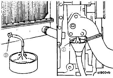
3. Remove the crankcase coolant drain plug located on the bottom of the coolant inlet (1).
4. Open the radiator drain valve (2).
5. Allow the system to completely drain into a suitable container.
Do not let drain outlets plug up during draining.
6. Close the radiator drain valve (2). Install the crankcase coolant drain plug (1).
CLEANING THE SYSTEM
At 2000 hours clean the cooling system as follows:
1. Drain the system into a suitable container. Refer to “DRAIN
ING THE SYSTEM” on page 196.
2. Drain and clean the reserve tank.
3. Close the radiator and crankcase drains. Full
Low

4. Fill the system with clean water, refer to “FILLING THE SYS
TEM” on page 197 and add a flushing compound that is compatible with aluminium. Flush the system in accordance with the instructions furnished with the compound.
5. After flushing, rinsing and completely draining the system.
Refill with clean coolant. Refer to“FILLING THE SYSTEM” on page 197.
FILLING THE SYSTEM
REMARK
Be sure to fill the heater and heater supply lines with fresh coolant, even if the heater is not in use (warm weather). Leaving the heater core empty causes corrosion in the heater.
1. Be sure the radiator drain valve and crankcase drain plugs are closed and tightened.
2. Fill the cooling system to maximum capacity. Fill with antifreeze.
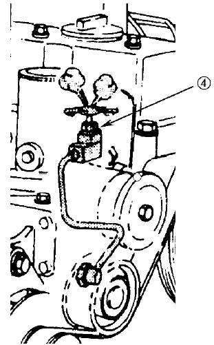
3. Open the after-cooler air drain valve (4) and add coolant until it overflows from the water filler. When the coolant comes up to near the water filler port, close the air drain valve.For coolant specifications, see COOLANT SYSTEM”.
4. Start engine and run until normal operating temperature is reached. Add coolant when needed to keep proper level in reserve tank.
5. After all air is removed and level remains fixed, install the radiator cap.
6. Fill the radiator reserve tank with coolant until level is between the FULL and LOW markings on the tank.
REFILLING AN OVERHEATED SYSTEM
Do not add coolant to the radiator of an overheated engine unless absolutely necessary. However, if necessary:
1. Remove the radiator cap. Refer to “RADIATOR CAP” in this section.
2. Be sure all the drains are closed.
WARNING
Use extreme caution when adding coolant to a hot radiator to avoid being burned. Wear gloves and goggles and keep away from the filler neck.
3. Add coolant to the radiator slowly until full.
4. Remove the reserve tank cap.
5. Add coolant to the reserve tank until the level is between
FULL and LOW marking on the tank.
6. When coolant level remains fixed between the FULL and
LOW on the reserve tank, install the reserve tank cap.
7. Run the engine
8. Stop the engine
9. Check for leaks and coolant level in the reserve tank.
CLEANING THE RADIATOR
Minor internal sludge accumulations will be removed when flushing the cooling system.
When internal accumulations are found that cannot be removed by normal flushing methods, consult your distributor.
Remove all bugs and dirt from the radiator core, using air or water under pressure. Direct the flow through the core, opposite to the normal direction of air flow.
CLEANING THE RADIATOR PRE-SCREEN
1. Remove the bolts retaining the radiator pre-screen and remove the pre-screen.
2. Clean the pre-screen with water under pressure.
3. Reinstall the pre-screen and retaining bolts.
THERMOSTATS
REMOVAL
1. Drain the cooling system. Refer to “DRAINING THE SYS
TEM” on page 196 in this section.
2. Remove the components and housing to access the thermostats.
3. Remove the thermostats and clean all gasket material from either mating surfaces.
INSTALLATION
1. Install two new thermostats with new gasket.
2. Re-install thermostat housing and all component parts.
3. Fill the cooling system. Refer to “COOLING THE SYSTEM” in this section.
FAN
WARNING
Personal injury can result from a fan blade failure. Never pull or pry on the fan. This can damage the fan blade(s) and cause fan failure.
Check the fan for cracks, loose rivets (for metal fans) and bent or loose blades. Make sure it is securely mounted. Tighten the capscrews if loose. Replace damaged fans.
CHECK AND TIGHTEN WHEEL NUTS
Order for tightening
Tighten the bolts in the order shown in the diagram. Torque to 450 Nm.
CHECK ELECTRICAL INTAKE AIR HEATER
Before the start of the cold season (once a year), contact your Komatsu distributor to have the electrical intake air heater repaired or checked for dirt or disconnections.
CHECK ALTERNATOR
GENERAL
The alternator requires no lubrication since its bearings are factory lubricated for life and require attention only at the time of major overhaul.
The alternator is equipped with an integral, transistorized voltage regulator. If the alternator fails to operate properly, consult your distributor.
PRECAUTIONS
NOTE:
The unit electrical system is negative ground. Be CERTAIN the ground polarity is correct when:


a. Installing a new battery.
b. Connecting a battery charger.
c. Using a booster.
Failure to observe proper polarity will result in damage to the alternator.
NEVER use a fast charger as a booster to start the engine.
NEVER unhook a battery terminal while the engine is running.
NEVER disconnect the alternator cable while the engine is running.
NOTE:
Do not short across or ground any terminals of the alternator. Do not connect any cable to the “R” terminal on the alternator. This will result in severe damage to the harness and radiator.
CHECK START MOTOR
Under normal operating conditions, no maintenance is required between engine overhaul periods. At the time of engine overhaul, the motor should be disassembled, inspected, cleaned and tested. Contact your distributor for detailed information.
REPLACE BUCKET SIDE CUTTERS
WARNING
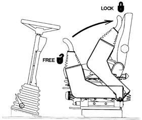
It is dangerous if the work equipment moves by mistake when the teeth are being replaced. Set the work equipment in a stable condition, then stop the engine and apply the control lever pad safety lock.
1. Untighten nuts (5) and bolts (3) and remove side cutters (1) and (2).
2. Clean cutter mounting face on bucket side plate.
3. Check nuts and bolts and replace if damaged.
4. Fit new side cutters.
5. Tighten bolts to 110 ± 10 kgm.
NOTE:
When side cutters are not being used shrouds (6) should be fitted to prevent wear of the bucket side plate.


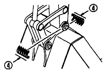
REPLACE BUCKET TEETH
Replace the teeth before the wear reaches the adaptor.
WARNING
It is dangerous if the work equipment moves by mistake when the teeth are being replaced. Set the work equipment in a stable condition, then stop the engine and apply the control lever pad safety lock.
NOTICE Please confirm with your bucket supplier for the correct procedure to replace bucket teeth and side cutters.
ADJUST BUCKET CLEARANCE
WARNING
It is dangerous if the work equipment moves by mistake when the clearance is being adjusted. Set the work equipment in a stable condition, then stop the engine and lock control lever pad safety lock.
1. Set the work equipment to the position shown in the diagram at right, stop the engine and set the safety lock lever to the lock position.
2. Shift 0-ring (1) of the linkage and measure the amount of play (a). Measurement is easier if you move the bucket to one side or the other so all the play can be measured in one place. (In the diagram this is on the left-hand side)
Use a gap (clearance) gauge for easy and accurate measurement.
3. Loosen the four plate fixing bolts of (2) and loosen plate (3).
Because it uses split shims, you can carry out the operation without removing the bolts entirely.
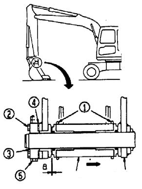
4. Remove shim (4) corresponding to the amount of play (a) measured above.
[Example] If the play is 3 mm, remove two sets of 1.0 mm shim (4 pieces) and 0.5 mm (2 pieces) and the play will become 0.5 mm. Four sets of 1.0 mm (8 pieces), two sets of 0.5 mm (4 pieces) are installed. Two pieces of shim makes one set.
When play (a) is smaller than one shim, do not carry out any maintenance.
5. Tighten the four bolts (2).
If the bolts (2) are too stiff to tighten, pull out pin stopper bolt (5) for easier tightening.
CHECK WINDOW WASHER FLUID LEVEL, ADD FLUID
If air is ejected with the window washer fluid, check the fluid level in window washer tank (1). If showing under the level, fill with automobile window washer fluid.

When adding fluid, be careful not to let dirt or dust get in.
Mixture ratio of pure washer fluid and water Since the ratio should be varied depending on atmospheric temperature, replenish washer fluid at the following mixture ratio, taking temperature into account.
Operation area and season Mixture ratio
Freezing temperature
Normal Pure washer 1/3: water 2/3 fluid - 10° C
Winter in cold region Pure washer fluid 1/2: water 1/2 - 20°C
Winter in extremely cold region Pure washer fluid - 30°C
Pure washer fluid comes in two types: for -10°C (for general use) and for -30°C (cold regions). Use pure washer fluid according to operation area and season.
CHECK AND ADJUST AIR CONDITIONER
CHECK LEVEL OF REFRIGERANT (GAS)
WARNING
If the liquid get into your eyes or on your hands, it may cause loss of sight or frostbite, so never loosen any part of the refrigerant circuit.
The air conditioning system is equipped with pressure switches
which disable the system if the pressure is too high or low, to prevent damage to the system.
a) Low pressure
i) Check for leaks. ii) Consult your distributor to recharge system.
b) High pressure
i) Check for blockages in piping.
Check in off-season
When not being used for a long period, operate the cooler for 3 to 5 minutes once a month to supply lubricant to each component of the compressor.
Inspection and maintenance items list for cooler
Inspection and maintenance items Contents Maintenance interval
Refrigerant (gas) Filling quantity Twice a year; spring and autumn
Condenser Clogging of fin Every 500 hours
Compressor Function Every 4000 hours
V belt Damage and tension Every 250 hours
Blower motor and fan Function (Check for normal sound) When required
Control mechanism Function (Check for function) When required
Piping for connection Installation condition looseness of tightening connection portion gas leakage, damage When required
DRAIN ENGINE BREATHER OIL CATCHER
Periodically drain oil from the engine breather catcher and whenever it is necessary to remove the engine undercover.
1. Remove plug (1) from engine undercover (3) and allow oil to drain out.
2. Replace plug (1).
Ensure that the breather hose (2) is positioned onto catcher reservoir whenever the undercover is removed.
CHECK BEFORE STARTING
CHECK COOLANT LEVEL, ADD WATER
WARNING
Do not open the radiator cap unless necessary. When checking the coolant, always check the radiator reserve tank when the engine is cold.
1. Open the rear door on the left side of the machine and check that the cooling water level is between the FULL and LOW marks on radiator reserve tank (1) (shown in the diagram on the right).
If the water level is low, add water through the water filler of reserve tank (1) to the FULL level.
2. After adding water, tighten the cap securely.
3. If the reserve becomes empty, first inspect for water leaks and then fill the radiator and the reserve tank with water.
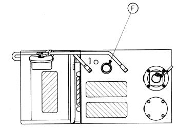
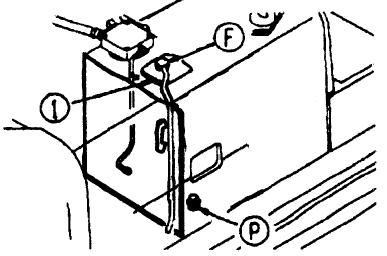
CHECK OIL LEVEL IN ENGINE OIL PAN, ADD OIL
1. Open the engine hood.
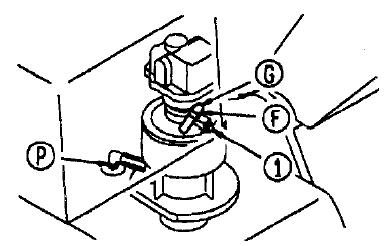
2. Remove dipstick (G) and wipe the oil off with a cloth.
3. Insert dipstick (G) fully in the oil gauge pipe, then take it out again.
4. The oil level should be between the H and L marks on dipstick (G). If the oil level is below the L mark, add engine oil through oil filler (F).
For details of the oil to use, “USE FUEL, COOLANT AND
LUBRICANTS ACCORDING TO AMBIENT TEMPERA
TURE” on page 177
5. If the oil is above the H mark, drain the excess engine oil from drain valve (P), and check the oil level again.
6. If the oil level is correct, tighten the oil filler cap securely and close the engine hood.
REMARK
Ensure that the machine is level when checking oil level.
G
AM090180
F
AD052340A
WARNING
Allow the engine to cool before checking the oil level to avoid burns by touching hot engine parts.
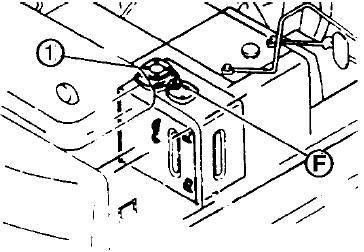
CHECK FUEL LEVEL, ADD FUEL
WARNING
When adding fuel, never let the fuel overflow. This may cause a fire. If spilling fuel, thoroughly clean up any spillage.
1. Use sight gauge (G) on the front face of the fuel tank to check that the tank is full.
2. If the fuel level is not within the sight gauge, add fuel through filler port (F) while watching sight gauge (G).
Fuel capacity: 240 l
For details of the fuel to use, see “USE FUEL, COOLANT AND LUBRICANTS ACCORDING TO AMBIENT TEMPERATURE” on page 177.
3. After adding fuel, tighten the cap securely.
REMARK
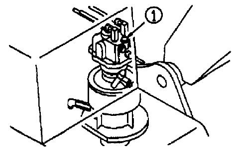
If breather hole (1) on the cap is clogged, the pressure in the tank will drop and fuel will not flow. Clean the hole from time to time.
CHECK OIL LEVEL IN HYDRAULIC TANK, ADD OIL
WARNING
When removing the oil filler cap, oil may spurt out, so turn the cap slowly to release the internal pressure before removing the cap. If oil has been added to above the H mark, stop the engine and wait for the hydraulic oil to cool down, then drain the excess oil from drain plug (P).
1. If the work equipment is not in the condition shown in the diagram on the right, start the engine run the engine at low speed, retract the arm and bucket cylinders, then lower the boom, set the bucket teeth in contact with the ground, and stop the engine.
2. Check sight gauge (G). The oil level is normal if between the
H and L marks.
NOTE:
Do not add oil if the level is above the H line. This will damage the hydraulic equipment and cause the oil to spurt out.
3. If the level is below the L mark, remove cap (F) from the hydraulic tank and add oil.
For details of the oil to use, see “USE FUEL, COOLANT
AND LUBRICANTS ACCORDING TO AMBIENT TEMPER
ATURE” on page 177. REMARK
The oil level will vary depending upon the oil temperature. Accordingly, use the following as a guide:
Before operation: around L level (Oil temperature 10 to 30°C)
Normal operation: around H level (Oil temperature 50 to 80°C).
CHECK AIR CLEANER FOR CLOGGING
1. Confirm that the air cleaner clogging monitor does not flash (1).
2. If it flashes, immediately clean or replace the element.
For details of the method of cleaning the element, see “CHECK, CLEAN AND REPLACE THE AIR CLEANER ELEMENT” on page 192.


1
AD313590A
CHECK ELECTRIC WIRING
WARNING
If the fuse blows frequently, or there are traces of short-circuiting in the electric wiring, always locate and repair the cause.
Check for damage of the fuse and any sign of disconnection or short circuit in the electric wiring. Check also for loose terminals and tighten any loose parts. Check the following points carefully.
Battery
Starting motor
Alternator
Please contact your Komatsu distributor for investigation and correction of the cause.
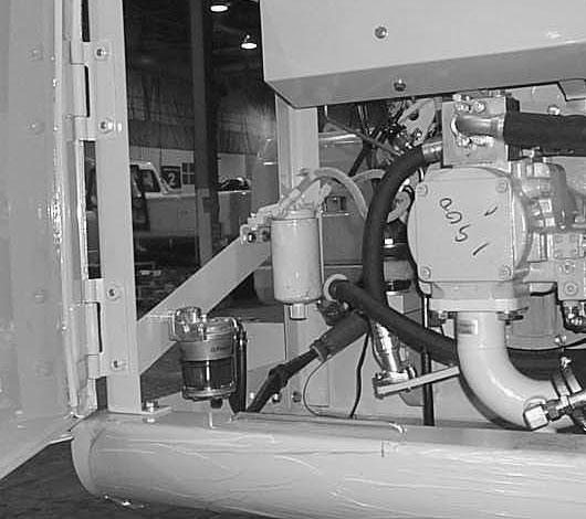
CHECK FOR WATER AND SEDIMENT IN SEDIMENTOR. DRAIN WATER AND SEDIMENT
A fuel sedimentor is mount in the radiator compartment and is accessed by the door on the left hand side of the machine. Entrapped sediment and water can be seen through the glass bow.
1. Loosen drain plug (1) and drain water and sediment until none is visible in bowl.
2. Tighten drain plug.
(A): Fuel
(B): Water/sediment
CHECK FOR WATER IN PRIMARY FUEL FILTER, DRAIN WATER
A primary fuel filter is fitted in the pump compartment. Drain the water from the primary fuel filter by turning cap at the bottom of the filter.
EVERY 50 HOURS
DRAIN WATER AND SEDIMENT FROM FUEL TANK
1. Carry out this procedure before operating the machine.
2. Prepare a container to catch the fuel that is drained.
3. Open valve (1) at the bottom of the tank and drain the sediment and water that has accumulated at the bottom together with fuel. When doing this, be careful not to get fuel on yourself.
4. When only clean fuel comes out, close drain valve (1).
NOTE:
Never use trichlene for washing the inside of the tank.
EVERY 100 HOURS SERVICE
Maintenance every 50 hours should be carried out at the same time.
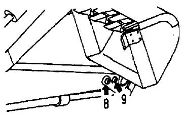
LUBRICATING
The minimum greasing interval is 100 hours, however more frequent greasing will be required depending on conditions/environment.
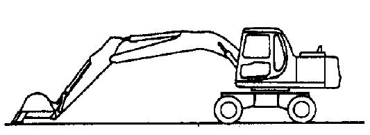
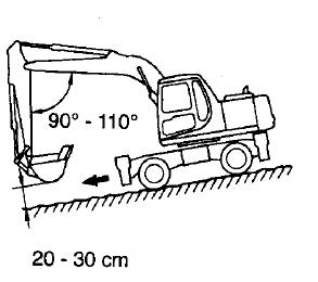
1. Set the work equipment in the greasing posture below, then lower the work equipment to the ground and stop the engine.
2. Using a grease pump, pump in grease through the grease fittings shown by arrows.

3. After greasing, wipe off any old grease that was pushed out.
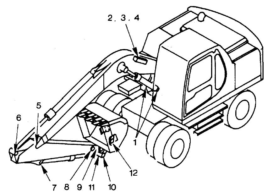
1. Boom cylinder foot pin (2 points)
2. Boom foot pin (2 points)
3. Boom cylinder rod end (2 points)
4. Arm cylinder foot pin (1 point).
5. Boom-Arm coupling pin (1point)
6. Arm cylinder rod end (1 point)


7. Bucket cylinder foot pin (1 point)
8. Arm-Link coupling pin (1 point)
9. Arm-Bucket coupling pin (1 point)
10. Link coupling pin (1 point)
11. Bucket cylinder rod end (1 point)
12. Bucket-Link coupling pin (2 points)
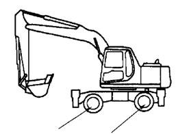
13. Outrigger cylinder foot pin (2 or 4 points)
14. Outrigger cylinder rod end (2 or 4 points)
15. Outrigger leg pivot (2 or 4 points)
16. Outrigger foot pivot (2 or 4 points)
17. Propshaft.


18. Boom adjust cylinder foot pin (1 point)
19. Boom adjust cylinder rod end (1 point)
20. Dozer blade cylinder rod end (2 points)
21. Dozer blade pivot pin (2 points)
22. Dozer blade cylinder foot pin (2 points)
23. Axle pivot (1 point)
24. Hub pivot (4 points)
25. Steer links (4 points)
26. Parallel link pivot pin (2 points)
27. Dozer blade cylinder rod end (2 points)
28. Single link pivot pin (2 points)
29. Dozer blade pivot pins (6 points).


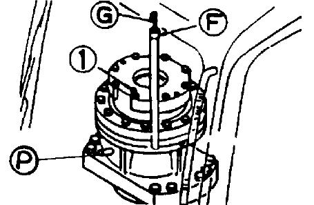
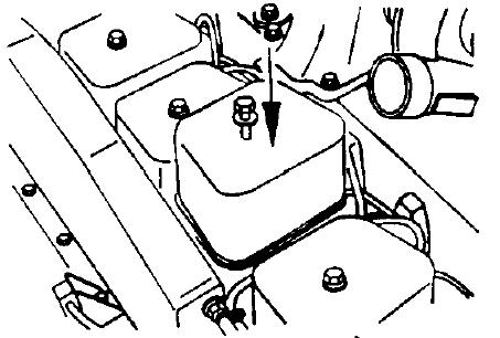
CHECK OIL LEVEL IN SWING MACHINERY CASE, ADD OIL
The oil is at high temperature immediately after the machine has been operated. Wait for the oil to cool down before carrying out this check.
1. Remove dipstick (G) and wipe the oil from the dipstick with a cloth.
2. Insert dipstick (G) fully in the guide.
3. When dipstick (G) is pulled out, if the oil level is between the
H and L marks of the gauge, oil level is proper.
4. If the oil does not reach the L mark on dipstick (G), add engine oil through dipstick insertion hole (F).
When refilling, remove bleeding plug (1).
For details of the oil to use, see “USE FUEL, COOLANT
AND LUBRICANTS ACCORDING TO AMBIENT TEMPER
ATURE” on page 177.
5. If the oil level exceeds the H mark on the dipstick, loosen drain plug (P) to drain the excess oil.
6. After checking oil level or adding oil insert the dipstick into the hole and install air bleeding plug (1).
CLEAN FRESH AIR INTAKE FILTER
1. Remove two wings nuts holding retaining strap (2).
2. Grasp filter element (3) centrally and pull out of housing.
3. Note that filter element is a sandwich of a fine filter and a coarse filter.
Clean filter by placing element in a mixture of hand hot water and neutral detergent with the coarse filter side downwards.
Move element up and down to release dirt. (A) Coarse (outside) (B) Fine (inside)
Rinse filter with clean water from the fine filter side.
4. Dry filter, compressed air may be used, but apply air from fine filter side.
5. Refit filter element ensuring coarse filter side is facing outwards.
NOTICE
The normal cleaning interval is 100 hours, however if the machine is used in a dusty environment, shorten this interval.
EVERY 250 HOURS SERVICE
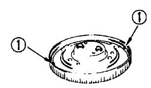
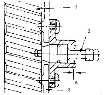
CHECK OIL LEVEL IN WHEEL HUBS, ADD OIL
Prepare a hexagonal wrench
1. Set so that plug (1) is at the horizontal position.
2. Remove plug.
3. If no oil emerges, turn hub so that hole is at the top and add oil.
4. Turn hub so that hole is horizontal.
5. Repeat steps 3 and 4.
For details of the oil to use see “USE FUEL, COOLANT
AND LUBRICANTS ACCORDING TO AMBIENT TEMPER
ATURE” on page 177.
6. After checking, install plug (1).


CHECK OIL LEVEL IN AXLES, ADD OIL
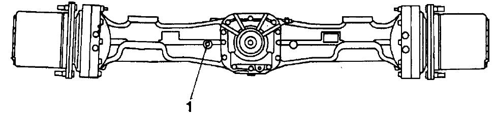
1. Ensure axle is horizontal and remove plug (1).
2. If no oil emerges attach tube and funnel and add oil until oil emerges from the hole after removing tube.
3. Replace plug (1).
For details of the oil to use, see “USE FUEL, COOLANT AND LUBRICANTS ACCORDING TO AMBIENT TEMPERATURE” on page 177.
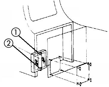
CHECK OIL LEVEL IN TRANSMISSION, ADD OIL
1. Remove level plug (2).
2. If oil emerges replace plug (2)
3. If no oil emerges remove plug (1) and add oil until oil emerges from plug hole (2).
4. Replace plugs.
For details of the oil to use, see “USE FUEL, COOLANT AND LUBRICANTS ACCORDING TO AMBIENT TEMPERATURE” on page 177.
CHECK LEVEL OF BATTERY ELECTROLYTE
WARNING
To avoid gas explosions, do not bring fire or sparks near the battery.
Battery electrolyte is dangerous. If it gets in your eyes or on your skin, wash it off with large amounts of water, and consult a doctor.
Carry out this check before operating the machine.
1. Open the battery door on the left side of the machine.
2. Remove cap (1), and check that the electrolyte is at the specified level (10 to 12 mm above the plate). If the electrolyte level is low, add distilled water to the specified level.
If the battery electrolyte is spilled, have dilute sulphuric acid added.
3. Clean the air hole in the battery cap, then tighten the cap securely.
When adding distilled water in cold weather, add it before starting operations in the morning to prevent the electrolyte from freezing.
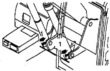
LUBRICATE SWING CIRCLE (2 points)
1. Lower the work equipment to the ground.
2. Using a grease pump, pump in grease through the grease fittings shown by arrows.
3. After greasing, wipe off all the old grease that was pushed out.
BELTS, GENERAL
WARNING
Before working on the engine or electrical system, disonnect the negative (ground) battery cable. Tag the cable and controls to warn against starting.
Replace badly worn, greasy or severely cracked belts immediately. These conditions prevent the belt from functioning correctly.
Prior to installing new belts, make sure all pulley grooves are clean and not worn. If a pulley is damaged or if the grooves are worn, it should be replaced.

All pulley support bearings, shafts and brackets must be in working order.
When replacing belts and pulleys, pulley alignment must be checked with belts tensioned and brackets securely clamped. A misalignment that can be detected by the naked eye is detrimental to belt performance.
During belt installation, do not force the belts into the pulley grooves by prying with a screwdriver on pry bar. This will damage the belt side cords which will cause the belts to turn and result in complete destruction of the belts in operation.
Belts on new machines and replacement belts lose their tension as they seat into the pulley grooves. Check the tension of new belts at 20 hour intervals until tension is stabilized and thereafter, every 250 hours. If the tension falls below the required minimum, the belt slips, and damages the belts and pulley grooves.
REMARK
When operating in abrasive conditions, check tension every 100 hours.
Visually inspect the belts for intersecting cracks. Transverse (across the belt width) cracks are acceptable. Longitudinal (direction of belt length) cracks that intersect with transverse cracks are not acceptable. Replace the belt if it is frayed or has pieces of material missing.
CHECK FAN BELT TENSION, ADJUST CHECKING TENSION
The engine is equipped with an automatic belt tensioner that maintains correct tension on the drive belt. To check belt tension a Gates type gauge must be used because of the wide drive belt. Proper tension should be 355 to 455 N.m gauge value.
If a Gates type gauge is not available, tension may be checked by belt deflection. Press the belt with your finger at the longest span and measure the deflection. Maximum deflection 9.5 to 12.7 mm.
ADJUSTING
With the automatic belt tensioner, no adjustment is required.
REPLACEMENT
To replace the drive belt, place a 3/8 in. drive rachet (2) in the 3/8 in. square drive hole in the belt tensioner. Push the rachet “UP” to loosen the tensioner. Remove the old belt (1). Inspect belt tensioner. The tensioner pulley should spin freely with no rough spots detected under hand pressure. Install the new belt.
CHECK ALTERNATOR AND WATER PUMP BELT TENSION, ADJUST CHECKING TENSION
The engine is equipped with an automatic belt tensioner that maintains correct tension on the drive belt. To check belt tension a 2 1

“Gates” type gauge must be used because of the wide drive belt. Proper tension should be 355 to 455 N.m gauge value.
If a “Gates” type gauge is not available, tension may be checked by belt deflection. Press the belt with your finger at the longest span and measure the deflection. Maximum deflection 9.5 to 12.7 mm.
ADJUSTMENT
With the automatic belt tensioner, no adjustment is required.
REPLACEMENT
To replace the drive belt, place a 3/8 in. drive rachet in the 3/8 in. square drive hole in the belt tensioner. Push the rachet “UP” to loosen the tensioner. Remove the old belt. Inspect belt tensioner. The tensioner pulley should spin freely with no rough spots detected under hand pressure. Install the new belt.
NOTE:
The belt tensioner is spring loaded and must be pivoted away from the belt. Pivoting in the wrong direction can result in damage to the belt tensioner.
CHECK AND ADJUST TENSION OF AIR CONDITIONER COMPRESSOR BELT
Testing
The belt should deflect 14-16 mm when pressed with a finger force of approx. 6 kg at a point midway between the crankshaft pulley and the compressor pulley.
Adjusting
1. Loosen 2 bolts (1) and 2 bolts (2), and move compressor (3) to adjust.
2. When the deflection is correct, tighten bolts (1) and (2) to hold the compressor in position.
3. Check each pulley for damage, and check the V-groove and
V-belt for wear. In particular, check that the V-belt is not contacting the bottom of the V-groove.
4. If the V-belt is streched and cannot be adjusted any further, or if there are any cuts or cracks, replace the V-belt.
5. After replacing the V-belt, adjust again after one hour of operation. Compressor pulley
14 – 16 mm
Crankshaft pulley
AM096280A
EVERY 500 HOURS SERVICE
Maintenance for every 50, 100 and 250 hours should be carried out at the same time.
REPLACE FUEL FILTER CARTRIDGE
WARNING
Engine is at high temperature immediately after the machine has been operated. Wait for engine to cool down before replacing the filter.
Keep naked flames - sparks away from fuel.
When cranking the engine, ensure all safety procedures have been followed, as the engine may start.
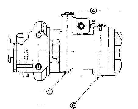
FUEL FILTER IS LOCATED IN THE PUMP COMPARTMENT
Get a filter wrench and a container to catch the fuel.
1. Set the container to catch the fuel under the filter cartridges.
2. Using a filter wrench, turn filter cartridge (1) counterclockwise to remove them.
3. Clean the filter holder, fill new filter cartridge with clean fuel, coat the packing surface with engine oil, then install it to the filter holder.
4. When installing, tighten until the packing surface contacts the seal surface of the filter holder, then tighten it up 1/2 to 3/4 of a turn.
If the filter cartridge is tightened too far, the packing will be damaged and this will lead to leakage of fuel. If the filter cartridge is too loose, fuel will also leak from the packing, so always tighten to the correct amount.
5. After replacing the fuel filter cartridge, bleed the air from the system.
Fuel System
Bleeding
Controlled venting is provided at the injection pump through the fuel drain manifold. Small amounts of air introduced by changing the fuel filters or fuel injection pump supply line will be vented automatically, if the fuel filter is changed in accordance with the instructions. No manual bleeding of fuel lines is required.
NOTE:
Manual bleeding is required if:
The fuel filter is not filled prior to installation.
Fuel injection pump is replaced. 1
High pressure fuel line connections are loosened or fuel lines replaced.
Initial engine start up or start up after an extended period of no engine operation.
Vehicle fuel tank has been run until empty.
Low Pressure Lines and Fuel Filter(s)
Venting
1. Open the bleed screw
2. Operate the plunger on the lift pump until the fuel flowing from the fitting is free of air.
Tighten the bleed screw. Torque Value: 9 N•m
CAUTION
When using the starting motor to vent the system, do not engage it for more than 30 seconds at a time: Wait two (2) minutes between engagements.
WARNING
It is necessary to put the engine in the “ON” position. Because the engine may start, be sure to follow all the safety precautions. Use the normal engine starting procedure.
Heat Off
On
Start
AM090710A
High pressure Lines
Venting
WARNING
The pressure of the fuel in the line is sufficient to penetrate the skin and cause serious bodily harm.
1. Loosen the fittings at the injectors, and crank the engine to allow entrapped air to bleed from the lines. Tighten the fittings.
Re- Tighten Line Fittings Torque Value: 30 N•m
WARNING
Do not bleed a hot engine as this could cause fuel to spill onto a hot exhaust manifold creating a danger of fire.
2. Start the engine and vent one line at a time until the engine runs smoothly.
CHECK SWING PINION GREASE LEVEL, ADD GREASE
Prepare a scale.
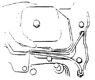
1. Remove bolts (1) (2 bolts) on the top of the revolving frame and remove cover (A).
2. Check the colour of the grease. If it is milky white, it is necessary to change the grease. Please contact your Komatsu distributor.
The total amount of grease is 33 L (29.7 kg).
3. Insert a rule into the grease and check that the depth of the grease is at least 25 mm. Add more grease if necessary.
4. To add more grease replace cover (A) and (1) bolts (2 bolts), remove bolts (2) (2 bolts) on the top of the revolving frame and remove cover (B). Add more grease.
5. Replace cover (B) with bolts (2).
AM091710A
CHANGE OIL IN ENGINE OIL PAN, REPLACE ENGINE OIL FILTER CARTRIDGE
WARNING
The oil is at high temperature after the engine has been operated, so never change the oil immediately after finishing operations. Wait for the oil to cool down before changing it.
Prepare the following
Container to catch drained oil: Min. 17 litres
Refill capacity: 16 litres
Filter wrench
1. Remove the inspection cover of the undercover directly under drain valve (P) under the machine, then place a container to catch the oil.
2. Remove cap from drain valve (P), fit drain hose from machine toolkit and drain oil. After draining oil remove hose and refit cap.
3. Check the drained oil, and if there are excessive metal particles or foreign material, please contact your distributor.
4. Tighten drain valve (P).
5. Using the filter wrench, turn filter cartridge (1) counterclockwise to remove it.
In particular, if this operation is carried out immediately after stopping the engine, a large amount of oil will come out, so wait for 10 minutes before starting the operation.
6. Clean the filter holder.
REMARK
Confirm that no remnants of old packing still adhere to the filter holder as this may result in oil leakage.
NOTICE
Do not tighten filter or use any tools for installation be cause this can damage the gasket and filter.
7. Fill the new filter with clean oil.
8. Install the new filter by applying a little engine oil to the seal and thread the filter on by hand by turning it clockwise until hand tight.
9. After replacing the filter cartridge, add engine oil through oil filler (F) until the oil level is between the H and L marks on dipstick (G).
For details of the oil to use, see “USE FUEL, COOLANT AND LUBRICANTS ACCORDING TO AMBIENT TEMPERATURE” on page 177.
G F

NOTICE
Even if the machine has not been operated for 500 hours, the oil and filter cartridge must be replaced when the machine has been operated for 6 months. In the same way, even if the machine has not been operated for 6 months, the oil and filter cartidge must be replaced when the machine has been operated for 500 hours.
CLEAN AND INSPECT RADIATOR FINS, AFTER COOLER FINS, OIL COOLER FINS AND CONDENSER FINS (ONLY FOR MACHINES EQUIPPED WITH AIR-CONDITIONER)
WARNING
If compressed air, steam, or water hit your body directly, there is danger of injury. Always wear protective glasses, mask, and safety shoes.
1. Remove the engine hood and open rear door on the left side of the machine. Loosen bolts (1) and remove the radiator front cover.
2. Blow off mud, dust or leaves clogging the radiator fins and oil cooler fins using compressed air.
At the same time, clean the net in front of the oil cooler. Clean the condenser fins on machines equipped with the air conditioner. The condenser is located on the front of the radiator.
Steam or water may be used instead of compressed air.
3. Check the rubber hose. Replace with a new one if the hose is found to have cracks or to be hardened by ageing.
Further, check hose clamps for looseness.
NOTICE
To prevent damage to the fins, apply compressed air from an appropriate distance. Damaged fins may cause water leakage or overheating. In a dusty site, check the fins daily, irrespective of the maintenance interval.
1

1
REPLACE HYDRAULIC TANK BREATHER ELEMENT
WARNING
Wait for the oil to cool down before replacing the breather element. When removing the oil filler cap, turn it slowly to release the internal pressure, then remove it carefully.
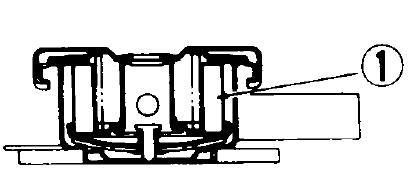
1. Remove the cap of oil filter (F).
2. Replace element (1) inside the cap with a new one.
REPLACE HYDRAULIC FILTER ELEMENT
WARNING
When removing the oil filler cap, turn it slowly to release the internal pressure before removing it.
1. Remove the cap from oil filler (F), and release the internal pressure.
2. Loosen 4 bolts, then remove cover (1).
When doing this, the cover may fly out under the force of spring, so hold the cover down when removing the bolts.
3. After removing spring (2) and valve (3) take out element (4).
4. Clean the removed parts in diesel oil.
5. Install a new element in the place where old element (4) was installed.
6. Set valve (3) and spring (2) on top of the element.
7. Set cover (1) in position, push it down by hand, and install the cover with the mounting bolts.
8. Screw in the oil filler cap and install the cover.
9. To bleed the air, start the engine according, see “STARTING
ENGINE” on page 113. and run the engine at low idling for 10 minutes.
10. Stop the engine.

REMARK
Operate the machine after halting for more than 5 minutes to eliminate bubbles in the oil inside the tank.
11. Check for oil leakage and wipe off any spilled oil.
When the hydraulic breaker is installed, the hydraulic oil deteriorates earlier than in normal bucket digging work.
The first element replacement should be at 100 to 150 hours for new machines. Thereafter, replace the element according to the table on the right.
EVERY 1000 HOURS SERVICE
Maintenance for every 100, 250 and 500 hours should be carried out at the same time.
CHANGE OIL IN SWING MACHINERY CASE
WARNING
The oil is at high temperature immediately after the machine has been operated. Wait for the oil to cool down before carrying out maintenance.
Container to catch drained oil: Min. 2.5 l capacity
Refill capacity: 2.5 l
1. Set an oil container under drain plug (P) under the machine body.
2. Loosen drain valve (P) under the body, drain the oil, then tighten (98 - 185 Nm (10-19kgm)) the drain valve again.
3. Remove dipstick (G) and bleeding plug (1).
Add the specified amount of engine oil through gauge hole (F).
For details of the oil to use, see “USE FUEL, COOLANT AND LUBRICANTS ACCORDING TO AMBIENT TEMPERATURE” on page 177.
Replacement interval (H) Replacement interval for hydraulic oil
(When not Breaker operation (ratio %) Hydraulic Filler element using breaker) AD31373D (When using breaker only
4. After refilling, install bleeding plug (1).
5. Wipe off oil on the dipstick with a cloth.
6. Insert dipstick (G) into the gauge pipe thoroughly and then pull out it again.
7. When the oil level is between the H and L marks, on dipstick (G), it is normal. If the oil does not reach the L mark, add more oil through oil filler (F).
8. If the oil level exceeds the H mark, drain the excess engine oil from drain plug (P), and check the oil level again.
CHECK ALL TIGHTENING PARTS OF TURBOCHARGER
Contact your Komatsu distributor to have the tightening portions checked.
CHECK PLAY OF TURBOCHARGER ROTOR.
Ask Komatsu distributor to check the play of the turbocharger rotor.
CHECK & ADJUST VALVE CLEARANCE
FIRST 1000 HOURS ONLY
1. Adjusting the valves
Remove the valve covers.
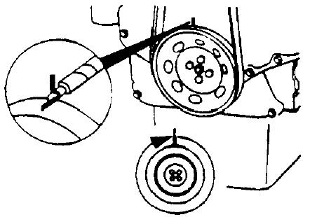
2. Locate Top Dead Centre (TDC) for Cylinder Number 1 by rotating the crankshaft slowly while pressing on the engine timing pin
3. When the pin engages the hole in the camshaft gear, Cylinder
Number 1 is at TDC on the compression stroke.

1 Camshaft gear
2 Engine timing pin
3 Gear housing
CAUTION
Be sure to disengage the pin after locating TDC.
Valve clearance intake: 0-254 mm exhaust: 0-508 mm
Check/set valves with engine cold - below 60°C
NOTE:
The clearance is correct when some resitance is ‘felt’ when the feeler gauge is slipped between the valve stem and the rocker lever.
With the engine in TDC position, check and adjust the following valve clearances.
Intake (I) cylinders: 1,2 Exhaust (E) cylinders: 1,3


Tighten the lock nut to 24 N.m and re-check the valve lash
Mark the pulley and rotate the crankshaft 360° degrees. Be sure timing pin is sisengaged, before rotating. The timing pin will not engage in this position. With the engine in this position, check and adjust the following valve clearances.
Intake (I) cylinders: 3,4 Exhaust (E) cylinders: 2,4
Tighten the lock nut to 24 N.m and re-check the valve lash. Install the valve covers and tighten capscrews to 24 N.m
CHECK FAN BELT TENSIONER BEARING BELT AND FAN HUB
Check the tensioner bearing With the fan belt removed rotate fan hub. The tensioner pulley should spin freely with no rough spots defected under hand pressure.
Check the tensioner bearing.
Replace bearing if damaged.
Check fan hub. With the drive belt removed, rotate fan hub.
NOTE:
The fan hub should spin freely without excessive end play.
Check the fan hub bearing.
Replace bearing if damaged.
CHECK FAN BELT TENSION
Measure the belt deflection at the longest span of the belt.
Maximum deflection: 9.5-12,7 mm If tension is low (deflection is outside range): (see “Check fan belt tensioner bearing, belt and fan hub.”)
Check belt & replace if damaged.
Check tensioner & replace if damaged.

EVERY 2000 HOURS SERVICE
Maintenance for every 100, 250, 500 and 1000 hours should be carried out at the same time.
CLEAN HYDRAULIC TANK STRAINER
WARNING
The oil is at high temperature immediately after the machine has been operated. Wait for the oil to cool down before changing the oil. When removing the oil filler cap, turn it slowly to release the internal pressure, then remove it carefully.
Prepare the following
Container to catch drained oil: min. 117 l capacity
Refill, capacity: 117 l
Prepare a handle for the socket wrench set.
1. Loosen 4 bolts, then remove cover (1).
When doing this, the cover may fly out under the force of spring (2), so push the cover down when removing the bolts.
2. Pull up the top of rod (3), and remove spring and strainer (4).
3. Remove the dirt stuck to strainer (4), then wash it in clean diesel oil or flushing oil. If strainer (4) is damaged, replace it with a new one.
4. Refit strainer (4) by inserting it into tank projecting part (5).
5. Install cover (1) with bolts.
CLEAN, CHECK TURBOCHARGER
Contact your Komatsu distributor for cleaning or inspection.
CHECK ALTERNATOR, STARTING MOTOR
The brush may be worn, or the bearing may have run out of grease, so contact your Komatsu distributor for inspection or repair. If the engine is started frequently, carry out inspection every 1000 hours.
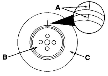
CHECK VIBRATION DAMPER
Check the index lines (A) on the damper hub (B) and the inertia member (C). If the lines are more than 1.59 mm out of alignment, replace the damper.
CHANGE OIL IN AXLES
1. Remove plugs (1) and (2) to drain oil.
2. Replace plug (2).
3. Attach tube and funnel to plug (1) hole and add oil until oil emerges when tube is removed.
4. Replace plug (1). Vibration damper
CHANGE OIL IN HUBS
1. Position hub with plug (1) at bottom and remove plug (1).
2. When all oil has drained out, rotate hub until plug hole is at the top.
3. Add oil (2.5 l each hub, front axle, 2.7 l each hub, rear axle) and rotate hub until filling hole is horizontal.
4. If oil emerges, allow excess to drain off and replace plug.
5. If no oil emerges, rotate hub until plug hole is at the top and add oil.
6. Rotate until hole is horizontal.
7. Repeat steps 4,5 + 6.
8. Replace plug.
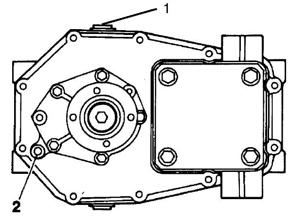
CHANGE OIL IN TRANSMISSION ASSEMBLY
TRANSMISSION
1. Remove plugs (1), (2) + (3) and allow oil to drain out.
2. Replace plug (3).
3. Add oil (approx. 1 l) until oil emerges from plug (2) hole.
4. Replace plugs (1) + (2).
CLUTCH
1. Remove plugs (4), (5) & (6) and allow oil to drain out.
2. Replace plugs (5) & (6).
3. Add oil (measure 0.5 l)
4. Replace plug (4).
CHANGE ANTIFREEZE
Follow the procedure of “CLEAN INSIDE OF COOLING SYSTEM” on page 194 for draining and refilling the cooling system.
CHECK AND ADJUST VALVE CLEARANCE
See section “CHECK & ADJUST VALVE CLEARANCE” on page 225 for procedure.
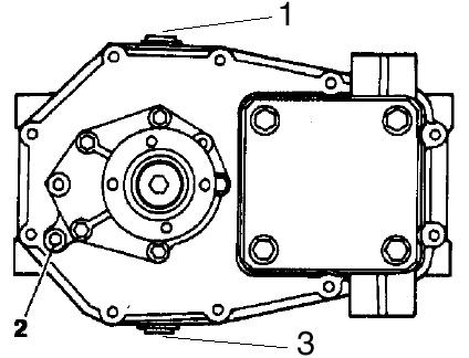
Drain ports
Fill port
EVERY 4000 HOURS SERVICE
Maintenance for every 100, 250, 500, 1000 and 2000 hours should be carried out at the same time.
CHECK WATER PUMP
Check that there is oil leakage, water leakage, or clogging of the drain hole. If any abnormality is found, contact your Komatsu distributor for disassembly and repair or replacement.
EVERY 5000 HOURS SERVICE
Maintenance for every 100, 250, 500 and 1000 hours should be carried out at the same time.
CHANGE OIL IN HYDRAULIC TANK
WARNING
The oil is at high temperature immediately after the machine has been operated. Wait for the oil to cool down before changing the oil. When removing the oil filler cap, turn it slowly to release the internal pressure, then remove it carefully.
Prepare the following
Container to catch drained oil: min. 117 l capacity
Refill, capacity: 117 l
Prepare a handle for the socket wrench set.
1. Swing the upper structure so that the drain plug under the hydraulic tank overhangs the undercarriage.

2. Retract the arm and bucket cylinders to the stroke end, then lower the boom and put the bucket teeth in contact with the ground.
3. Lock the control lever pad safety lock lever and stop the engine.
4. Remove the cover over the hydraulic tank and remove the cap of oil filler (F).
5. Set the oil container under the drain plug under the machine.
Using the handle, remove drain plug (P) and drain the oil.
Check the O-ring installed to plug (P), and if it is.damaged, replace the O-ring. After draining the oil, tighten drain plug (P). Tightening torque: 69 ± 10 Nm (7 ± 1 kgm).
When removing drain plug (P), be careful not to get oil on yourself.
6. Add the specified amount of engine oil through oil filler port (F) Check that the oil level is between H and L on the sight gauge.
For type of oil to be used, see “USE FUEL, COOLANT AND LUBRICANTS ACCORDING TO AMBIENT TEMPERATURE” on page 177.
NOTICE
When the hydraulic breaker is installed, the hydraulic oil deteriorates earlier than in normal bucket digging work. Therefore replace the hydraulic oil according to the table at the right.
7. After replacing hydraulic oil or replacing filter element and strainer, bleed air from the circuit according to the following procedure. Replacement interval (H)
Replacement interval for hydraulic oil
(When not Breaker operation (ratio %) Hydraulic Filler element using breaker) AD31373D (When using breaker only
Procedure for bleeding air
Follow steps 1 to 7 to bleed the air.
1. Bleeding air from pump
1. Loosen air bleeder (1) installed to the drain port, and check that oil oozes out. (Completion of air bleeding)
2. After completing the air bleeding operation, tighten the air bleeder.
NOTE:
If the pump is operated without filling the pump case with hydraulic oil, abnormal heat will be generated and this may lead to premature damage of the pump.
2. Starting engine
Start the engine according to “STARTING ENGINE” on page 113 keep running the engine at low idling for 10 minutes, and carry out the following procedure.
3. Bleeding air from cylinders
1. Run the engine at low idling, and extend and retract each cylinder 4 - 5 times without operating it to the end of its stroke. (Stop approx. 100 mm before the end of the stroke)
2. Next, operate each cylinder to the end of its stroke 3 - 4 times.
3. After this, operate each cylinder 4 - 5 times to the end of its stroke to completely bleed the air.
NOTICE
If, at first, the engine is run at high speed or the cylinder is operated to the end of its stroke, the air inside the cylinder may cause damage to the piston packing or other parts.
4. Bleeding air from swing motor (only after draining oil from swing motor case)
1. Run the engine at low idling, loosen air bleeding plug (1), and check that oil oozes out from air bleeding plug (1).
NOTICE
When doing this, do not operate the swing·
2. If oil does not ooze out, stop the engine, remove air bleeding plug (1), fill the motor case with hydraulic oil. 3. After completion of the air bleed operation, tighten air bleeding plug (1). 4. Run the engine at low idling, and swing 2 or more times slowly and uniformly to the left and right.
NOTICE
If the air is not bled from the swing motor, the bearings of the motor may be damaged.