9 minute read
TO OUR CUSTOMER

Thank you very much for purchasing an ISEKI tractor.
This operator's manual provides the information necessary for the operation of ISEKI TG tractor which has the HST assist system. Please refer to the operation's manual of standard HST models for ordinary operating and maintenance instructions of tractor. The contents are mainly composed of the following item:
Technical instructions : Essential Items which you should observe while operating the tractor
Before starting to operate the machine for the first time, you should read this operation manual and standard HST model's manual thoroughly and carefully until you are sufficiently familiar with the operation of the machine to do jobs safely and properly. The manual should be kept in a handy place so you can refer to it when required. You are advised to refer to it from time to time to refresh your understanding of the machine.
Your dealer has performed the pre-delivery service on your new machine. He will discuss with you the operating and maintenance instructions given in this manual, and instruct you in the proper and varied applications of this machine. Call on him at any time when you have a question, or need equipment related to the use of your machine.
Paragraphs in the manual and labels on the machine which are accompanied by a caution particularly important information about safe operation to avoid accidents. You should always keep precautions in mind and follow them during operation.
Be sure to wear personnel protective equipment during operation
In some of the illustrations used in this operation manual, panels or guards may have been removed for clarity. Never operate the tractor with these panels and guards removed. If the removal of a shield is necessary to make a repair, it must be replaced before operation.
All information, illustrations, and specifications contained in this manual are based on the latest information available at the time of publication. The right is reserved to make changes at any time without notice.
INSTRUMENTS & CONTROLS - HST TYPE -
CAUTION: Become familiar with all operating controls prior to operating Tractor. Read this book in its entirety before starting.
Instrument Panel
FIG. 1-2: Arrangement of gauges. Control switches and indicators located in instrument panel. Items are detailed in the descriptions that follow:
Electric Fuel Shut-Off
Turn the main switch to off position so as to stop engine.
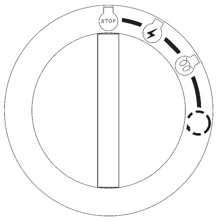
Main Switch
FIG. 1-3: Main switch, 1, has the four following positions:
・p OFF - Tractor engine and all electrical circuits off. (except for head light, turn/hazard position light, tail light, working lamp) Key can be removed.
・O ON - Power supplied to all circuits. Normal operating position. Linkage on fuel injection pump moves (electrically) to the run position.
・G GLOW - Energizes glow plugs to pre-heat combustion chambers and assist starting.
・f START - Starter activated. This position spring loaded to “ON”.
NOTE: Main switch must be turned to “ON” before any circuits will operate. PTO switch must be off and gear shift lever in neutral before engine can be started. This tractor is equipped with an electric fuel shut off. When main switch, 1, is turned to “start”, “on”, or “glow” position and gear shift lever is placed in neutral, a solenoid moves the fuel linkage on injection pump to run position to start engine. When main switch is turned to “off”, solenoid moves fuel linkage to off position to stop engine.
・When you heard the horn sound continuously on starting engine or operating Forward or Reverse pedal, please stop the engine.
・In the case of the horn sound a moment and stop on starting the engine, the machine is in a normal condition.
・When you heard the horn sound continuously on traveling, apply the brake and stop immediately. And cut off the engine.
FIG. 1-4: When main switch, 1, is selected to “GLOW” position, glow indicator, 2, will illuminate after several seconds to indicate the engine combustion chambers are preheated and allow cold engine to be started.
Indicator Light Strip
FIG. 1-5: Indicator light strip, 3, contains several warning lights to monitor certain functions. Currently used positions (from left to right) are:
・l Main (High) Beam - Illuminates when headlamps in front grille are selected to high beam position by light switch.
・M Power Take-Off (PTO) - Illuminates when PTO control switch is moved to engage PTO clutch pack (PTO operating). Light will go out when PTO switch is moved to off.
・o Engine Oil Pressure - Illuminates if engine oil pressure is low. If light comes on while engine is running, shut off engine immediately and investigate cause.
・b Battery Charge - Illuminates when main switch is turned “ON” and will go out after engine starts, to indicate battery is being charged.
・ Coolant Temperature - Illuminates when engine is overheating. Reduce engine speed to idle, allow to run at no load sevral minutes and investigate cause( refer to “Troubleshooting”).
・ Fuel - Illuminates when fuel is low level in the fuel tank.
・ Inspection - Illuminates when hourmeter indicates 50/100/200/300/400 ・・・ hour, please inspect your tractor.
・ Caution - Illuminates when it is not normal with starting engine or sensor of Power shift is not normal.
・ Parking Brake - Illuminates when parking brake lever is pulled up.
・ 4WD - Illuminates when 4WD is engaged by shifting 4WD lever.
・† Trailer Indicator - Blink when turn switch is ON with connecting 7 pins socket to your trailer or when hazard light switch is ON.
TG5390,5470
Coolant Temperature Gauge
FIG. 1-6: Gauge, 4, indicates engine coolant temperature when main switch is selected to ON
・ - Shows too cool temperature for severe work. Allow to warm before applying heavy load.
・ - Indicates overheating. Reduce engine speed to idle, allow to run at no load several minutes and investigate cause (refer to “Troubleshooting”).
CAUTION: Do not service hot engine. Allow to completely cool before servicing or removing radiator cap.
Tachometer
FIG.1-7 & 1-8: Scale,5, indicates engine speed in crank shaft revolutions per minute(rpm). Digital panel indicates not only engine revolutions but also traveling speed, rear PTO speed, mid PTO speed, hourmeter, trip meter.
Indication of digital panel is changed by pushing selectable switch,6.
When rear PTO speed is 540, engine revolutions is approximately 2430 rpm. Normally, the PTO speed should be between 540 and 600. Operating the PTO at a speed above 600 is too fast, and may result in breakdown of the tractor or implement.
Hourmeter is used to assist in maintenance intervals of tractor. The extreme right digit indicates 1 hour increments.
Tripmeter is used to assist in your operation. The extreme right digit indicates 1/10 hour increments.
Fuel Gauge
FIG. 1-9: Scale, 7, indicates level of diesel fuel in fuel tank when main switch is “ON”
NOTE: Use only clean diesel fuel and clean area to pre vent dirt/water entry into fuel tank when refilling.DO NOT run out of fuel as bleeding air from the system will be required. Keep fuel tank full to minimize condensation.
CAUTION: DO NOT refill fuel tank with engine running or hot. Allow cooling period. DO NOT smoke near fuel tank. Clean up any spilled fuel.
Horn / Light Turn Switch
FIG. 1-10: Horn / Light Turn Switch.
Horn Switch, 8 - Horn will sound when center switch button is depressed.
Light Switch, 9 - Is a rotary switch with three operating positions:
・OFF - Fully counterclockwise. All lights off.
・1st - Low beam headlamps and rear tail lights.
・2nd - Main (high) beam headlamps and rear tail lights.
NOTE: When high beam is selected (2nd position), light in indicator light strip will come on.
Turn Switch, 10 - Operate switch handle in direction Tractor is being turned. The appropriate flashing amber warning light (ROPS-mounted) will operate as turn signal. Return switch to center position to cancel.
NOTE: Turn lights will not self-cancel. Select turn/hazard light switch to center position after completing turn.
FIG. 1-11: Turn the position lamp switch, 11, to turn the position lamps on.
Hazard Light Switch, - Press switch, 12, to turn on hazard lights. Both flashing amber warning lights will operate at the same time.
CAUTION: Hazard lights must be used any time Tractor is driven on public roadway. Consult local agencies for other marking requirements.
TG5390,5470
FIG. 1-12: Turn/hazard indicator lights, 13 and 14, will operate with ROPS-mounted warning lights. This provides operator with easy indication of warning light selection.
Brakes
Brake Pedals & Parking Brakes
FIG. 1-13: Inner brake pedal, 1, and outer brake pedal, 2, independently control the respective left and right wheel brakes, to assist in turning.
During Tractor transport or high speed operation, brake pedals must be latched together using interlocking plate, 3.
CAUTION: Do not use individual wheel brakes for transporting or operating at high speed. Always latch pedals together using interlocking, plate, 3. Make sure brakes are adjusted evenly.
Parking Brake lever
WARNING: ALWAYS apply the parking brake before dismounting from the tractor.
FIG. 1-14 & 1-15: The parking brake acts on the tractor rear wheels. To engage the brake, pull upward on the parking brake lever, 4 to lock brakes in applied position. To release the parking brake, press the button on the end of the lever and push the lever down.
When pulling upward on the parking brake lever, the parking brake indicator light will illuminate.
Ensure the parking brake is fully released before driving off.
Engine Speed Controls
CAUTION: Always select engine speed to ensure safe operation. Reduce speed prior to turning or reversing Tractor.
IMPORTANT: DO NOT “race” or excessively load cold engine.
FIG. 1-16: Hand Throttle Lever, 1 - Controls engine speed and will remain in position selected by the operator. With hand lever forward, engine will idle. Engine speed increases as lever is pulled progressively backward.
TRANSMISSION SHIFT LEVER AND CONTROLS (HST type)
One shift lever is used to select a range of ground travel speed through different gear reductions within the drive train. A hydrostatic control unit (using a control pedal) allows infinitely variable speeds, from zero to top speed, in each range.
FIG. 1-17: Range Shift Lever, 1. Located to the left of the operator’s seat, range lever provides three major speed changes.
IMPORTANT: Tractor must be completely stopped when shifting.
Hydrostatic Control Pedal, 2. Located on the right side of the platform and it actuates the hydrostatic unit in forward or reverse travel direction.
Depressing the forward portion of the pedal moves Tractor forward, depressing the backward portion of the pedal moves Tractor reverse. As each movement is progressively depressed, a corresponding increase in ground speed of Tractor will be noticed in the appropriate direction.
Returning pedal towards spring-loaded neutral position, will slow Tractor and stop it when neutral position is reached. When pedal is completely released, Tractor should remain stopped with the pedal assembly in neutral position.
CAUTION: When you heard the horn sound continuously on traveling, apply the brake and stop immediately and cut off the engine.
Cruise Control Lever, 3. Located on the left side the steering wheel. This lever actuates hydrostatic control unit for forward travel only. Move forward pedal down until desired forward speed is achieved, then move cruise control lever backward to hold this speed. Move lever forward to slow down and stop.To release cruise control lever, move lever forward or depress brake pedals latched together with interlock plate.
WARNING: Cruise control should only be used in open spaces, without obstacles, with unobstructed view or traveling on load. Before using cruise control lever, be make sure to set brake pedals to be latched together with interlocking plate. If one brake is depressed to release cruise control, cruise control would not be released.
You should be thoroughly familiar with releasing cruise control. See operation section.
NOTE: Do not move cruise control lever without first moving the Hydrostatic control pedal downward in the forward position, to prevent mechanical failures. Do not use cruise control lever in reverse direction.
Differential Lock Pedal
FIG. 1-20: When differential lock pedal, 1, is depressed, both rear axles are locked together to provide equal traction to both rear wheels. This is especially important when operating in loose soil or slippery conditions.
Disengage differential lock, by releasing foot pedal. If lock does not immediately disengage, tap right and left brake pedals alternatively until pedal is released.
CAUTION: When differential lock is engaged, steering ability of Tractor will be greatly reduced. Disengage before attempting a turn. Do not use during transport.
FOUR-WHEEL DRIVE SHIFT LEVER
FIG. 1-21: Shift lever, 1, engages and disengages drive for the front axle. Lever forward, the front axle (4-WD) is disengaged. Lever backward, the front axle is engaged, and power is available to both front and rear axle. When shift lever is pulled backward, the 4-WD indicator light will illuminate.
IMPORTANT: Make sure the tractor is completely stopped before engaging or disengaging four-wheel drive.
Do not use 4-WD on hard surface. Rapid wear of front tires and possible drive line damage could occur if 4-WD is operated for prolonged periods on hard surface.