2 minute read
The contact pattern between the gears was wrong which was made during dis- assembly.


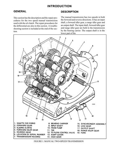
of the forward gear. The forward gear locks to the input shaft. Now the forward gear must turn with the input shaft. Power from the forward gear transfers to the forward idler gear then to the range idler gear. Then the power transfers to the range gear which is selected.
The selection of the range gear is similar to the selection of the direction gears. When the range gear is selected, the fork moves the sliding gear toward the selected gear. The selected gear now must turn with the output shaft. Power transfers from the range idler gear to the selected range gear which turns the pinion. If the range gears were in neutral, they would both turn freely on the output shaft.
Figure 2 shows the transfer of power through the gears of the transmission for two different conditions. The illustration at the top of Figure 2 shows the condition when the control levers are
REPAIRS
REMOVAL
Before removal of the transmission, check the contact pattern of the ring and pinion gear as described in Steps A - D. The results you get will be used for reference during assembly of the transmission.
A. Drain the oil from the drive axle.
B. Remove the upright assembly as described in THE UPRIGHT section.
C. Remove the cover from the differential assembly.
D. Apply grease to approximately 5 of the teeth on the ring gear as shown in Figure 9. Turn the pinion and check the pattern of contact on the ring gear. Compare the patterns you get with the patterns shown in Figure 10. If the pattern is correct, the shims for the output shaft will not have to be changed. moved to the REVERSE and HIGH positions. The clutch is engaged and power from the engine transfers to the input shaft. The direction control lever moves to REVERSE which locks the reverse gear to the input shaft. The reverse gear does not touch the forward idler gear the reverse gear turns the range idler gear. The range control lever moves to HIGH which locks the high gear to the output shaft. The range idler gear then turns the high gear and the output shaft.
The illustration at the bottom of Figure 2 shows the condition when the control levers are moved to FORWARD and LOW. The direction control lever moves to FORWARD which locks the forward gear to the input shaft. The forward gear turns the forward idler gear which turns the range idler gear. The range control lever moves to LOW which locks the low gear to the output shaft. The range idler gear then turns the low gear and the output shaft.
for the correct procedures.
A. When the engine and transmission are on the floor, fasten a lifting device to the transmission.
B. When the transmission has support, loosen the placebolts that hold the transmission to the flywheel housing. Make sure the input shaft does not bend the clutch disc during separation.
INSTALLATION
A. Use a lifting device to install the transmission to the flywheel housing. Use a new gasket during installation. The input shaft must align with the splines of the clutch disc. Make sure the input shaft does not bend the clutch disc.
B. Install the capscrews that hold the transmission to the flywheel housing. Tighten the capscrews to a torque of 35 1bf ft (47 N.m).