10 minute read
GASKET

Removal and Disassembly (See Figure 7)
A. If the hypoid ring and pinion are not to be replaced, check the contact pattern before disassembly. The pattern and gear clearance are used as references for assembly. See the ASSEMBLY section for the procedures.
B. Loosen the nut for the output gear.
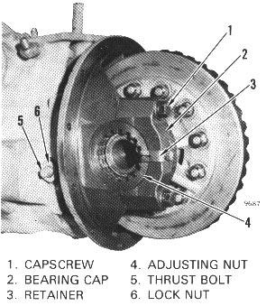
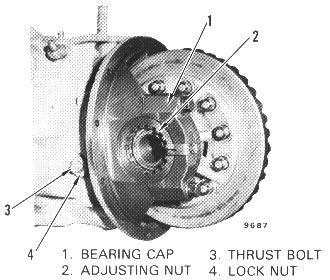
C. Loosen the thrust bolt for the ring gear. Remove the bearing caps, adjusting nuts and the ring gear assembly.
D. Remove the case for the ring gear and differential from the transmission housing.
E. Remove the nut for the output gear. Remove the output gear then pull the pinion from the transmission housing. G. If necessary, remove the ring gear from the case half. Remove the bolts from the case halves, then remove the spider and side gears.
Inspection
A. Check the hypoid and ring gear for wear. Inspect the differential pinions and axle gears for worn teeth. Inspect the spider for wear where the gears turn. There must not be any clearance between the spider and the holes for the spider in the differential case.
B. Check all bearings for damage. Replace the bearing cups and cones if there is any damage.
Assembly And Installation - H40-60XL (See Figure 8)
NOTE The ring and pinion gear must be replaced as a set.
9641
1. OUTPUT GEAR 2. SEALS 3. O-RING 4. BEARING CONE 5. BEARING CUP 6. SPECIAL SPACER 7. TRANSMISSION HOUSING 8. SHIMS 9. PINION 10. CAPSCREW 11. CASE 12. THRUST WASHER 13. AXLE GEAR 14. THRUST WASHER 15. PINION GEAR 16. SPIDER 17. BOLT 18. RING GEAR 19. CASE 20. WASHER 21. NUT 22. ADJUSTMENT NUT 23. BEARING CAP 24. CASE FOR RING GEAR 25. PILOT BEARING 26. SNAP RING
STEP 1. Lubricate and install an axle gear and thrust washer in the case. Put the differential pinion gears and thrust washers on the spider. Put the spider assembly into the case. Install the other side gear and the thrust washer. Put the two parts of the differential case together and install the capscrews. Tighten the bolts to 81 to 95 N.m(60 to 70 lbf ft). If the ring gear was removed from the differential case, put the ring gear in water that is 70°-80°C (160180°F). After 10 minutes, remove the ring gear from the water and put it on the differential case. Do not use a press or a hammer to install the ring gear. Apply Loctite® 277 and install the bolts, lock-washers, and nuts. Tighten the bolts 110-135 N.m (80-100 Ibf ft). Install the bearing cones on the case.
9641
1. CAPSCREW 2. CASE 3. THRUST WASHER 4. AXLE GEAR 5. THRUST WASHER 6. PINION GEAR 7. SPIDER 8. BOLT 9. RING GEAR 10. WASHER 11. NUT 12. BEARING CONE
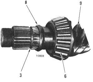
STEP 2. Install the bearing cups for the pinion in the housing. The two bearings are not the same size. Install the bearing cone for the pinion. Install the case for the ring gear. Install three of the capscrews and tighten them. Put a straight edge across the mount for the bearing caps. Measure the distance to the end of the bearing cone.
10065
1. BEARING CUPS 2. BEARING CONE 3. TRANSMISSION HOUSING 4. SHIMS 5. CASE FOR RING GEAR 6. STRAIGHT EDGE STEP 3. There is a dimension on the end of the pinion. After installation of shims on the bearing cone, the measurement in Step 2 must be equal to the pinion dimension ± 0.038 mm (0.0015 in.) Make sure you do not include the thickness of the straight edge in the measurement. Add or remove shims as necessary.
9698
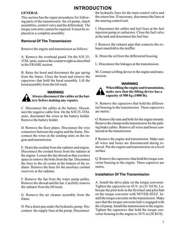
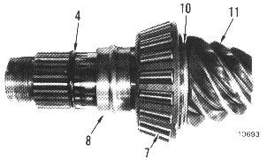
1. NUT 2. OUTPUT GEAR 3. O-RING *4. SEALS 5. BEARING CUPS 6. BEARING CONES
7. SHIMS 8. SPACER 9. PINION 10. PILOT BEARINGS 11. SNAP RING *LATER UNITS HAVE ONE SEAL STEP 4. Install the shims on the pinion. Install the bearing on the pinion. Install the pinion in the transmission housing, then install the special spacer and bearing cone. Install the seals in the housing. Install the Oring and the output gear. Install the washer and the nut. Do not install the case for the ring gear.
STEP 5. Tighten the nut to approximately 340 N.m (250 Ibf ft). Check the rotating torque of the pinion. The rotating torque must be 1.7 to 2.3 N.m (15 to 20 Ibf in). If the rotating torque is less than specifications, tighten the nut on the pinion. If the rotating torque is more than specifications, remove the pinion and install a new special washer. Tighten the nut on the pinion until the specified rotating torque is reached.
NOTE: 339 N.m (250 Ibf ft) of torque is needed to start to bend the special washer. Only 108-122 N.m (80-90 Ibf ft) of torque is needed to continue tightening the nut once the washer starts to bend.
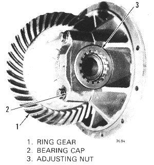
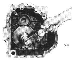
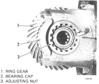
STEP 6. Install the ring gear, bearing cups and adjusting nuts in the case for the ring gear. Turn the adjusting nuts until they are approximately even with the bearing caps. Tighten the bolts for the bearing caps. STEP 7. Check the rotating torque of the ring gear. The rotating torque must be 2.3 to 2.8 N.m (20 to 25 lbf in). Loosen or tighten the adjusting nuts to get the rotating torque within specifications. Make a note of the number of threads from the edge of each bearing cap to each adjusting nut.
STEP 8. Install the pilot bearing. Apply sealant Hyster Part No. 264159 on the flange of the transmission housing and install the case for the ring gear. Tighten the capscrews to 57 to 68 N.m (42 to 50 lbf ft). Install the ring gear in the same position as determined in STEP 7.
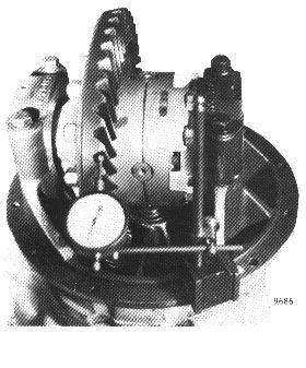
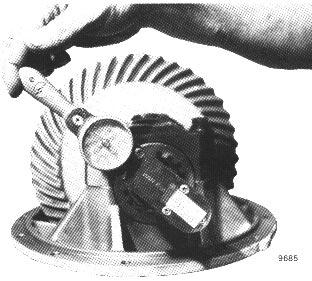
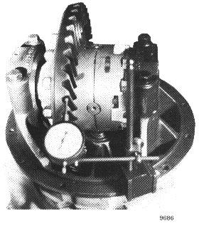
STEP 9. Check the clearance between the ring gear and pinion. Correct clearance is .20 to .28 mm (.008 to .011 inches). Move the adjusting nuts equal amounts to move the ring gear away from or closer to the pinion. Check that the clearance between the ring gear and pinion is correct.
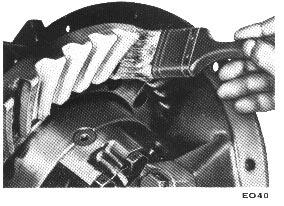
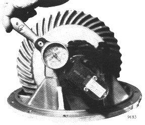
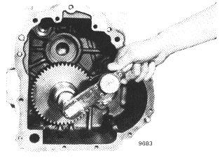
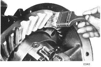
STEP 10. Check the pattern on the teeth of the ring gear by applying grease to the teeth. Put a prybar between the ring gear and the housing to keep the ring gear from turning freely. Turn the pinion shaft. Compare the pattern on the ring gear teeth with the patterns shown in Figure 9. Adjust gears as necessary.
STEP 11. Tighten the capscrews for the bearing caps to 224 to 251 N.m (165 to 185 Ibf ft). Install the retainers for the adjusting nuts.
STEP 12. Tighten the thrust bolt until it touches the ring gear. Loosen the bolt until there is .25 - .38 mm (0.010 - 0.015 in) clearance between the bolt and the ring gear. Tighten the lock nut.
FIGURE 8. ASSEMBLY AND INSTALLATION OF DIFFERENTIAL (Sheet 4 of 4)
TOOTH CONTACT IS NOT CORRECT
PINION IS TOO FAR FROM CENTER OF RING GEAR PINION IS TOO CLOSE TO CENTER OF RING GEAR
FIGURE 9. CONTACT PATTERNS
Assembly And Installation - S/H 2535XL (See Figure 10)
STEP 1. Lubricate and install an axle gear and thrust washer in the case. Put the differential pinion gears and thrust washers on the spider. Put the spider assembly into the case. Install the other side gear and the thrust washer. Put the two parts of the differential case together and install the capscrews. Make sure the identification marks are aligned. Tighten the capscrews to 47 to 61 N.m (35 to 45 lbf ft). If the ring gear was removed from the differential case, put the ring gear in water that is 70° to 80°C (160° to 180°F). After 10 minutes, remove the ring gear from the water and put it on the differential case. do not use a press or a hammer to install the ring gear. Tighten the cpscrews to 100 to 115 N.m (75 to 85 Ibf ft). Install the bearing cones on the case.
NOTE The ring and pinion gear must be replaced as a set.
1. CAPSCREW 2. CASE 3. THRUST WASHER 4. AXLE GEAR 5. THRUST WASHER 6. PINION GEAR 7. SPIDER 8. BOLT 9. RING GEAR 10. BEARING CONE
1. BEARING CUPS 2. SPACER 3. BEARING CONE 4. TRANSMISSION HOUSING 5. SHIMS 6. CASE FOR RING GEAR 7. STRAIGHT EDGE STEP 2. Install the bearing cups for the pinion in the housing. The two bearings are not the same size. Install the bearing cone for the pinion. Install the case for the ring gear. Install three of the capscrews and tighten them. Put a straight edge across the mount for the bearing caps. Measure the distance to the end of the bearing cone.
STEP 3. There is a dimension on the end of the pinion. After installation of shims on the bearing cone, the measurement in Step 2 must be equal to the pinion dimension ± 0.038 mm (0.0015 in). Make sure you do not include the thickness of the straight edge in the measurement. Add or remove shims as necessary.
STEP 4. Install the shims on the pinion. Install the bearing cone on the pinion. Install the pinion in the transmission housing, then install the special spacer and bearing cone. Install the seal in the housing. Install the O-ring and the output gear. Install the washer and the nut. Do not install the case for the ring gear.
1. NUT 7. BEARING CONES 2. WASHER 8. SPECIAL SPACER 3. OUTPUT GEAR *9. SPACER 4. O-RING 10. SHIMS 5. SEAL 11. PINION 6. BEARING CUPS *LATER UNITS DO NOT USE SPACER
STEP 5. Tighten the nut to approximately 340 N.m (250 Ibf ft). Check the rotating torque of the pinion. The rotating torque must be 1.7 to 2.3 N.m (15 to 20 Ibf in). If the rotating torque is less than specifications, tighten the nut on the pinion. If the rotating torque is more than specifications, remove the pinion and install a new special spacer. Tighten the nut on the pinion until the specified rotating torque is reached.
STEP 6. Install the ring gear, bearing cups and adjusting nuts in the case for the ring gear. Turn the adjusting nuts until they are approximately in the center of the bearing caps. Tighten the bolts for the bearing caps.
STEP 7. Check the rotating torque of the ring gear. The rotating torque must be 1.7 to 2.5 N.m (15 to 22 lbf in). Loosen or tighten the adjusting nuts to get the rotating torque within specifications. Make a note of the number of threads (or measure the distance) from the edge of each bearing cap to each adjusting nut. NOTE: See Note on Step 5, Page 14.
STEP 8. Apply sealant Hyster Part No. 264159 on the flange of the transmission housing and install the case for the ring gear. Tighten the capscrews to 57 to 68 N.m (42 to 50 lbf ft). Install the ring gear in the same position as determined in STEP 7.
STEP 9. Check the clearance between the ring gear and pinion. Correct clearance is 0.13 to 0.25 mm (0.005 to 0.010 inches). Move the adjusting nuts equal amounts to move the ring gear away from or closer to the pinion. Check that the clearance between the ring gear and pinion is correct.
STEP 10. Check the pattern on the teeth of the ring gear by applying grease to the teeth. Put a prybar between the ring gear and the housing to keep the ring gear from turning freely. Turn the pinion shaft. Compare the pattern on the ring gear teeth with the patterns shown in Figure 9. Adjust gears as necessary.
STEP 11. Tighten the capscrews for the bearing caps to 115 to 125 N.m (85 to 90 Ibf ft). Install the retainers for the adjusting nuts.
STEP 12. Tighten the thrust bolt until it touches the ring gear. Loosen the bolt until there is .25 -.38 mm (0.010 - 0.015 in) clearance between the bolt and the ring gear. Tighten the lock nut.