
2 minute read
W Series Hydraulic Gear Pump & Gear Motor


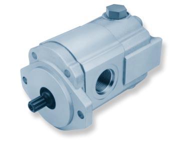
W Series Gear Pump
Retaining ring Shaft Seal Mounting Flange
Backup Ring
E-Seal
Single Pump (900 Series Shown)
Bearing block
O-Ring Dowel Pin
Gear Housing
Idler Gear Drive Gear
End Cover Spacer (as required) Bolt (metric)
(Note: Recent models use two long thru dowel pins)
Coupling Distance Plate
Double Pump (900 Series Shown)
Tools Required
• Metric Socket Set
• Internal Snap Ring Pliers
• Shaft Seal Sleeve
• Torque Wrench - 100 lb-ft capacity
Disassembly
Note: The following general instructions also apply to multiple section gear pumps, the only extra parts are the coupling between the drive shafts and the center distance plate which divides the two pump sections. This repair procedure also applies to the “W” series Gear Motors.
1. It is very important to work in a clean work area when repairing hydraulic products. Plug ports and wash exterior of pump with a proper cleaning solvent before continuing.
2. Remove port plugs and drain oil from pump.
W Series Gear Pump
6. Loosen the four metric hex head bolts.
7. Remove pump from vise and place on clean work bench, remove the four hex head bolts and spacers if applicable.
3. Use a permanent marker pen to mark a line across the mounting flange, gear housing and end cover. This will assure proper reassembly and rotation of pump.
4. Remove key from drive shaft if applicable.
11 remove the retaining ring with proper snap ring pliers.
12. Remove drive shaft from mounting flange. There is no need to protect the shaft seal as it will be replaced as a new item.
15. Remove the oil seal from mounting flange, be careful not to mar or scratch the seal bore.
16. Remove the dowel pins from the gear housing. Do not lose pins.
17. Remove seals from both bearing blocks and discard.
Inspect Parts For Wear
1. Clean and dry all parts thoroughly prior to inspection. It is not necessary to inspect the seals as they will be replaced as new items.
Check these points procedure will place the pressure port on the opposite side of the pump from its original position.
2. Check drive shaft spline for twisted or broken teeth, check keyed drive shaft for broken or chipped keyway. No marks or grooves on shaft in seal area, some discoloration of shaft is allowable.
3. Inspect both the drive gear shaft and idler gear shafts at the bearing points and seal area for rough surfaces and excessive wear.
Reassembly
(Note: New seals should be installed upon reassembly of pump or motor. Refer to page 8 for the necessary kit part numbers for the W-600,W-900 and W1500 pumps and motors.)
4. Inspect gear face for scoring or excessive wear. If the face edge of gear teeth are sharp, they will mill into the bearing blocks. If wear has occurred, the parts are unusable.
1. Install new shaft seal in mounting flange with part number side facing outboard. Press the seal into the seal bore until the seal reaches the bottom of the bore. Uniform pressure must be used to prevent misalignment or damage to the seal.
5. Inspect bearing blocks for excessive wear or scoring on the surfaces which are in contact with the gears. Also inspect the bearings for excessive wear or scoring.
6. Inspect the area inside the gear housing. It is normal for the surface inside the gear housing to show a clean “wipe” on the inside surface on the intake side. There should not be excessive wear or deep scratches and gouges.
General Information
It is important that the relationship of the mounting flange, bearing blocks and gear housing is correct. Failure to properly assemble this pump will result with little or no flow at rated pressure.
Reverse Shaft Rotation of Pump
(Note:This pump is not bi-rotational, if the shaft rotationmustbechangedthefollowingproceduremust be followed.) Reversing the shaft rotation of the “W” series gear pump may be accomplished by rotating, as a group, the two bearing blocks and the gear housing 180° in relationship to the remaining parts of the pump. This
2. Install retaining ring in groove in seal bore of mounting flange.
3. Place front and back bearing blocks on a clean surface with the E-seal grooves facing up. Apply a light coat-
