44 minute read
CONTROLS AND SAFETY EQUIPMENT


Become familiar with and know how to use all safety devices and controls on the skid-steer loader before operating it. Know how to stop loader operation before starting it. This Gehl loader is designed and intended to be used only with a Gehl attachment or a Gehl-approved referral attachment or accessory. Gehl cannot be responsible for operator safety if the loader is used with a non-approved attachment.
Guards and Shields
Whenever possible and without affecting loader operation, guards and shields are provided to protect against potentially hazardous areas. In many places, safety decals are also provided to warn of potential hazards and/or to display special operating procedures.
Read and thoroughly understand all safety decals on the loader before operating it. Do not operate the loader unless all factory-installed guards and shields are properly secured in place.
Operator Restraint Bar
Lower the restraint bar after entering the operator’s compartment. The restraint bar is securely anchored to the ROPS. The restraint bar switch and the seat switch form an interlock for the lift arm, tilt, drive and starter circuits (refer to the Safety Interlock System topic on page18 for more information).
WARNING WARNING WARNING
Never defeat the operator restraint bar or seat switch electrically or mechanically. Always wear the seatbelt.
Operator’s Seat
The seat is mounted on rails for rearward or forward repositioning. A spring-loaded latch handle activates the seat position adjustment mechanism.
Suspension seat (optional on all models): A weight adjustment knob is provided for individual operator adjustment.
1. Restraint Bar
2. Seatbelt
3. Seat Position Adjustment Lever
4. Suspension Seat Weight Adjustment Knob (optional)
Upper-Torso Restraint
Warning
Always wear the upper-torso restraint when operating in high speed.
The seatbelt should always be fastened during operation.
Important: Inspect the seatbelt(s) for damage before use, and replace if damaged. Keep seatbelt(s) clean. Use only soap and water to wash seatbelt(s). Cleaning solvents can cause damage to seatbelt(s).
Safety Interlock System
Hydraloc™
NEVER defeat the safety interlock system by mechanically or electrically bypassing any switches, relays or solenoid valves.
Warning
An interlock system is provided on the loader for operator safety. Together with solenoid valves, switches and relays, the interlock system:
Prevents the engine from starting unless the operator is sitting on the seat and the operator restraint bar is lowered.
Disables the lift arm, auxiliary hydraulics, attachment tilt and wheel drives whenever the operator leaves the seat, turns the keyswitch to Off or raises the restraint bar.
Testing the Safety Interlock System
Before exiting the machine, check the safety interlock system for proper operation:
Restraint Bar
With the engine running, raise the restraint bar. Test each of the controls. There should be no more than a slight movement of the lift arm, hitch and machine. If there is any significant movement, troubleshoot and correct the problem immediately. Contact your dealer if necessary.
Seat Switch
With the engine off and the restraint bar lowered, unfasten the seatbelt, and lift your weight off the seat. Try to start the engine. If the engine starts, turn off the engine, troubleshoot and correct the problem. Contact your dealer if necessary.
ROPS/FOPS
The ROPS/FOPS (Roll-Over/Falling Object Protective Structure) is designed to provide protection for the operator from falling objects and in case the loader tips or rolls over, provided the operator is secured inside the ROPS by the seatbelt and restraint bar.
Never operate the loader with the ROPS/FOPS removed or locked back.
Parking Brake
This skid-steer loader is equipped with a spring-applied, hydraulic-released parking brake. The parking brake engages when the operator lifts the restraint bar, exits the seat or shuts off the engine. The brake can also be applied manually by using the switch located on the left control panel of the ROPS/FOPS. A red indicator lights on the left control panel when the parking brake is applied.
Horn
Pressing the button on the lower right portion of the control handle sounds the horn (optional on all models).
Rear Window Emergency Exit
The ROPS/FOPS rear window has three functions: noise reduction, flying objects barrier and emergency exit.
To use the emergency exit, pull on the yellow warning tag at the top of the window and remove the seal. Push or kick out the window and exit.
See your local automotive glass specialist to reinstall the window.
Lift Arm Support Device
The lift arm support device is used as a cylinder lock to prevent the raised lift arm from lowering unexpectedly. Be sure to engage the support device when the lift arm is raised for service. When the support device is not being used, return it to its storage position. The support device is a safety device that must be kept in proper operating condition at all times. The following steps ensure correct usage:
Warning
The safest method of engaging the lift arm support device requires two people – one person inside the loader and another person outside the loader to engage the support device.
Important: With the keyswitch OFF and the solenoid valve functioning properly, the lift arm should stay raised if the lift control is moved to “lower”. If the solenoid valve does not hold the lift arm raised, lower the lift arm completely and contact your Gehl dealer immediately to determine why the cause.
Engagement
To engage the lift arm support device:
1.Lower the lift arm fully.
2.Stop the engine.
3.Leave the operator’s compartment. Press in and hold the lock pin button to release its locking mechanism. Remove the lock pin holding the support device up against the lift arm. Allow the support device to come down into contact with the lift cylinder.
4.Return to operator’s compartment and restart the engine.
5.Use the lift control to raise the lift arm until the support device drops over the end of the lift cylinder and around the cylinder rod. Slowly lower the lift arm until the free-end of the support device contacts the top end of the lift cylinder.
6.Look to make sure the support device is secure against the cylinder end. Then, stop the loader engine, remove the key and leave the operator’s compartment.
Disengagement
To return the lift arm support device to its storage position:
1.Start the engine;
2.Raise the lift arm fully;
3.Stop the engine;
4.Before leaving the operator’s compartment, check to make sure that the lift arm is being held in the raised position by the solenoid valve (See Note below).
Note: With the keyswitch OFF and the solenoid valve working, the arm will stay raised when the lift control is moved forward. If the valve does NOT hold the lift arm and it begins to lower, do NOT leave the operator’s compartment. Instead, have someone store the support device for you. Then, contact your Gehl dealer to determine the reason why the lift arm lowers while the keyswitch is in the OFF position.
5.To store the support device, raise it up until it contacts the lift arm. Press in and hold the lock pin button to release its locking mechanism. Insert the lock pin through the hole in left arm and through the support device.
Accessory Plug
The accessory plug is located at the bottom of the left instrument panel.
Dome Light
The dome light is located on the right side of the ROPS head liner. Push the dome light to turn on the light.
Work Lights
Loaders have two sets of work lights. The front work lights are located at the top of the ROPS/FOPS. The rear work lights are located at the rear of the engine cover.
Heater (optional)
Loaders with the optional heater have a dial on the left instrument panel to control the fan speed.
Heater and Air Conditioner (optional)
Loaders with the combination heater/ air conditioner have two controls on the left instrument panel: fan speed, air conditioner on/off, and temperature.
1. Fan Speed: Controls the rate at which air exits the vents.
2. Heater/Air Conditioner Selector Switch: Turns on either the heater or air conditioner. Center off position allows fan only operation for air circulation.
Note: The operator will feel cooler with only the two front vents opened and aimed at the upper body.
Engine Speed Control
A hand throttle lever (Figure6) is provided for adjusting the engine speed. Move the control forward to increase and rearward to decrease the engine speed.
T-Bar, Dual Hand and T-bar/Joystick Controls Only: A right-foot operated throttle pedal is provided to control the engine speed (Figure7). The pedal linkage is spring-loaded to return to the pre-set hand throttle setting.
Two-Speed Transmission (optional)
Loaders with the optional two-speed transmission have a button on the left control handle for shifting between High (H) and Low (L). Shifting to High allows the machine to exceed 8mph (13km/h), up to a maximum speed of 12.4mph (20km/h).
Hydraglide™ Ride Control System (optional)
Loaders with the optional ride control feature have a button on the right control handle for shifting between normal mode and ride control mode. The ride control system provides a smoother ride over uneven surfaces. Press the button once to activate the system and again to deactivate. The ride control system is automatically deactivated when the machine is shut off.
When hydraglide is activated, the lift arm may drop slightly without a load or several inches with a heavy load.
Auto-Shutdown System
The auto-shutdown system will activate if the loader has an over-temperature situation or no oil pressure for more than 30 seconds. An audible alarm will sound and the Engine Coolant Temperature light or Engine Oil Pressure light will turn on and the loader will shut down after approximately 30 seconds.
Attachment Mounting
The skid-steer loader is equipped with either the standard manual All-Tach hitch or the optional Power-A-Tach hitch for mounting a bucket and other attachments.
All-Tach™ Hitch
With the standard hitch mechanism, two latch levers secure the attachment. Rotate the levers until the handles are horizontal to engage the lock pins. Rotate the levers until the handles are vertical to disengage the lock pins. (Refer to page40 for more information.)
To prevent unexpected release of the attachment from the hitch, be sure to secure the latch pins by rotating the levers all the way to the stops.
Power-A-Tach™ Hitch
With the optional hitch mechanism, a switch on the left control panel activates the latch pins. Metal “flags” on the pins indicate their position: the pin flags rotate to a horizontal position when engaging the pins and a vertical position when disengaging the pins. (Refer to page40 for more information.)
To prevent unexpected release of the attachment from the hitch, be sure the latch pins are secure by verifying that the pin flags have moved fully to the outside of the hitch.
Warning
Instrument Panels
The instrument panels contain the switches and indicator lights. Symbols on the indicator lights are visible only when the indicator light are on.
Left Panel
1. Two-Speed Transmission (optional) –Lights when high speed is engaged.
2. Parking Brake – Lights when the parking brake is applied.
3. Power-A-Tach™ Hitch (optional) – Used to operate the Power-A-Tach hitch.
4. Fan (optional) – Used to control the fan for the air conditioner and heater.
5. Heater/Air Conditioner Selector – Used to manually control the heater and air conditioner.
6. Auxiliary Hydraulic Switch (Detent) (Hand/Foot Models only) – A three-position detented switch use for continuous operation.
7. Accessory Plug – 12-volt DC power outlet.
8. Hydraglide™ Ride Control System (optional) – Lights when the ride control system is activated.
9. Float Indicator (T-bar/Joystick control option only) – Lights when float function is activated.
10. Parking Brake Switch – Used to manually apply the parking brake.
Right Panel
1. Hourmeter – Displays the total operating hours of the loader.
2. Fuel Level Gauge – Displays the amount of fuel in the tank.
3. Engine Oil Temperature Gauge – Displays the temperature of the engine oil.
4. Engine Oil Temperature – Lights if the engine oil is too hot this warns the operator to stop the engine and determine and correct the cause for the high temperature. During normal operation this indicator should be OFF.
5. Hydraulic Oil Temperature – Lights if the hydraulic oil is too hot this warns the operator to reduce the hydraulic load and determine the cause of the high temperature. During normal operation this indicator should be OFF.
6. Light Switch – Controls all the lights on the loader. Symbols denote the four positions of the light switch. In a clockwise direction these are:
•Off
•Tail Lights
•Front Work Lights with Tail Lights
•both Front and Rear Work Lights
For the lights to function, the keyswitch must be in the RUN position.
7. Keyswitch – In a clockwise rotation, these positions are:
• OFF Position – With the key vertical, power from the battery is disconnected from the controls and instrument panel electrical circuits. This is the only position the key can be inserted or removed from the keyswitch.
• ON (or RUN) Position – With the key turned one position clockwise from vertical, power from the battery is supplied to all control and instrument panel circuits.
• START Position – With the key turned fully clockwise, the electric starter energizes, start the engine. Release the key to RUN position after the engine starts.
Note: The engine cannot be started unless the operator is sitting in the seat and the restraint bar is lowered.
8. Circuit Breakers – Four circuit breakers on the instrument panel protect the loader electrical circuits.
Important: Do not attempt to defeat the circuit protection by jumping across or by installing a higher amperage circuit breaker.
9. Fasten Seatbelt – A momentary visual (and audible) indicator to remind the operator to fasten the seatbelt(s).
10. Engine Oil Pressure – Lights if the engine oil pressure is too low. Warns the operator to immediately stop the engine and determine the cause for the low pressure. During normal operation this indicator should be OFF.
11. Battery – Lights if the charging voltage is too high or too low. During normal operation this indicator should be OFF.
12. Preheat Indicator Lamp – Lights when the preheat is active. During normal operation this indicator should be off.
T-Bar Controls
Your loader may be equipped with the Gehl T-Bar control option. The left T-Bar controls the drive and the right T-Bar controls the lift/tilt.
Drive Controls
Figure12 T-Bar Controls
1. Lift/Tilt Control
2. Drive Control
Forward, reverse, speed and turning maneuvers are accomplished by movement of the left T-Bar. To go forward, push the control forward; for reverse, pull the control rearward. To turn right, turn the control clockwise; to turn left, turn the control counterclockwise. For gradual turns, move the T-Bar slightly forward or rearward. For sharp turns, turn the control clockwise or counterclockwise.
Moving the T-Bar farther from neutral increases the speed steadily to the maximum travel speed. Tractive effort decreases as speed increases. To get maximum tractive effort, move the T-Bar only slightly away from the neutral position. The engine will stall if the control is moved too far forward when loading the bucket.
Be sure the T-Bar controls are in neutral before starting the engine. Operate the controls gradually and smoothly. Excessive speed and quick control movements without regard for conditions and circumstances are hazardous and could cause an accident.
Lift/Tilt Control
Moving the lift arm and tilting the attachment are accomplished by movement of the right T-Bar. To raise the lift arm, pull the control straight rearward; to lower the lift arm, push the control straight forward. To tilt the attachment forward and down, twist the control clockwise; to tilt the attachment up and back, twist the control counterclockwise.
Note: The speed of the lift/tilt motion is directly proportional to the amount of T-Bar movement and engine speed.
To place the lift arm into the detent (“float”) position, push the right T-Bar all the way forward. This position allows the lowered lift arm to float while traveling over changing ground conditions.
Never push the lift/tilt T-Bar control into the “float” position with the attachment loaded or raised, because this will cause the lift arm to lower very rapidly.
T-Bar/Joystick Controls
Your loader may be equipped with the Gehl T-Bar/Joystick control option. The left T-Bar controls the drive and the right joystick controls the lift/tilt.
Drive Controls
Forward, reverse, speed and turning maneuvers are accomplished by movement of the left T-Bar. To go forward, push the control forward; for reverse, pull the control rearward. To turn right, turn the control clockwise; to turn left, turn the control counterclockwise. For gradual turns, move the T-Bar forward or rearward and turn slightly. For sharp turns, turn the control clockwise or counterclockwise.
Moving the T-Bar farther from neutral increases the speed steadily to the maximum travel speed. Tractive effort decreases as speed increases. To get maximum tractive effort, move the T-Bar only slightly away from the neutral position. The engine will stall if the control is moved too far forward when loading the bucket.
Be sure the T-Bar controls are in neutral before starting the engine. Operate the controls gradually and smoothly. Excessive speed and quick control movements without regard for conditions and circumstances are hazardous and could cause an accident.
Lift/Tilt Control
Moving the lift arm and tilting the attachment are accomplished by movement of the right joystick. To raise the lift arm, pull the control straight rearward; to lower the lift arm, push the control straight forward. To tilt the attachment forward and down, move the control to the right; to tilt the attachment up and back, move the control to the left.
Note: The speed of the lift/tilt motion is directly proportional to the amount of joystick movement and engine speed.
To place the lift arm into the detent (“float”) position, push and hold the left button on the right joystick. This mode allows the lowered lift arm to move up and down without moving the T-bar while traveling over changing ground conditions. An indicator light in the left instrument panel will blink when float is activated.
Warning
Never push the float control button with the attachment loaded or raised, because this will cause the lift arm to lower very rapidly.
Releasing the float button will cancel the float mode if the button was pressed less than five seconds. If the float mode button is pressed longer than five seconds, the float feature will stay on and the float indicator lamp will light continuously until the button is pressed again.
Hand/Foot Controls
Your loader may be equipped with the hand/foot control option. The handles control the drive and the foot pedals control the lift/tilt.
Drive Controls
Forward, reverse, speed and turning maneuvers are accomplished by movement of the control handles. To go forward, push both handles forward; for reverse, pull both handles rearward. For turning, move one handle farther forward or rearward than the other handle. Turn direction is determined by which handle is moved farther forward; to turn left, move the right handle farther forward than the left handle; to turn right, move the left handle farther forward than the right handle. For sharp turns, move the handles in opposite directions.
Figure14 Hand/Foot Controls

Moving the handles farther from neutral increases the speed steadily to the maximum travel speed. Tractive effort decreases as speed increases. To get maximum tractive effort, move the handles only slightly away from the neutral positions. The engine will stall if the handles are moved too far forward when loading the bucket.
Be sure the controls are in neutral before starting the engine. Operate the controls gradually and smoothly. Excessive speed and quick control movements without regard for conditions and circumstances are hazardous and could cause an accident.
Lift/Tilt Controls
Moving the lift arm and tilting the attachment are accomplished by movement of the foot pedals. The left pedal raises and lowers the lift arm; the right pedal tilts the attachment. To raise the lift arm, push down on the back of the left pedal with your left heal; to lower the lift arm, push down on the front of the left pedal with the toes of your left foot. To tilt the attachment forward and down, push down on the front of the right pedal with the toes on your right foot; to tilt the attachment up and back, push down on the back of the right pedal with your right heel.
Note: The speed of the lift/tilt motion is directly proportional to the amount of pedal movement and engine speed.
To place the lift arm into the detent (“float”) position, use the toes of your left foot to push the front of the left pedal all the way down. This position allows the lowered lift arm to float while traveling over changing ground conditions.
Never push the left pedal into the “float” position with the attachment loaded or raised, because this will cause the lift arm to lower very rapidly.
Dual-Hand Controls
Your loader may be equipped with the dual-hand control option. The left handle controls the left side drive and the lift. The right handle controls the right side drive and the tilt.
Drive Controls
Forward, reverse, speed and turning maneuvers are accomplished by pushing and pulling the handles. To go forward, push both handles forward; for reverse, pull both handles rearward. For turning, move one handle farther forward or rearward than the other handle. Turn direction is determined by which handle is moved farther forward; to turn left, move the right handle farther forward than the left handle; to turn right, move the left handle farther forward than the right handle. For sharp turns, move the handles in opposite directions.
Moving the handles farther from neutral increases the speed steadily to the maximum travel speed. Tractive effort decreases as speed increases. To get maximum tractive effort, move the handles only slightly away from the neutral position. The engine will stall if the handles are moved too far forward when loading the bucket.
Be sure the controls are in neutral before starting the engine. Operate the controls gradually and smoothly. Excessive speed and quick control movements without regard for conditions and circumstances are hazardous and could cause an accident.
Lift/Tilt Controls
Moving the lift arm and tilting the attachment are accomplished by rotating the control handles. To raise the lift arm, rotate the left handle outward (to the left); to lower the lift arm, rotate the left handle inward (to the right). To tilt the attachment forward and down, rotate the right handle; to tilt the attachment up and back, rotate the right handle inward.
Note: The speed of the lift/tilt motion is directly proportional to the amount of control movement and engine speed.
To place the lift arm into the detent (“float”) position, push the left handle all the way inward. This position allows the lowered lift arm to float while traveling over changing ground conditions.
Never push the lift/tilt control into the “float” position with the attachment loaded or raised, because this will cause the lift arm to lower very rapidly.
Auxiliary Hydraulic Controls
Auxiliary hydraulics are used with attachments that have a mechanism requiring its own hydraulic power.
Important: Always be sure the auxiliary hydraulic control is in neutral before starting the loader or disconnecting the auxiliary hydraulic couplers.
Standard-Flow Auxiliary Hydraulic Control
Loaders are shipped from the factory with a standard-flow auxiliary hydraulic system with flat-face couplers. The couplers are located under the lift arm on the left hand side.
A second set of hydraulic couplers can be added to the front of the lift arm by ordering a field installation kit.
T-Bar and Dual-Hand Control Loaders: A foot pedal is used to control the direction of oil flow. A latch is provided to lock the foot pedal for continuous operation (Figure16).
Hand/Foot Control Loaders: The right handle controls the direction of oil flow. A locking pin locks it in the up position for continuous operation (Figure17).
High-Flow Auxiliary Hydraulic Control (optional)
In addition to a standard-flow auxiliary hydraulic system, some loaders are equipped with a reversible high-flow auxiliary hydraulic system. The couplers are located on the right lift arm. High-flow auxiliary hydraulics are used for operating certain hydraulic attachments (e.g., cold planer, snowblower) that require higher flows.
A 3-position control lever, located behind the right control handle, is used to control the direction of oil flow. The lever is spring-centered, with a detent in the forward position for continuous operation.
Warning
Before starting the engine and operating the loader, review and comply with all safety recommendations in the Safety chapter of this manual. Know how to stop the loader before starting it. Also, be sure to fasten and properly adjust the seatbelt(s) and lower the operator restraint bar.
Before Starting the Engine
Before starting the engine and running the loader, refer to the Controls and Safety Equipment chapter and familiarize yourself with the various operating controls, indicators and safety devices on the loader.
Starting the Engine
The following procedure is recommended for starting the engine:
1.Carefully step up onto the back of the bucket or attachment and grasp the handholds to get into the operator’s compartment.
2.Fasten the seatbelt(s) and lower the restraint bar.
3.Verify the following: the lift/tilt, drive and auxiliary hydraulic controls are in their neutral positions, the parking brake switch is on.
4.Push the throttle lever forward to approximately half speed.
Note: When the key is turned to the RUN position, an indicator will light on the instrument panel and a buzzer will sound momentarily to remind you to check that your seatbelt is fastened.
5.Turn the key to the start position.
Note: If temperature is below 32°F (0°C), see Cold-Starting Procedure, on page38.
Important: Do not engage the starter for longer than 15 seconds at a time. Longer use can overheat and damage the starter. If the engine fails to start within 15 seconds, return the key to the off position. Allow the starter to cool for 20seconds and repeat Step 5.
After the engine starts, allow a sufficient warm-up time before attempting to operate the controls.
Important: If the indicator warning lights do not go off, stop the engine and investigate the cause.
Cold-Starting
If the temperature is below 32°F (0°C), try the following to make starting the engine easier:
Replace the engine oil with SAE 10W30 oil; Make sure the battery is fully charged; Install an engine block heater. An oil pan heater is recommended for star ting in temperatures of 20°F (-7°C) or lower. See your dealer for heater options.
Let the engine run for a minimum of five minutes to warm the engine and hydraulic fluid before operating the loader.
Cold-Starting Procedure
Do not use starting fluid (ether) with preheat systems. An explosion can result, which can cause engine damage, injury or death.
1.Turn the key to the run position. If the preheat light on the right instrument panel comes on, wait until it goes out.
2.Turn the key switch to the start position.
3.Repeat if engine does not start.
Stopping the Loader
The following procedure is the recommended sequence for stopping the loader:
1.Check that the drive control handle(s) is (are) in neutral position;
2.Lower the lift arm and rest the attachment on the ground;
3.Pull the throttle lever back to the low idle position (and/or take your foot off the throttle pedal for hands-only control machines);
4.Turn the keyswitch to the off position and remove the key; and
5.Raise the restraint bar, unfasten the seatbelt(s) and grasp the handholds while climbing out of the operator’s compartment.
Note: The skid-steer loader is equipped with a spring-applied automatic parking brake. The parking brake is applied when the operator lifts the restraint bar, leaves the operator’s seat, shuts off the engine or actuates the parking brake switch.
Parking the Loader
Park the loader away from traffic on level ground. If this is not possible, park the loader across the incline and block the tires to prevent movement.
Jump-starting
If the battery becomes discharged or does not have enough power to start the engine, use jumper cables and the following procedure to jump-start the loader engine.
The ONLY safe method for jump-starting a discharged battery is for TWO PEOPLE to perform the following procedure. The second person removes the jumper cables so that the operator does not have to leave the operator’s compartment with the engine running. NEVER make jumper cable connections directly to the starter solenoid of either engine. DO NOT start the engine from any position other than on the operator’s seat and then ONLY after being sure ALL controls are in “neutral”.
Closely follow the procedure, in order, to avoid personal injury. In addition, wear safety glasses to protect your eyes and avoid leaning over the batteries while jump-starting.
DO NOT jump-start the battery if it is frozen, because it may rupture or explode.
Note: BE SURE the jumper battery is a 12 volt D.C. battery.
1.Turn the keyswitches of both vehicles to OFF, be sure the vehicles are in “neutral” and NOT touching each other.
2.Connect the positive (+) jumper cable to the positive (+) battery terminal on the disabled loader first. DO NOT allow the positive clamps to touch any metal other than the positive (+) battery terminals.
3.Connect the other end of the positive jumper cable to the jumper vehicle’s battery positive (+) terminal.
4.Connect the negative (-) jumper cable to the jumper vehicle’s battery negative (-) terminal.
5.Make the final negative (-) jumper cable connection to the disabled loader’s engine block or loader frame (ground) – NOT to the disabled battery’s negative post. If connected to the engine, keep the jumper clamp away from the battery, fuel lines and moving parts.
6.Start the loader. If it does not start at once, start the jumper vehicle engine to avoid excessive drain on the booster battery.
7.After the disabled loader is started and running smoothly, have the second person remove the jumper cables (negative (-) jumper cable first) from the jumper vehicle’s battery and then from the disabled loader while being sure NOT to short the two cables together.
Allow sufficient time for the skid-steer loader alternator to build-up a charge in the battery before attempting to operate the loader or shut the engine off.
Changing Attachments
To prevent unexpected release of the attachment from the hitch, be sure to properly secure the hitch latch pins by rotating the latch levers all the way (manual All-Tach™ hitch) or by ensuring that the pin flags are all the way to the outside (Power-A-Tach™ hitch).
The skid-steer loader features either a manual or a power hitch for mounting a bucket or other attachment conforming to SAE Standard J2513.
On a manual All-Tach hitch (Figure20), two latch levers engage the latch pins to secure the attachment. On a Power-A-Tach hitch (Figure21), a switch on the left control panel activates the latch pins to secure the attachment.

Connecting Attachments
1. Manual hitch: Rotate the latch levers until the handles are horizontal to engage the lock pins.
2. Power hitch: Activate the switch to unlock the hitch and fully retract the latch pins.
3.Start the loader engine. Be sure the lift arm is lowered and in contact with the loader frame.
4.Align the loader squarely with the back of the attachment.
5.Tilt the hitch forward until the top edge of the hitch is below the flange on the back side of the attachment and centered between the vertical plates.
6.Slowly drive the loader forward and, at the same time, tilt the hitch back to engage the flange on the back side of the attachment.
7.Stop forward travel when the flange is engaged, but continue to tilt the hitch back to lift the attachment off the ground.
8. Manual hitch: Exercise the MANDATORY SAFETY SHUTDOWN PROCEDURE (page6). Exit the operator’s compartment and rotate the latch levers to the horizontal position to fully engage the latch pins.
9. Power hitch: Activate the switch to lock the hitch and fully engage the latch pins.
Important: To check that the attachment is properly installed, apply downward pressure to the attachment prior to operating.
Connecting Auxiliary Hydraulic Couplings
Note: With the engine off, key in the on position and the restraint bar down, the auxiliary hydraulic control can be moved to relieve any pressure in the hydraulic system.
Standard-Flow Auxiliary Hydraulics
Coupler hookup is located on the left lift arm. When the auxiliary control is in the detent position, the top coupler is “pressure”, and the bottom coupler is “return”.
High-Flow Auxiliary Hydraulics
Coupler hookup is located on the right lift arm. When the auxiliary control is in the detent position, the top coupler is “pressure”, and the middle coupler is “return”. The smaller bottom coupler is for the case drain.
Warning
Only connect high-flow attachment couplers to the high-flow auxiliary couplers.
Removing Attachments
1.Tilt the hitch back until the attachment is off the ground.
2.Exercise the MANDATORY SAFETY SHUTDOWN PROCEDURE (page6).
3.Relieve any hydraulic pressure in the auxiliary and attachment lines.
a.Turn the key on (do not start the engine).
b.With the restraint bar down, move the auxiliary hydraulic control back and forth. This will relieve the pressure in the hydraulic system.
4.With the engine off, leave the operator’s compartment and disconnect the auxiliary hydraulic hoses.
5. Manual hitch: Rotate the hitch latch levers to the vertical position to fully retract the latch pins.
Power hitch: Turn the key ON (do not start the engine) and activate the switch to unlock the hitch and fully retract the latch pins.
6.Start the engine and be sure that the lift arm is fully lowered and in contact with the loader frame.
7.Tilt the hitch forward and slowly back the loader away until the attachment is free from the loader.
Self-Leveling
The feature is intended to automatically keep the attachment level while the lift arm is being raised.
Using a Bucket
Warning
Always maintain a safe distance from electric power lines and avoid contact with any electrically charged conductor or gas line. Accidental contact or rupture can result in electrocution or an explosion. Contact the “Digger’s Hotline” or proper local authorities for utility line locations before starting to dig.
Driving over Rough Terrain
When traveling over rough terrain, drive slowly with the bucket lowered.
Driving on an Incline
When traveling on an incline, travel with the heavy end pointing uphill.
Digging with a Bucket
Approach the digging site with the lift arm slightly raised and the bucket tilted forward until the edge contacts the ground. Dig into the ground by driving forward and gradually lowering the lift arm (Figure22).
When the bucket is filled, tilt the bucket back, and back the loader away from the material. Rest the lift arm against the loader frame before proceeding to the dumping area.
Always carry the loaded bucket with the lift arm resting on the loader frame. For additional stability when operating on inclines, always travel with the heavier end of the loader toward the top of the incline.
Warning
Loading a Bucket
Approach the pile with the lift arm fully lowered and the bucket tilted slightly forward until the edge contacts the ground. Drive forward, lifting the lift arm and tilting back the bucket to fill it. Back away from the pile (Figure23).
Dumping the Load Onto a Pile
Carry a loaded bucket as low as possible until the pile is reached. Gradually stop forward motion and raise the lift arm high enough so that the bucket clears the top of the pile. Then, slowly move the loader ahead to position the bucket to dump the material on top of the pile. Dump the material and then back the loader away while tilting the bucket back and lowering the lift arm.
Warning
Never push the controls into “float” position with the bucket or attachment loaded or raised, because this will cause the lift arm to lowering rapidly.
Dumping the Load Into a Box
Carry the loaded bucket low and approach the vehicle or bin. Stop your approach as close to the side of the box as possible while allowing for clearance to raise the lift arm and loaded bucket. Next, raise the lift arm until the bucket clears the top of the box and move the loader ahead to position the bucket over the inside of the box. Dump the material and then back away from the box while tilting the bucket back and lowering the lift arm (Figure24).
Dumping the Load Over an Embankment
Do not drive too close to an excavation or ditch. Be sure the surrounding ground has adequate strength to support the weight of the loader and the load. Carry the loaded bucket as low as possible while traveling to the dumping area. Stop the loader where the bucket extends half-way over the edge of the embankment. Tilt the bucket forward and raise the lift arm to dump the material. Dump the material and then back away from the embankment while tilting the bucket back and lowering the lift arm.
Warning
Scraping with a Bucket
For scraping, the loader should be operated in the forward direction. Position the lift arm down against the loader frame. Tilt the bucket cutting edge forward at a slight angle to the surface being scraped. While traveling slowly forward with the bucket in this position, material can flow over the cutting edge and collect inside the bucket (Figure25).
Leveling the Ground
Drive the loader to the far edge of the area to be leveled. Tilt the bucket forward to place the bucket cutting edge at a 30 to 45degree angle to the surface being leveled. Then place the lift arm into the float position and drive the loader rearward, dragging the dirt and, at the same time, leveling it (Figure26).
Note: The “float” (detent) position for T-Bar loaders is reached by pushing the right handle all the way forward, and for dual-hand control loaders by rotating the left handle all the way outward. For hand/foot control loaders, use the toes of the left foot to push the front of the left pedal all the way down. For T-bar/Joystick control loaders press float button the right grip. Pressing button for more than 5 seconds will allow the machine to go into detent (“float”) mode. Press again to cancel detent.
Check that the work area is clear of people and obstacles. Always look in the direction of travel.
Warning
Highway Travel
If it becomes necessary to move the loader a long distance, use a properly rated trailer. (See Transporting the Loader on page45) For short distance highway travel, attach an SMV (Slow Moving Vehicle) emblem (purchased locally) to the back of the loader. For highway operation, install dual amber flashers or a strobe light. Check state and local laws and regulations.
Storing the Loader
If your skid-steer loader is to be stored for a long period of time, the following procedure is suggested:
1.Fully inflate the tires.
2.Lubricate all grease zerks.
3.Check all fluid levels and replenish as necessary.
4.Add stabilizer to the fuel per the fuel supplier’s recommendations.
5.Remove the battery, charge fully and store in a cool, dry location.
6.Protect against extreme weather conditions such as moisture, sunlight and temperature.
Transporting the Loader
Warning
Park the truck or trailer on a level surface. Be sure the vehicle and its ramps have the weight capacity to support the loader. Be sure the vehicle surface and its ramps are clear of debris and slippery material that may reduce traction. Move the loader on and off the vehicle ramp slowly and carefully. Failure to follow these instructions could result in an overturn accident.
Observe all local regulations governing the loading and transporting of equipment (Reference U.S. Federal Motor Carrier Safety Regulations, Section 392.9). Ensure that the hauling vehicle meets all safety requirements before loading the skid-steer loader.
1.Place blocks at the front and rear of the hauling vehicle’s tires.
2.If the loader has an attachment, lift it slightly off the ground.
3.Back the loader slowly and carefully up the ramp onto the vehicle.
4.Lower the loader attachment to the vehicle deck, turn off the engine and remove the key.

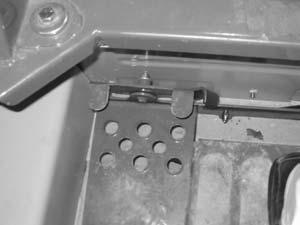
5.Fasten the loader to the hauling vehicle at the points indicated by the tie-down decals (Figure27 and Figure28).
6.Measure the clearance height of the loader and hauling vehicle. Post the clearance height in the cab of the vehicle.
Lifting the Loader
The loader can be lifted using a single-point or four-point lift kit, which is available from your Gehl dealer.
Warning
•Before lifting, check the lift kit for proper installation.
•Never allow riders in the operator’s compartment while the loader is lifted.
•Keep everyone a safe distance away from the loader while it is lifted.
•Loader may only be lifted with an empty bucket or empty pallet forks, or with no attachment. Never lift the loader with attachments other than those stated.
Lift equipment used and its installation is the responsibility of the party conducting the lift. All rigging MUST comply with applicable regulations and guidelines.
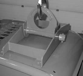
1.Using suitable lift equipment, hook into the lift eyes. Adjust the length of the slings or chains to lift the loader level.
Important: As needed, use a spreader bar to prevent the slings or chains from rubbing the sides of the ROPS/FOPS. (Fourpoint lift only)
Note: The loader my be slightly off level (10 degrees max.) when lifted, depending on loader model and attachment (single-point lift only.)
2.Center the hoist over the ROPS/FOPS. To prevent shock loading of the equipment and excessive swinging, slowly lift the loader off the ground. Perform all movements slowly and gradually. As needed, use a tag line to help position the loader.
Warning
Before servicing the machine, unless expressly instructed to the contrary, exercise the MANDATORY SAFETY SHUTDOWN PROCEDURE (page6). After service has been performed, be sure to restore all guards, shields and covers to their original positions before resuming operation.
This Service chapter details procedures for performing routine maintenance checks, adjustments and replacements. Most procedures are referred to in the Troubleshooting and Maintenance chapters of this manual. Refer to the Maintenance Interval Chart (page75) for service intervals. Refer to the separate engine manual for engine-related adjustments, lubrication and service procedures.
Note: All service procedures, except those described under the Dealer Services topic are owner-operator responsibilities.
Important: Always dispose of waste lubricating oils and hydraulic fluids according to local regulations or take to a recycling center for disposal. Do not pour onto the ground or down the drain.
Dealer Services
The following areas of component service, replacement and adjustments require special tools and knowledge for proper servicing and should be performed only by your authorized Gehl skid-steer loader dealer: hydrostatic drive components, hydraulic system pumps, valves, hydraulic cylinders, electrical components (other than battery, circuit breakers).
Replacement Parts
Air Cleaner Element, Primary184146

Air Cleaner Element, Secondary184195
Hydraulic Oil Filter Element074830
Engine Oil Filter Element132023
Fuel Filter Cartridge132024
Fresh Air Intake Filter (heater option)184708
Recirculation Air Filter (heater option)184709
Note: Part numbers may change. Your Gehl dealer will always have the latest part numbers.
Important: To ensure continued warranty coverage, only genuine Gehl replacement filters are to be used.
Loader Raising Procedure
To raise the skid-steer loader so all four (4) tires ARE NOT contacting the ground, use the procedure below:
Warning
Do not rely on a jack or hoist to maintain the raised position without additional blocking and supports. Serious personal injury could result from improperly raising or blocking the loader.
1.To block the loader, obtain enough solid wooden blocks, so that when stacked, all of the tires are raised off the ground.
2.Using a jack or hoist capable of lifting at the fully-equipped weight of the loader (with all attached options), lift the rear of the loader until the rear tires are off the ground.
3.Stack wooden blocks under the flat part of the loader chassis. They should run parallel with, but not touch, the rear tires.

4.Slowly lower the loader until its weight rests on the blocks. If the tires still touch the ground, raise the loader again, add more blocks and lower again.
5.Repeat Steps 2 through 4 for the front end. When the procedure is finished, all four tires are off the ground so they could be removed.
Loader Lowering Procedure
When service or adjustment procedures are complete, the loader can be lowered from the raised position. To lower the loader onto its tires:
1.Using a jack or hoist, raise the front of the loader until its weight no longer rests on the front blocks.
2.Carefully remove the blocking under the front of the loader.
3.Slowly lower the loader until the front tires are resting on the ground.
4.Repeat Steps 1 through 3 for the rear of the loader. When the procedure is finished, all four tires will be on the ground and the blocks removed from under the loader.
Engine Compartment Access
To open the engine compartment, lift the engine cover. Then pull the rear door latch and carefully swing open the rear door.
Tilting Back the ROPS/FOPS
The ROPS/FOPS is designed to protect the operator from flying objects and provide protection if the loader tips or rolls over, provided the operator is secured inside the ROPS/FOPS by the seat belt and restraint bar.
For service, unbolt the ROPS/FOPS and tilt it back slowly, moving the control handles out of the way. Two gas-charged springs help tilt it back. A self-actuating lock mechanism will engage to lock when the ROPS/FOPS in a rolled-back position. To lower the ROPS/FOPS apply upward force on it while pushing the lock mechanism handle toward the rear of the loader. Lower the ROPS/FOPS slowly onto the chassis, moving the control handles out of the way. Reinstall the anchor bolts, washers and locknuts.

Warning
Never operate the loader with the ROPS/FOPS removed or tilted back. Be sure the lock mechanism is securely engaged when the ROPS/FOPS is tilted back. Be sure to reinstall the anchor bolts, washers and locknuts before resuming operation.
Adjustments
Control Handles
The control handles do not require routine adjustment. Refer to the Service Manual for the initial setup procedure.
Fuel Sender
The fuel gauge sender, located on the fuel tank, sends a signal to the fuel gauge to indicate the amount of fuel in the fuel tank.
Check the fuel gauge sender periodically to ensure that the mounting screws are tight and that there is no fuel around the gasket. If service is required, apply an RTV or gasket sealant around the gasket when restoring the sender.
Engine Speed Control
The throttle does not require routine adjustment. Refer to the Service Manual for the initial setup procedure.
The throttle lever friction pad pressure can be adjusted if the throttle lever does not hold its position. Belleville washers and a lock nut on the throttle lever are used for making this adjustment.
Foreign Material Removal
The loader should be cleared daily of dirt and other foreign materials in the following areas:
•around the lift cylinders
•at the front of the loader
•on the hitch, especially around tilt cylinder
•around the hydraulic oil reservoir breather
•in the engine compartment
•in the operator’s compartment
Important: Build up of foreign materials in these areas can interfere with the operation of the loader, cause component damage or become a fire hazard.
Lubrication
Listed below are the temperature ranges and types of lubricants for this machine. Refer to the separate engine manual for more information regarding engine lubricants, quantities and grades required.
Note: Refer to the specific service sections for detailed information on periodic checking and replenishing of lubricants.
Refer to Figure33 for grease fitting locations. Wipe dirt from the fittings before greasing them to prevent contamination. Replace any missing or damaged fittings. To minimize dirt build-up, avoid excessive greasing.
Important: Always dispose of waste lubricating oils and hydraulic fluids according to local regulations or take to a recycling center for disposal. Do not pour onto the ground or down the drain.
SystemLubricant
Hydraulic System Oil
Chaincase Oil
Use Petro Canada HVI60, Mobil DTE 15M or equivalent which contains anti-rust, anti-foam and anti-oxidation additives, and conforms to ISO VG46.
Capacity: 4640/4840: 12 U.S. gallons (45 L)
5640/6640: 16 U.S. gallons (61 L)
Use hydraulic system oil or SAE grade 15W40 motor oil.
Capacity (each side): 8 U.S. quarts (7.5 L)
Grease Fittings Use lithium-based grease.
Below 32°F (0°C) – Use SAE Grade* 10W or 10W30
Above 32°F (0°C) – Use SAE Grade* 15W40
Engine Oil
*Service Classification: API – CH4
Capacity: 3 cylinder: 8.3 U.S. quarts (7.9 L)
4 cylinder: 11.5 U.S. quarts (10.8 L)
Figure33 Service Locations
Check Hydraulic Oil Level (page59)
Grease Lift Arm, Hitch, Cylinder Pivots and Latch Pins
Check Oil Level in Chaincases (page54)
Change Engine Oil and Filter (page58)
Change Hydraulic Oil Filter (page59)
Change Hydraulic Oil (page60)
Change Chaincase Oil (page54)
Check and Drain Water Separator o Perform the initial procedure at 50 hours, then at “l” or “t” intervals. v Severe operating conditions. t Perform the procedure at 1000 hours.
Chaincases
There is a chaincase on each side of the loader. Refer to the Maintenance Interval Chart (page75) for change intervals. Refer to the Lubrication chart (page53).
Checking and Adding Oil
1.Park the loader on a level surface. Stop the engine.
2.Remove the fill and check plug (Figure34) from each chaincase cover. The oil level should be at the plug level or no more than 1/4 in. (6 mm) below.
3.If the level is low, add fluid through the fill and check plug; (Figure34) until the oil level reaches the check plug hole. Reinstall the plug.
Draining Oil
1.Park the loader on a level surface, or on a sloping surface with the loader facing downhill and the tires blocked.
2.Remove the drain plug on each chaincase and drain the oil (Figure35) into a suitable container.
3.Reinstall and tighten the drain plugs.
4.Refill the chaincases at the fill plugs.
Drive Chains
Drive chains are located in the chaincase on each side of the machine. Refer to the Maintenance Interval Chart (page75) for tension check interval.
Checking Chain Tension
1.Raise the loader following the Loader Raising Procedure (page48).
2.Rotate each tire by hand. The proper amount of chain defection should be 1/8 in. to 1 in. (3 to 25 mm) forward and rearward. If the chain defection is more than 1in. (25 mm) or less than 1/8 in. (3 mm) in either direction, the chains should be adjusted.
Adjusting Chain Tension
1.Raise the loader following the Loader Raising Procedure (page48).
2.Remove the tire from the axle to be adjusted.
3.Loosen (but DO NOT remove) the bolts holding the axle to the chaincase.
4. Front Chain Tension – To tighten the front chain, move the front axle assembly toward the front of the loader. To loosen the chain, move the front axle assembly toward the rear of the loader.
Rear Chain Tension – To tighten the rear chain, move the rear axle assembly rearward. To loosen the chain, move the rear axle assembly toward the front of the loader.
5.After proper tension is achieved, retighten the bolts.
Important: Be careful not to over-tighten the drive chains. Over-tightening will cause premature drive chain and axle sprocket wear.
6.Reinstall the tire.
7.Repeat Steps 2 through 6 for any other axle requiring adjustment.
8.Lower the loader following the Loader Lowering Procedure (page49).
Engine Air Cleaner
Important: Failure to follow proper filter servicing instructions could result in catastrophic engine damage.
The air cleaner assembly consists of an outer (primary) filter element and an inner (secondary) filter element. An air filter restriction indicator for monitoring the condition of the elements is located on the front of the air cleaner. If the air filter becomes restricted, this indicator turns red to warn the operator that the air cleaner requires service. Push the reset button located at the end of the indicator after fitting a clean element. For replacement elements, refer to the Replacement Parts chart (page48).
Note: Before replacing the filter element(s), push the reset button on the indicator. Start the engine and adjust the throttle to full speed. If the indicator does not turn red, do not replace the element(s).
The outer element should be replaced only when the restriction indicator turns red. The inner element should be replaced every third time the outer element is replaced, unless the outer element is damaged or the inner element is visibly dirty. Along with a daily check of the restriction indicator, check that the air cleaner intake hose and clamps, and the mounting bracket hardware are properly secure.
Access
1.Open the engine cover and then the rear door (page49).
2.Unlatch the three latches on the air cleaner and remove the cover. Clean out any dirt built up in the cover assembly.
Outer Element
1.Carefully pull the outer element out of the housing. Never remove the inner element unless it is to be replaced.
2.Clean out any dirt built up in the housing. Leave the inner element installed during this step to prevent debris from entering the engine intake manifold.
3.Use a trouble light inside the outer element to inspect for bad spots, pinholes or ruptures. Replace the outer element if any damage is noted. The outer element must be replaced if it is oil- or soot-laden.
Note: Cleaning the outer element is not recommend.
Inner Element
Note: Replace the inner element only if it is visibly dirty or if the outer element has been replaced three times.
Before removing the inner element from the housing, clean out any dirt built up in the housing. Leave the inner element installed during this step to prevent debris from entering the engine intake manifold. Remove the inner element.
Reinstallation
1.Check the inside of the housing for any damage that may interfere with the elements.
2.Be sure that the element sealing surfaces are clean.
3.Insert the element(s), making sure that they are seated properly.
4.Secure the cover to the housing with the three clamps.
5.Check the hose connections and make sure they are all clamped and tightened properly.
6.Reset the indicator by pressing the reset button.
Note: Periodically inspect intake system tubes, rubber elbows and connections. Inspect for cracks, loose fits and loose clamps. Tighten or replace as needed. Intake system must be air tight.
Engine Service
Refer to the Maintenance Interval chart (page75) for change intervals. Refer to the Replacement Parts chart (page48) for filter part numbers.
Checking Engine Mounting Hardware
All bolts that secure the engine mounting brackets to the engine and the loader frame should be checked and re-torqued as necessary. Refer to the Torque Specifications chart (page93) for torque information.
Warning
Allow hot engine and hydraulic system components to cool before servicing.
Checking Engine Oil Level
Open engine cover (page49), pull out the dipstick and check the oil level. Markings on the dipstick represent FULL and LOW (add oil) levels.
Figure37 Engine Service Components
Changing Engine Oil and Filter
Note: For new units, the initial oil change should be after the first 50 hours. Important: Always dispose of waste lubricating oil according to local regulations or take to a recycling center for disposal; do not pour onto the ground or down the drain.
The loader has an engine oil filter located on the left side of the engine, in front of the battery. Follow the ROPS/FOPS procedure (page50) to lift up the ROPS/ FOPS and access the filter.
Note: Before removing the oil filter, remove the rear skid plate cover to drain the engine filter oil.

Access for draining the engine oil is located behind the left rear tire.
To add new oil, open the engine access cover. Remove the oil fill cap and add the recommended type and quantity of oil. Refer to the Lubrication chart, page52. Visually inspect the remote oil drain hose for damage or leaks.
Changing Fuel Filter
The loader has a fuel filter located on the left side of the engine, in front of the battery. Follow the ROPS/FOPS and Lock Mechanism procedure (page50) to lift up the ROPS and access the filter. Clamp off the fuel line to stop fuel flow BEFORE replacing the filter. Remove the spin-on filter cartridge. Install the new cartridge and check for leaks.
Hydraulic System

Refer to the Maintenance Interval chart (page75) for service intervals. Refer to the Replacement Parts chart (page48) for filter part numbers.
Warning
Before servicing the hydraulic system, be sure the lift arm is lowered.
Checking Hydraulic Oil Level
The loader has a sight gauge located at the right rear of the skid-steer loader inside the engine compar tment (Figure39). Check the fluid level with the lift arm lowered and the attachment on the ground.
Add hydraulic oil as required. Refer to the Lubrication chart (page52). Replace the fill cap.
Changing Hydraulic Oil Filter‘
To check the hydraulic filter element, run the engine at full throttle and normal operating temperature. Lift the engine access cover. Observe the hydraulic filter indicator located on the filter head (Figure40). If the indicator is green, the filter does not need replacing. If the indicator is red, replace the filter following the instructions below.
1.Turn off the engine.
2.Open the reservoir drain plug located on the inside bottom of the right riser.
3.Drain the oil out to a level below the point where the filter attaches to the reservoir.
4.Replace the reservoir drain plug.

5.Refill the hydraulic oil reservoir with oil. Refer to the Lubrication chart (page52).
6.Spin off the old hydraulic filter element and spin on the new filter element.
Changing Hydraulic Oil
The hydraulic oil must be replaced if it becomes contaminated, after major repairs and after 1000 hours or one year of use.
1.Install a catch pan of sufficient capacity under the oil reservoir, see page51.
2.Remove the drain plug located on the bottom front of the oil reservoir, behind the right rear tire. Allow the oil to drain.
3.Reinstall the drain plug.
4.Change the oil filter.
5.Refill the reservoir. Refer to the Lubrication topic (page51).
6.Start the engine and operate the hydraulic controls.
7.Stop the engine and check for leaks at the filter and reservoir drain plug.
8.Check the fluid level and add fluid if needed.
Bucket Cutting Edge
The bucket cutting edge should be replaced when it is worn to within 1in. (25mm) of the bucket body.
Alternator/Fan Belt
Refer to the separate engine manual for setting proper belt tension. If the belt is worn, cracked or otherwise deteriorated, replace the belt following the procedure in the engine manual.
Wheel Nuts
Wheel nut torque must be checked before initial operation and every two hours thereafter until the wheel mounting hardware torque remains at 180ft-lbs (244N·m). When wheels are removed and reinstalled this procedure must be repeated.
Lift Arm Pivots
The All-Tach pivot should be torqued periodically to 240 ft-lbs (325 N·m). Refer to the Maintenance Interval chart (page75).
Cooling System
Important: Check the cooling system daily to prevent overheating, loss of performance and engine damage.
Cleaning the Cooling System
Allow sufficient time for the oil cooler to cool before working on or near it. Parts get extremely hot during operation and can burn you.
The oil cooler assembly is mounted between the engine and the hinged rear door. When operating correctly, air is blown through the openings between the fins by the engine fan. During operation dust and debris can build up on the engine side of the oil cooler and restrict air flow through the fins. To remove this restriction, use compressed air or a water hose and direct the flow through the fins from the rear of the cooler towards the engine.
Tires
Inflating or servicing tires can be dangerous. When possible, trained personnel should service and mount tires. To avoid possible death or serious injury, follow the safety precautions below.
To keep tire wear even, rotate the tires from front to rear and rear to front.
It is important to keep the same size tire on each side of the loader to prevent excessive wear on tires, chains, or other damage. If different sizes are used, tires will be turning at different speeds, causing excessive wear.
Note: The tread bar of all tires should face the same direction.
BE SURE the rim is clean and free of rust.
Lubricate the tire beads and rim flanges with a soap solution. Do NOT use oil or grease.
Use a clip-on tire chuck with remote hose and gauge, allowing you to stand clear while inflating the tire.
NEVER inflate beyond 35 psi (240 kPa) to seat the beads. If the beads have not seated by the time the pressure reaches 35 psi (240 kPa), deflate the assembly, reposition the tire on the rim, lubricate both parts and re-inflate. Inflation pressure beyond 35 psi (240 kPa) with unseated beads may break the bead or rim with explosive force sufficient to cause death or serious injury. After seating the beads, adjust the inflation pressure to the recommended operating pressure.
Do NOT weld, braze or otherwise attempt to repair and use a damaged rim.
Checking Tire Pressure
Correct tire pressure should be maintained for all tires to enhance operating stability and extend tire life. Refer to the charts below for proper inflation pressures.
Heater Filters
Loaders with the optional heater or heater/air conditioner include two filters: fresh air intake and Recirculation air.
Refer to the Replacement Parts topic (page48) for filter part numbers. Filters should be replaced as needed.
Fresh Air Intake Filter: Located on the backside of the main unit. Tilt back the ROPS/FOPS for access and slide out the filter.
Recirculation Air Filter: Located on the front of the ROPS/FOPS rear deck panel. Remove four screws and pull out the filter.
Note: Keeping the cab clean will reduce need for service and help ensure proper air conditioner and heater operation. Failure to do so can cause evaporator and heater core plugging, fan noise, vibration and failure.
Electrical System
Circuit Breakers
The circuit breakers for the inside electrical system are located on the right instrument panel.
Battery
Before servicing the battery or electrical system, be sure the battery disconnect switch is in the OFF position.
The battery on the loader is a 12-volt, wet cell battery. To access the battery, open the engine access cover, unlatch and open the rear grille.
The battery top must be kept clean. Clean it with an alkaline solution (ammonia or baking soda and water). After foaming has stopped, flush the battery top with clean water. If the terminals and cable connection clamps are corroded or have a build-up, disconnect the cables and clean the terminals and clamps with the same alkaline solution.
Warning Warning
Explosive gas is produced when a battery is in use or being charged. Keep flames or sparks away from the battery area. ALWAYS charge the battery in a well-ventilated area.
Never lay a metal object on top of a battery, because a short circuit can result.
Battery acid is harmful on contact with skin or fabrics. If acid spills, follow these first-aid tips:
1.Immediately remove any clothing on which acid spills.
2.If acid contacts the skin, rinse the affected area with running water for 10 to 15 minutes.
3.If acid contacts the eyes, flood the eyes with running water for 10 to 15 minutes. See a doctor at once. Never use any medication or eye drops unless prescribed by the doctor.
4.To neutralize acid spilled on the floor, use one of the following mixtures: a.1 pound (0.5 kg) of baking soda in 1 gallon (4 L) of water, or b.1 pint (0.5 L) of household ammonia in 1 gallon (4 L) of water
Whenever the battery is removed, be sure to disconnect the negative (-) battery terminal connection first.