16 minute read
Pre-Start Walk-Around Inspection Illustration

PRE-START WALK-AROUND INSPECTION PROCEDURE
Refer to the following illustration and checklist to perform the inspection. Begin with item 1 at the left front of the machine and walk toward the rear of the machine on the left side and around the back and toward the front on the right side of the machine.
Any needed repairs or service noted during the inspection must be performed by a qualified service technician before operating the machine.
The illustration and checklist page can be copied for future pre-start walk-around inspections.

Pre-Start Walk-Around Inspection Checklist
o1.Attachment Tool: Check for broken missing or damaged parts. When utilizing forks, check for welds, cracks or misalignment. Replace the forks in sets when the condition of the fork(s) is questionable.
IMPORTANT: DO NOT use forks that have been repaired by welding.
o2.Attachment Tool Mount: No loose or missing parts; no visible damage.
o3.Attachment Tool Mounting Pins: No visible damage; pin fit is secure and properly lubricated.
o4.Boom Section and Wear Pads: No loose or missing parts; no visible damage; no excessive wear.
NOTE: Wear pads that measure 3/8” (9.5 mm) thick or less need to be replaced.
o5.Boom Angle Indicator: Looseness; no visible damage; bubble is visible.
o6.Tire and Wheel Assemblies: Properly secured; no loose or missing lug nuts; no visible damage (cuts or abrasions); proper tire inflation.
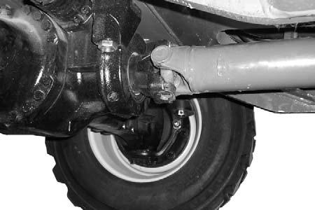
o7.Front and Rear Axles: No loose or missing parts; no visible damage; tie rod end studs locked; properly lubricated.
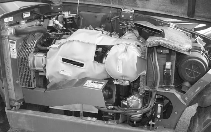
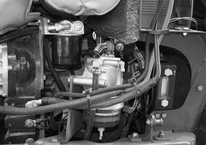
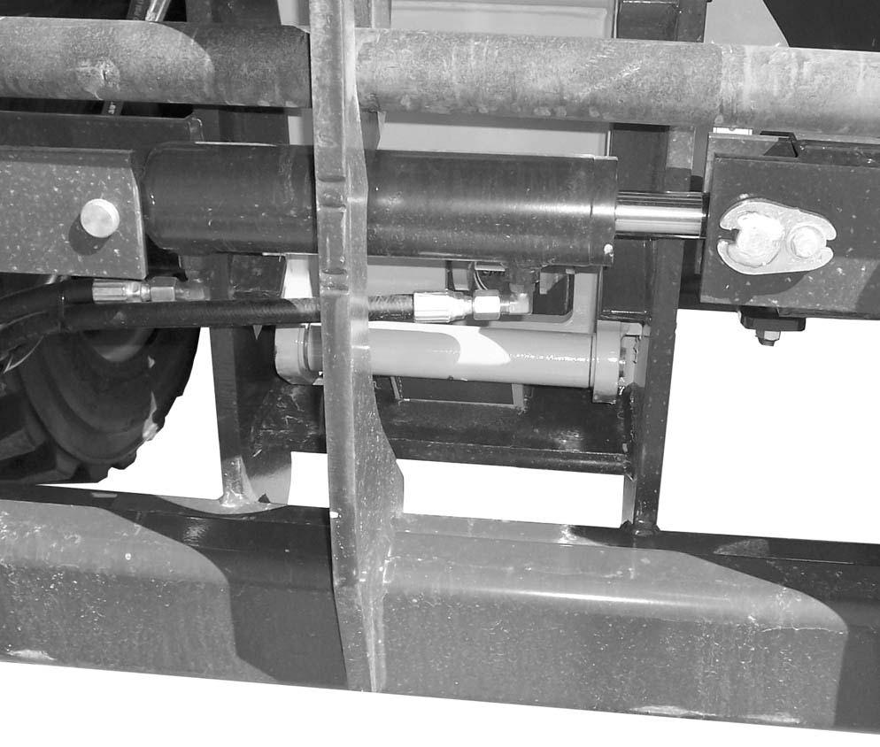
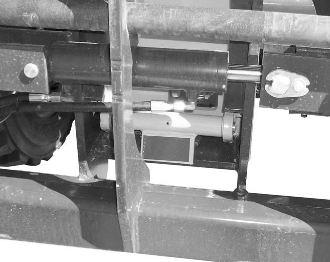
o8.Operator Compartment: o Seat belt undamaged; operates properly; mounting hardware secure. o Switches and levers undamage; o no loose or missing parts; o load charts properly secured and legible; o levers and switches operate properly; control markings legible; o frame level indicator secured and undamaged, bubble is visible. o9.Boom Hydraulic Hoses: No visible damage or exterior wear; no evidence of leaking. o10.Slave Cylinder: Properly secured; no visible damage; no evidence of leaking from the cylinder; properly lubricated. o11.Rear Light Assemblies (when equipped): Properly secured; no visible damage; no loose or disconnected wires; function properly. o12.Fuel Tank: No damage or leaking; breather cap secure and working. o13.Boom Pivot Assembly: Properly secured; no visible damage or excessive wear; properly lubricated. o14.Covers, Doors and Latches: All covers doors and latches are in working condition; properly secured with no loose or missing parts; all components operate properly. o15.Engine Compartment: o Engine oil level, add if needed. o Coolant level, add if needed. o Hydraulic oil level, add if needed. o No evidence of engine oil, hydraulic oil or coolant leaks. o Hydraulic Cooler and Radiator: No loose or missing parts; no visible damage. o Belts and hoses in good condition, properly secured and adjusted. o Exhaust System: No loose or missing parts; no visible damage; no obstructions to the outlet. o Engine Air Cleaner: No loose or missing parts; no obstructions to the inlet. o Battery: No loose or broken cables; no damage or corrosion. o16.Hydraulic Control Valve Assembly: (located under the boom on side of operator station) No loose or missing parts; not leaking; no damaged or leaking hoses. o17.Hydraulic Oil Reservoir: (located under the boom in the center of the frame) No evidence of leaking; breather cap working and secure. o18.Lift Cylinder: Properly secured; no visible damage; no evidence of leaking from the cylinder; properly lubricated. o19.Mirror Assembly: No visible damage; adjusted properly. o20.Frame: No cracks or visible damage. o21.Tilt and Auxiliary Hydraulic Hoses: (Auxiliary hoses are optional and not shown on this machine) No damage or excessive wear; no evidence of leaking. o22.Attachment Tilt Cylinder: Properly secured; no visible damage; no evidence of leaking from the cylinder; properly lubricated.
Before Starting Engine
Before mounting the operator’s compartment, walk completely around the machine to be sure no one is under, on, or close to it. Let others in the area know you are going to start up and wait until everyone is clear of the machine.
Before starting the engine and running the machine, refer to the Indicators and Controls chapter and become familiar with the various operating controls, indicators and safety features.
Starting The Engine
The following procedure is recommended for starting the engine:
1.Grasp the hand holds to step up into the operator’s compartment.
2.Adjust the seat and fasten the seat belt.
Warning
ALWAYS fasten your seat belt before starting the engine. Leave the parking brake applied until the engine is running and you are ready to operate the machine.
3.Check that all controls are in their “neutral” positions, except the parking brake switch, which should be in the “ON” position.
Warning
Do not use starting fluid (ether) with engine preheat systems. An explosion can result, which can cause engine damage, injury or death.
4.Turn the key switch to “ON” position. The preheat indicator on the multi-function display will be “ON” indicating the pre-heater is in use. When the indicator goes out, the engine can be started.
NOTE: The engine pre-heater is used to assist starting in cold weather conditions. The indicator may stay lighted for 3-30 seconds depending on the temperature. If you are operating the telescopic handler in normal or warm weather conditions, the pre-heat indicator will go out in several seconds and you can start the engine.
5.Press the start button on early models or turn ignition switch on late model to start the engine. Release the button or ignition switch as soon as the engine starts. If the button or ignition switch is released before the engine starts, turn the keyswitch to “OFF” position and allow the starter to stop before attempting to start again.
IMPORTANT: Crank the starter until the engine starts. If the engine fails to start within 15 seconds, return the key to the “OFF” position, wait at least 30 seconds, and try again to start the engine. Cranking the engine for longer than 15 seconds will result in premature failure of the starter.
6.After the engine starts, allow a sufficient warm-up time before operating the controls.
NOTE: When the parking brake switch is pressed into the “OFF” position, the parking brake will remain applied until the travel lever is placed into either “Forward” or “Reverse.”
7.Check that indicators are in normal condition.
8.Check that there are no fuel, oil or engine coolant leaks, and no abnormal noises or vibrations.
Cold Starting
A optional block heater is recommended for starting in temperatures of 20oF (-7oC) or lower.
The block heater should be connected to an AC power supply several hours prior to starting the engine depending on the ambient temperature.
Warning
Do not use starting fluid (ether) with engine preheat systems. An explosion can result, which can cause engine damage, injury or death.
If the battery becomes discharged and does not have sufficient power to start the engine, jumper cables can be used for starting assistance. Refer to the jump starting instructions in the Service and Storage chapter of this manual for safe jump starting procedures.
Stopping
The following procedure is the recommended sequence for stopping the machine:
1.Bring the machine to a stop on a level surface. Avoid parking on a slope, but if necessary, park across the slope and block the tires.
2.Fully retract the boom and lower the attachment to the ground. Idle the engine for 5 minutes to allow engine components to cool slightly before shutting the engine down.
3.Place controls in neutral. Apply the parking brake.
4.Turn the ignition switch key to the “OFF” position. Remove the key.
5.Unfasten the seatbelt, and grasp the hand holds while climbing out of the operator’s compartment.
First Time Operation
Make sure the engine is warm and then go through the following procedures:
Caution
Be sure the area used for test-running is clear of spectators and obstructions. Initially, operate the machine with an empty attachment tool.
Select the travel direction. Switch off the parking brake and move ahead slowly, while testing the steering and brakes. Stop and operate all boom and attachment tool function controls, checking for smooth response.
Apply the service brakes, stop the machine and move the travel lever to the opposite direction.
IMPORTANT: To prevent damage to the transmission, the Telescopic Handler should be stopped or traveling at a slow speed and not accelerating when changing the direction of travel.
Exhaust Filter Cleaning System
The engine is equipped with an exhaust filter in place of a muffler. This filter is located to the front of the engine under the engine cover. This exhaust filter reduces carbon monoxide, hydrocarbons, and particulate matter from the exhaust stream. Trapped particles are eventually oxidized through a process known as regeneration or exhaust filter cleaning.
Under normal machine operation and with the system in AUTO mode, the exhaust filter requires minimal operator interaction.
To avoid unnecessary buildup of diesel particles or soot in the exhaust filter system;
1.Utilize the Automatic (AUTO) Exhaust Filter Cleaning mode.
2.Avoid unnecessary idling.
3.Use the proper engine oil. See Lubrication chapter of this manual or the engine maual for proper engine oil specifications.
4.Use only ultra low sulfur diesel (ULSD) fuel. See Lubrication chapter of this maual or the engine manual for fuel requirements.
Even with proper maintenance, ash and soot will build up in the exhaust filter after several thousand hours of operation and require service. This service will need to be performed by a authorized Gehl dealer.
Automatic (AUTO) Exhaust Filter Cleaning
Operating the engine in AUTO Mode allows the ECU to perform intelligent exhaust cleaning as required. The Exhaust Filter Cleaning Indicator will illuminate when the system is actively performing an exhaust filter cleaning. When the exhaust filter cleaning process has completed its cycle, the cleaning indicator will turn off.
The machine can be operated as normal during the auto exhaust filter cleaning process unless the operator determines the machine is not in a safe location for high exhaust temperatures and disables the auto cleaning process.
To enable the auto exhaust filter cleaning mode, the exhaust filter cleaning rocker switch should be in the center position.
IMPORTANT: It is recommended that the exhaust filter cleaning be in the Auto mode at all times. Auto mode should only be disabled when the machine is not in a safe location during the exhaust filter cleaning process.
If the machine is not able to be moved to a safe location, the operator should temporarily disable auto exhaust filter cleaning. If the machine is located in a safe location, the auto mode should always be enabled.
Warning
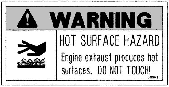
During auto or manual exhaust filter cleaning operations, the engine will run at elevated idle and hot temperatures for approximately 30 minutes. Exhaust gases and exhaust filter components reach temperatures hot enough to burn people, ignite, or melt common materials.
Servicing the machine or attachments during exhaust filter cleaning can result in serious personal injury. Avoid exposure and skin contact with hot exhaust gases and components.
If the machine is not in a safe location for elevated temperatures, move the machine to a safe location and check for adequate fuel level before beginning the exhaust filter cleaning process.
Manual/Parked Exhaust Filter Cleaning
Manual/Parked exhaust filter cleaning is initiated by the operator. This process allows the system to clean the exhaust filter when the operator previously needed to disable the auto exhaust cleaning process because of specific conditions. During this process the engine speed will be controlled by the ECU. The machine must remain parked during this process.
NOTE: It is not necessary to perform a manual/parked exhaust cleaning unless a previous auto cleaning process was cancelled and the indicator in the exhaust filter gauge is illuminated.
Cleaning times will vary depending upon several specific criteria. The average standard cleaning time can range from 20 - 50 minutes or longer.
To enable manual/parked exhaust filter cleaning;
1.Park the machine in a safe location and check that the machine has a recommended 1/4 tank of fuel to complete the process.
2.Reduce engine speed to low idle and apply the parking brake.
3.Press the top of the exhaust filter cleaning switch for approximately 3 seconds until the indicator in the switch illuminates. The cleaning indicator in the exhaust filter gauge will also illuminate.
The indicators will go off when the exhaust filter cleaning process is completed. If the machine is not going to be returned to service immediately after the cleaning process, allow the engine and the exhaust filter time to return to normal operating temperature before stopping the engine. The manual/parked filter cleaning process can be canceled at any time during the process.
Avoid disabling the cleaning process unless absolutely necessary. Repeated disabling or ignoring prompts to perform a manual/parked cleaning procedure will cause additional engine power limitations and can eventually lead to dealer required service.
Utilize AUTO Exhaust Filter Cleaning mode to avoid additional service.
Disable Exhaust Filter Cleaning
Disabling the exhaust filter cleaning request is not recommended. Disable the automatic exhaust filter cleaning only when necessary. Whenever possible, cleaning should be allowed and the exhaust filter cleaning switch should be left in the AUTO Mode. When left in auto mode, soot buildup in the exhaust filter system will be at a minimum.
To disable exhaust filter cleaning, press the bottom of the exhaust filter cleaning rocker switch. The Auto Cleaning Disabled Indicator located in the exhaust filter gauge will be illuminated.
Exhaust Filter Cleaning Precautions
When the AUTO Exhaust Filter Cleaning is disabled, the sytem has 3 levels of notification to advise the operator to perform the exhaust filter cleaning. The 3 levels are as follows;
1.The Exhaust Filter Indicator will illuminate, indicating the the soot level in the filter is slightly high. If conditions are safe, the operator should enable auto exhaust filter cleaning or perform a manual exhaust filter cleaning.


2.The Exhaust Filter Indicator and the Amber Alert Indicator in the exhaust filter gauge will illuminate. The engine performace will be reduced by the ECU because the soot level in the exhaust filter is moderately high. If conditions are safe, the operator should enable auto exhaust filter cleaning. If conditions are not safe, the operator should move the machine to a safe location and either enable the auto exhaust filter cleaning or perform a manual exhaust filter cleaning.
3.The Exhaust Filter Indicator and the Red Alert Indicator in the exhaust filter gauge will illuminate. The ECU will further reduce engine performance. Continuing to operate the machine at this level will set a “Service Only” soot condition where the engine cannot clean the exhaust filter itself. In this condition, contact your authorized Gehl dealer.
Parking Brake
NOTE: The parking brake mechanism within the front axle is not designed for, and not intended to be used as, the primary means of stopping movement of the machine. Hydraulic braking provided through the service brakes within the front axle is the primary means for stopping movement.
The proper sequence for correct machine operation is to always engage the parking brake switch before shutting off the engine; and to disengage the parking brake ONLY after the engine is running. In an EMERGENCY, if it becomes necessary to STOP movement, activate the parking brake switch to “ON.”
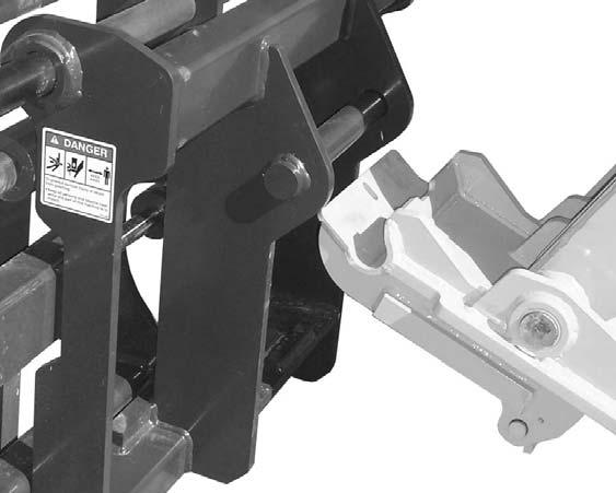
Changing Attachment Tools
The Telescopic Handler boom nose will accept Gehl Quick-attach System attachment tools. The Quickattach System has a quick-release hookup and locking mechanism for mounting framing-type or masonrytype attachment tools to the boom nose.
Attaching
To pick up the attachment tool, proceed as follows:
1.Raise the boom slightly, extend it 2 to 3 feet (600900 mm) for better visibility, and tilt the Quickattach System forward.
2.Align the Quick-attach System squarely with the back of the attachment tool.
3.Slowly extend the Quick-attach System and lower the hooks under the attachment tool hookup bar.
4.Tilt the Quick-attach System back so that the lock plate engages the attachment tool. This secures the attachment tool to the Quick-attach System. Verify the attachment tool is properly secured by tilting the tool sufficiently forward such that it does not hinge away from the tool carrier.
5.For an attachment tool with auxiliary hydraulics, connect hoses to the quick-disconnect connectors on the boom nose.
Detaching
To detach attachment tool, proceed as follows:
1.Raise the boom slightly and extend it 2 to 3 feet (600-900 mm) for better visibility. Lower the boom until the attachment tool is approximately 12” (300 mm) off the ground.
2.Roll the carrier rearward as far as it will go. When the carrier is rolled all the way back, perform the Mandatory Safety Shutdown Procedure (p. 8, Safety chapter).
3.With the engine off, leave the operator’s station. Manually raise the lock spring, and flip the lock plate up and outward at least 180° so it is in position to re-lock on the next attachment tool.
4.Tilt the Quick-attach System forward to allow the attachment tool to roll out, then lower the boom so the hook ears clear the hookup bar on the attachment tool.
NOTE: One side of the lock plate has a bright red decal to indicate the unlocked position.
5.If the attachment tool has auxiliary hydraulics, disconnect the hoses from the quick-disconnects on the boom nose.
6.Start the engine and tilt the Quick-attach System forward, then slowly back the machine until the attachment tool is free from the boom nose.
Warning
Modifications, alterations to, or use of attachment tools not authorized by Gehl (or the manufacturer) in writing can void warranty and cause machine damage and/or serious personal injury or death.
SELF-LEVELING
The machine is equipped with a hydraulic self-leveling feature. This feature is designed to keep the attachment tool level while the boom is being raised and lowered.
Machine Operation With Solid Rubber Tires
Solid rubber tires are designed for intermittent service and limited running distances. The Working Day Average Speed should not exceed 3 mph at an average load of 75% of maximum capacity. Telehandlers equipped with solid rubber tires should not be used in applications requiring speeds over 15 mph, or continuous journeys over 1 mile when loaded at or above 50% of capacity. In the event an application requires vehicle speeds over 15 mph, excessive roading, or driving extended distances while loaded, Gehl recommends the use of other approved tire options.
General Machine Operation
Check the Telescopic Handler to be sure all systems are in good operating condition. Perform the following steps before starting the machine the first time each day:
Warning
Exhaust fumes can kill. Ensure proper ventilation when starting indoors or in enclosed areas.
Use proper hand holds, NOT the steering wheel or control levers when mounting and dismounting.
NEVER operate the machine with safety guards or covers removed.
Over-inflated tires can explode and cause injury or death. Tire repairs MUST be made only by authorized personnel using proper tools and equipment.
1.Check the engine oil, coolant and hydraulic oil levels.
2.Check hydraulic oil cooler and engine radiator for debris.
3.Be sure weekly lubrication has been done.
4.Visually inspect for leaks and broken or malfunctioning parts. Be sure all caps, covers and safety shields are in place.
5.Check tires for cuts, bulges, nails, correct pressure, loose wheel nuts, etc.
6.Inspect the work area. Be sure you know where you will make load pickups, lifts and turns. Look over the terrain of the jobsite for holes, obstacles, slippery surfaces, and soft or deep mud.
7.Check clearances of ramps, doorways and passage-ways. Check overhead clearances if you will travel and place loads near power or telephone lines.
If the machine is in need of repair or in any way unsafe, or contributes to an unsafe condition, the matter must be reported immediately to the user’s designated authority. The machine must NOT be operated until it has been restored to a safe operating condition.
Operate the travel controls gradually and smoothly when starting, stopping, turning and reversing direction.
Grade and Slope Precautions
The Telescopic Handler complies with industry stability test requirements and is stable when properly operated. However, improper operation, faulty maintenance, and poor housekeeping can contribute to a condition of instability and defeat the purpose of the standard.
The amount of forward and rearward tilt to be used is governed by the application. Although use of maximum rearward tilt is allowable under certain conditions, such as traveling with the load fully lowered, the stability limits of the machine, as determined by the industry standard tests, do not encompass consideration for excessive tilt at high elevations, or the handling of off-center loads.
Only handle loads within the capacity limits of the machine, and which are stable and safely arranged. When attachments are used, extra care should be taken in securing, manipulating, positioning and transporting the load.
Grade Limits
NOTE: Grade limits are based on ANSI/ITSDF standard B56.6-2005.
This Telescopic Handler meets or exceeds the safety standard (ANSI/ITSDF B56.6) stability limits for rough terrain forklifts. The stability tipping limits cover specific, controlled test conditions, which are extremes, and which are not intended to be achieved during normal worksite operations. The following specifications are provided only as information to the operator, and must not be used as a guideline for operating the Telescopic Handler. For safe operation, always follow the instructions and warnings provided in this manual.
Warning
DO NOT level the frame with the boom raised or extended. Only level the frame while stopped, and with the boom fully retracted, and the attachment tool raised just enough to clear the ground.
1.DO NOT place or retrieve loads on an up or down slope or grade that exceeds 7% or 4°.
2.DO NOT travel up or down a grade or slope that exceeds 22% or 12° while loaded.
3.DO NOT place or retrieve loads on a side hill with a slope or grade that exceeds 12% or 7°. Check the location of the ball in the frame angle indicator located on the ROPS/FOPS cross member. If the ball in the frame angle indicator is in the green zone, it is safe to place or retrieve the load. If the ball in the frame angle indicator is in the yellow zone, use slower movements and extra caution to ensure remaining within the limits of the load chart, because the machine is nearing an unstable condition. If the ball in the frame angle indicator is in the red zone, loads cannot be placed or retrieved.
4.DO NOT travel across a side hill that exceeds 18% or 10° grade. Check the frame angle indicator on the ROPS/FOPS cross member to determine the angle of the grade. The attachment tool MUST be maintained at the “carry” position, with the boom fully retracted and attachment tool at minimum ground clearance.
When ascending or descending grades in excess of 5% or 3°, the machine should be driven with the load upgrade. An unloaded machine should be operated on all grades with the load handling attachment tool downgrade, tilted back if applicable, and raised only as far as necessary to clear the ground surface.
Avoid turning if possible and use extreme caution on grades, ramps and inclines. Normally travel straight up and down the slope.
Traffic Flow Patterns
Know and understand the traffic flow patterns of your jobsite. Know all Telescopic Handler hand signals for safety. Use signal persons as necessary for safe operation, and be sure you can see the signal person and acknowledge the signals given.