26 minute read
SAFETY


The above Safety Alert Symbol means ATTENTION! BECOME ALERT!
YOUR SAFETY IS INVOLVED! It stresses an attitude of ‘‘Heads Up for Safety’’ and can be found throughout this Operator’s Manual and on decals on the machine.
Before you attempt to operate this equipment, read and study the following safety information. In addition, be sure that every one who operates or works with this equipment, whether family member or employee, is familiar with these safety precautions. It is essential to have competent and careful operators, who are not physically or mentally impaired, and who are thoroughly trained in the safe operation of the machine and the handling of loads. It is recommended that the operator be capable of obtaining a valid motor vehicle operator’s license.
Use of this machine is subject to certain hazards that cannot be eliminated by mechanical means, but only by exercising intelligence, care and common sense. Such hazards include, but are not limited to, hillside operation, overloading, instability of the load, poor maintenance and using the equipment for a purpose for which it is not intended or designed.
Gehl Company ALWAYS takes the operator and his/her safety into consideration when designing machinery and guards exposed moving parts. However, some areas can not be guarded or shielded in order to assure proper operation. Furthermore, this Operator’s Manual and decals on the machine warn of additional hazards and should be read and observed closely.
Some photographs used in this manual may show doors, guards and shields open or removed for illustration purposes ONLY. BE SURE that all doors, guards and shields are in their proper operating positions BEFORE starting the engine to operate the unit.
Different applications may require certain optional safety equipment, such as a back-up alarm, horn mirror or strobe light. BE SURE you know the job site hazards and equip your machine as needed.
Danger
‘‘DANGER’’ indicates an imminently hazardous situation which, if not avoided, will result in death or serious injury.
Warning
‘‘WARNING’’ indicates a potentially hazardous situation which, if not avoided, could result in death or serious injury.
Caution
‘‘CAUTION’’ indicates a potentially hazardous situation which, if not avoided, may result in minor or moderate injury. May also alert against unsafe practices.
Mandatory Safety Shutdown Procedure
BEFORE leaving the operator’s seat:
1.Move directional control to ‘‘neutral’’ position.
2.Move the throttle to low idle position.
3.Lower lift arm completely and place attachment flat on the ground. However, if the lift arm MUST be left in the “raised” position, BE SURE to properly engage the lift cylinder mechanical lock.
4.Apply the parking brake.
5.Unfasten seat belt, shut off engine, and remove key.
ONLY when you have taken these precautions can you be sure it is safe to proceed. Failure to follow the above procedure, could lead to death or serious bodily injury.
SAFETY REMINDERS Before Starting
• DO NOT modify the ROPS/FOPS unless instructed to in installation instructions. Modifications such as welding, drilling or cutting can weaken the structure and reduce the protection it provides. A damaged ROPS/FOPS cannot be repaired – it must be replaced.
• To ensure continued safe operation, replace damaged or worn-out parts with genuine Gehl service parts, BEFORE operating this equipment.
• Gehl loaders are designed and intended to be used only with Gehl attachments or a approved referral attachments. Gehl cannot be responsible for operator safety if the loader is used with a non-approved attachment.
• Remove all trash and debris from the machine each day, especially in the engine compartment, to minimize the risk of fire.
• Always face the loader and use the hand holds and steps when getting on and off the loader. Do not jump off the loader.
• NEVER use starting fluids (ether).
• Walk around the machine and warn all nearby personnel before starting the machine.
• All Always perform a daily inspection of the machine before using it. Look for damage, loose or missing part, leaks, etc. Be sure all fluid levels are at the proper level for operation and all guards and shields are in place.
• REMEMBER, it is the owner’s responsibility for communicating information on the safe use and proper maintenance to users of this machine.
During Operation
• The terrain, engine speed, load being carried and abrupt control movements can affect machine stability. IF MlSUSED, ANY OF THE ABOVE FACTORS CAN CAUSE THE LOADER TO TIP, THROWING YOU FORWARD OR OUT OF THE UNIT, CAUSING DEATH OR SERIOUS BODILY INJURY. Therefore, ALWAYS wear the seat belt. Operate the controls smoothly and gradually at an appropriate engine speed that matches the operating conditions.
• Always travel with the heavier end of the loader in the same direction as the top of the incline for additional stability when operating on inclines or ramps.
• DO NOT raise or drop a loaded bucket or fork suddenly. Abrupt movements under load can cause serious instability.
• DO NOT drive too close to an excavation or ditch; BE SURE that the surrounding ground has adequate strength to support the weight of the loader and the load.
• NEVER carry riders. Do not allow others to to ride on the machine or attachments, because they could fall or cause an accident.
• Always look to the rear before backing up the loader.
• Operate the controls only from the operator’s seat.
• Always keep hands and feet inside the operator’s compartment while operating the machine.
• New operators must practice operate the loader in an open area away from bystanders. Practice with the controls until the loader can be operated safely and efficiently.
• Exhaust fumes can kill. Do not operate this machine in an enclose area unless there is adequate ventilation.
• When you park the machine and before you leave the seat, apply the parking brake.
Maintenance
• DO NOT attempt to remove the radiator cap after the engine has reached operating temperature or if it is overheated, because the engine coolant will be extremely HOT and under pressure. ALWAYS wait for the engine to cool BEFORE attempting to relieve pressure and remove the radiator cap. Failure to heed could result in severe burns.
• NEVER use your hands to search for hydraulic fluid leaks. Use a piece of paper or cardboard. Escaping fluid under pressure can be invisible and can penetrate the skin and cause serious injury. If any fluid is injected into your skin, see a doctor at once. Injected fluid MUST be surgically removed by a doctor familiar with this type of injury or gangrene may result.
• ALWAYS wear safety glasses with side shields when striking metal against metal. In addition, it is also recommended that a softer (non-chipable material) be used to cushion the blow. Failure to heed could lead to serious injury to the eyes or other parts of the body.
• ALWAYS wear eye protection when servicing the unit. Wear a hard hat or other protection as needed.
• ALWAYS “jump” start a unit using the procedure described in the Service chapter of this manual.
• NEVER charge a frozen battery.
• Lead acid batteries produce flammable and explosive gases. Keep electrical arcs, sparks, flames and smoking materials away from the battery.
• Battery acid causes severe burns. In case of acid contact, immediately wash with water and seek medical attention.
• DO NOT smoke while filling the fuel tank or while working on the fuel or hydraulic systems.
• NEVER by-pass the keyswitch to start the loader engine. Only use the jump-starting procedure detailed in the Service chapter of this manual.
Transporting
• If the loader is transported, BE SURE to properly install the steering frame lock as described in the Operation chapter of this manual.
CHAPTER 5 CONTROLS & SAFETY EQUIPMENT WARNING
Become familiar with ALL safety devices and controls on the loader BEFORE operating it. Know how to stop loader operation BEFORE starting it. This loader is designed and intended to be used ONLY with mounted Gehl Company attachments, or Gehl Company approved accessory or referral attachments. The Gehl Company cannot be responsible for operator safety if the loader is used with an unapproved attachment.
GUARDS & SHIELDS
Whenever possible and without affecting loader operation, guards and shields are used to protect potentially hazardous areas. In many places, decals are also provided to warn of potential hazards and to display operating procedures.
Warning
Read and understand ALL safety decals on the loader BEFORE operating it. DO NOT operate the loader unless ALL factory-installed guards and shields are properly secured in place.
HAND THROTTLE (Fig. 1)
A hand-operated throttle lever is provided to control the engine RPM to match power requirements. The lever is friction-controlled to stay at the selected throttle setting. Lifting up on the throttle lever increases the engine RPM and lowering the throttle lever decreases the RPM.
Warning
ALWAYS be sure that all controls are in their “neutral” positions BEFORE starting the engine. Operation of the controls should be smooth. Excessive travel speed and quick control movements are hazardous and could cause an accident.
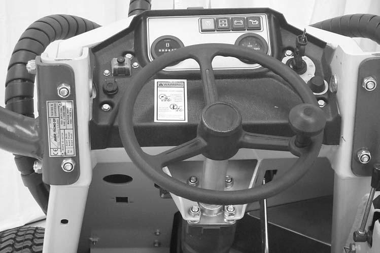
DIRECTIONAL CONTROL PEDALS (Fig. 1)
The directional control pedals are linked to the hydrostatic drives. Depress the right side foot pedal to move the loader forward or depress the left side pedal to move the loader rearward. Turn the steering wheel slowly clockwise to turn right and counterclockwise to turn left.

Warning
When turning with the loader, BE SURE to maintain adequate side clearance, because the operator’s seat can extend beyond the turning radius of the wheels.
PARKING BRAKE (Fig. 1)
The loader is furnished with a hand-operated parking brake. The parking brake handle is linked by cable to the brake assembly.
IMPORTANT: When parking brake is disengaged, you MUST travel in reverse to fully disengage the parking brake pin from the drive sprocket. It also may be necessary to rock the loader back and forth to release the pin. Failure to do so will damage the pin.
Warning
The parking brake MUST BE applied any time the loader is parked on a grade. If the parking brake is NOT applied, the loader can start to roll after the drive motors drain down. Failure to heed could result in death or serious injury.
Warning
Function and adjustment of the parking brake should be checked regularly to maintain proper operation at all times. NEVER use the parking brake as a means of checking hydrostatic torque, as this will cause the brake pins to shear and result in parking brake failure.
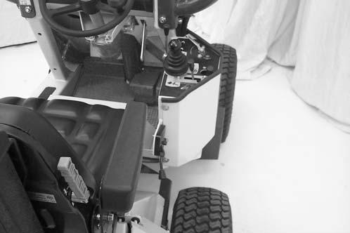
LIFT/TILT CONTROL (Fig. 2)
The lift/tilt control operates the lift arm and tilt cylinders through the loader’s hydraulic control valve. Move the control to the right to tilt the attachment downward; move the control to the left to tilt the attachment up or back. Push the control straight forward to lower the lift arm; pull the control straight back to raise the lift arm. The speed of all movements controlled by the lift/tilt control is directly proportional to the amount of control movement and engine RPM.
1 – Lift/Tilt Control
2 – Differential Lock Control
3 – Pump Control Lever
4 – Auxiliary Hydraulics Control Lever
5 – Telescopic Boom Control Lever
Fig. 2
Telescopic Boom Control
(Fig. 2)
The telescopic boom can be extended when additional boom reach is desirable. Moving the control lever left extends the telescoping boom, and moving the lever to the right retracts it. Extending the boom also reduces the useful load capacity of the loader. Under most operating conditions, the boom should be in the retracted position.
Differential Lock Control
(Fig. 2)
The differential lock control engages and disengages the differential locks. Additional traction is obtained with the lock engaged. Under most operating conditions, the differential locks should be disengaged.
PUMP CONTROL (Fig. 2)
The pump control connects or disconnects one of the two hydraulic pumps, thereby affecting hydraulic speed. One pump is connected when the control is to the right (turtle) and both pumps are connected when the control is to the left (rabbit).
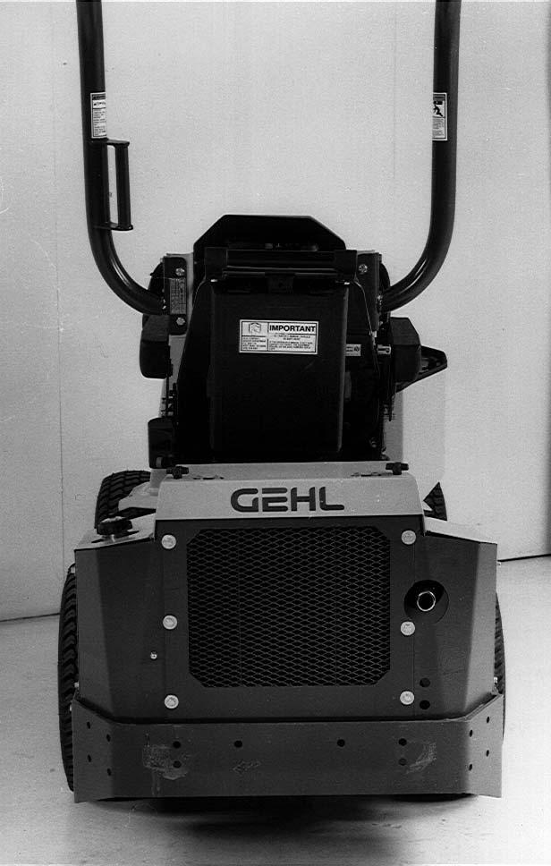
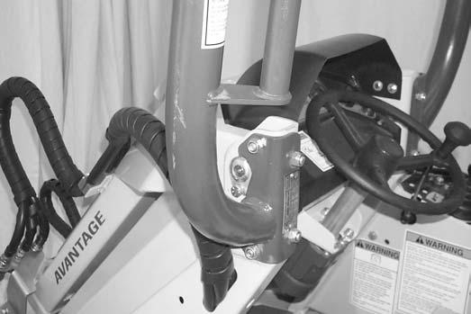
ROLLOVER PROTECTIVE STRUCTURE (ROPS)(Fig. 5)
The rollover protective structure (ROPS) is designed to protect the operator if the loader is accidentally tipped over, provided the operator uses the seat belt. The ROPS is also equipped with a handhold to assist in operator’s compartment entry and exit.
Warning
NEVER operate the loader with the ROPS removed.
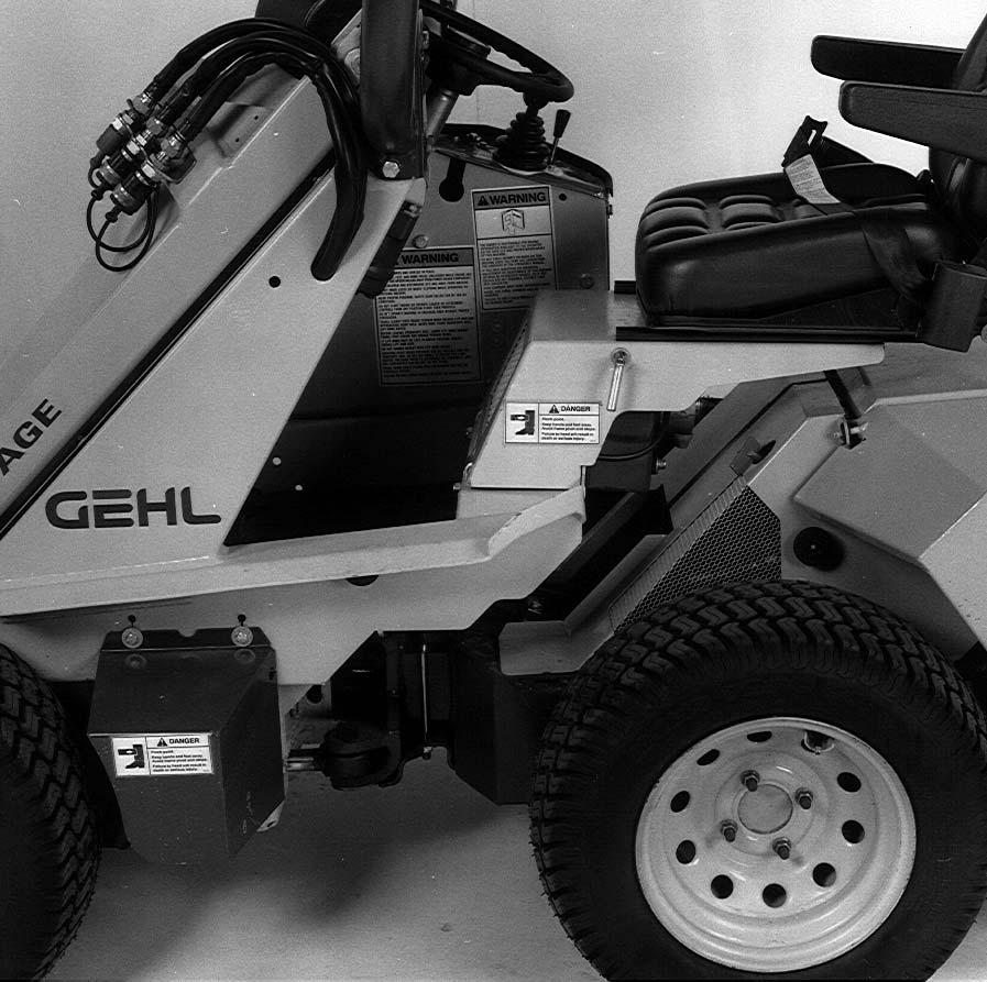
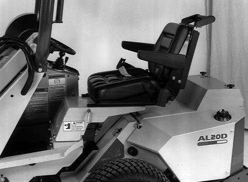
SEAT POSITIONING (See Fig. 3 & 4)
The loader seat is mounted on rails to provide forward or rearward repositioning, to adapt to the operator’s size and comfort. A spring-loaded latch handle is provided for activating the seat adjustment mechanism. Also provided are a seat belt, seat tilt and lumbar adjustments.

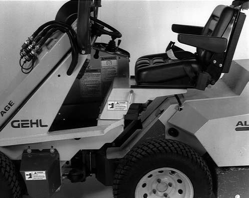
BATTERY SWITCH (See Fig. 4)
A battery ON/OFF switch is located on a panel just above the left rear wheel. The key is removable for security.
An overhead guard is available as optional equipment for use in applications that have overhead hazards.
Warning
DO NOT use this machine in applications with overhead hazards unless an overhead guard is attached to the ROPS.

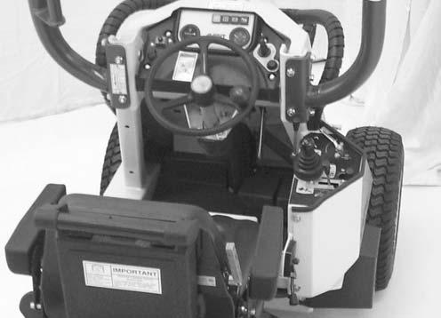
INSTRUMENT & CONTROL PANEL (Fig. 6)
The instrument and control panel contains the following control switches and indicators. International symbols are provided on the panel to represent various functions, conditions and switch positions.
1.Coolant Temperature Gauge – Indicates engine coolant temperature. Under normal operating conditions, this gauge should indicate approximately 185°F (85°C).
4.Hydraulic Fluid Overheat Indicator –Indicates the hydraulic fluid is too hot. Check the hydraulic reservoir to make sure there is adequate fluid and that the hydraulic oil cooler is clean and in working order.
5.Glow Plug Indicator – Indicates when the glow plugs are activated during starting.
6.Hourmeter – Indicates the total operating hours of the loader. The hourmeter is especially useful for logging time in the “Maintenance Schedule” located at the back of this manual.
7.Fuse Block – Two SAE 15 ampere blade-type fuses are provided on the instrument panel to protect the loader electrical circuits.
8.Auxiliary 12 vDC – An auxiliary 12 vDC outlet is provided on the instrument panel.
9.Ignition Switch – The ignition switch controls the starting and stopping of the engine by rotating the switch to various positions. In a clockwise rotation, these positions are:
Off Position - When the key is vertical in the keyswitch, power from the battery is disconnected to the control and instrument panel electrical circuits. This is the only position in which the key can be inserted or removed from the keyswitch.
On (or Run) Position - When the key is turned one position clockwise from the vertical (OFF) position, power from the battery is supplied to all control and instrument panel electrical circuits.

NOTE: All indicators will illuminate as a self-test when the keyswitch is turned to the RUN position with the engine off.
2.Engine Oil Pressure – During normal operation, this indicator should be OFF. If the engine oil pressure drops below a preset value, this indicator will light to warn the operator to IMMEDIATELY stop the engine and determine the cause for the low pressure.
3.Battery – Indicates the condition of the charging system. During normal operation, this indicator should be OFF. If the charge rate is too low, this indicator will light.
Glow Plug Position - When the key is turned clockwise until glow plug light comes on, the glow plugs will be energized for starting the engine. When the glow plug light goes out, you may now continue to start the engine.
Start Position - When the key is turned fully clockwise and held in that position, the electric starter will be energized for starting the engine. Release the key as soon as the engine starts (it will return to the RUN position by itself).
10.Horn Button – Pressing the horn button sounds the horn.
FUEL LEVEL GAUGE (Fig. 4)
The fuel level gauge is located in the fuel cap, on the left rear fender. It indicates the amount of fuel remaining in the 3.2 gallon (12 liter) fuel tank.
ATTACHMENT MOUNTING (Figs. 7 & 8)
Levers are provided for operating the attachment mechanism for mounting and releasing a bucket or other attachment. The latch pins are mechanically linked to the levers and are spring-loaded to ensure positive engagement into the attachment. Raise the lever completely and place it in the rest to disengage the lock pins. Lower the levers to engage the lock pins.
Warning
To prevent attachment release from the lift arms, BE SURE the lock pins are properly secured.
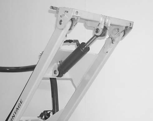
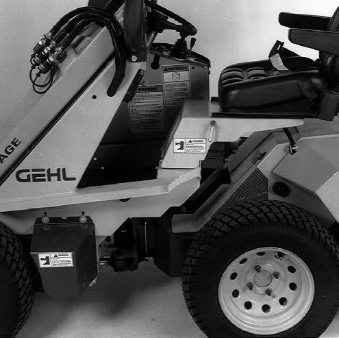
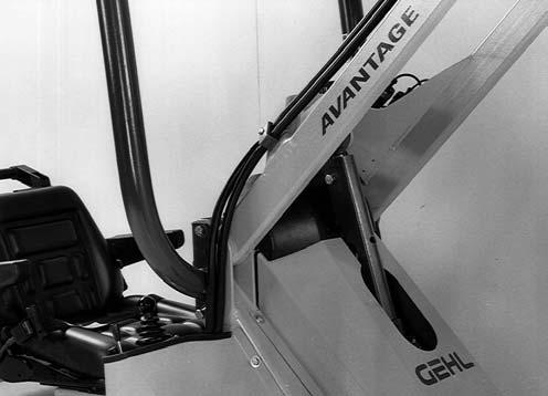
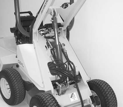
LIFT CYLINDER MECHANICAL LOCK (Figs. 8 & 9)
A mechanical lock is provided for the lift cylinder, and it is to be used as a cylinder block to prevent the raised lift arm from unexpectedly lowering while servicing the loader. BE SURE to engage the lock and secure it with the bolt and nut provided whenever the lift arm is raised for service. When the lock is not being used, secure it to the attachment mount with the bolt and nut provided. The lift cylinder mechanical lock is a safety device. It must be kept in proper operating condition at all times.
Warning
When servicing the loader with the lift arm raised, ALWAYS engage the lift cylinder mechanical lock and the parking brake. Also, turn off the keyswitch, remove the key and take it with you.
Lock Engagement
To engage the lift cylinder mechanical lock, proceed as follows:
1.Lower the lift arm into contact with the loader frame.
2.Shut off the engine.
3.Engage the parking brake.
4.Unfasten seat belt, leave the operator’s seat and remove the bolt and nut that secure the lock to the attachment mount. Return to the operator’s seat with the lock.
5.Restart the engine from the operator’s seat.
6.Move the lift/tilt control to raise the lift arm until the lift cylinder rod is fully extended. Make sure that the lift arm is being held in the raised position by the action of the lift/tilt control. Without leaving the operator’s seat, install the cylinder lock and secure it with the bolt and nut.
7.Shut off the engine again and lower the lift arm until the cylinder lock is engaged.
Warning
BEFORE removing the lift cylinder lock, BE SURE the area BELOW the lift arm and attachment is clear of all personnel and objects.
3.Without leaving the operator’s seat, remove the lock
4.Lower the lift arm.
5.Turn off the engine.
6.Return the lock to its storage location on the attachment mount and secure it with the provided bolt and nut.
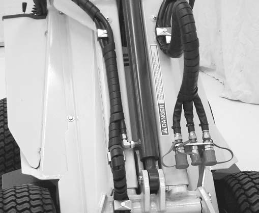
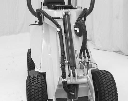
AUXILIARY HYDRAULICS (Figs. 2 & 10)
The loaders are shipped with standard flow auxiliary front hydraulic connections. Three quick-disconnect fittings, conveniently located at the left lift arm, can be used for operating hydraulic attachments. A control next to the lift/tilt control is used to control the oil flow. A notch in the control slot is provided to lock the control for continuous operation. The rate of flow is controlled by the pump control and engine RPM. The two female connections are for bi-directional pressure flow and the male connection serves as a return line to the reservoir (attachment case drain).
Lock Removal WARNING
NEVER attempt to remove the lift cylinder lock by leaving the operator’s seat while the engine is running.
To return the lift cylinder mechanical lock to its “storage” position, proceed as follows:
1.Start the engine from the operator’s seat and raise the lift arm completely.
2.Make sure that the lift arm is being held in the raised position by the action of the lift/tilt control.
IMPORTANT: With the auxiliary hydraulics
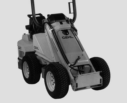
Chapter 6 Operation
General Information
(Fig. 11) CAUTION
BEFORE starting the engine and operating the loader, review ALL safety recommendations in the SAFETY chapter of this manual. Know how to STOP the loader BEFORE starting it. Also, BE SURE to fasten and properly adjust seat belt BEFORE starting engine.
Before Starting Engine
Before starting the engine and running the loader, refer to the Controls & Safety Equipment chapter and familiarize yourself with the various operating controls, indicators and safety devices on the loader.
Starting the Engine WARNING
ALWAYS fasten your seat belt BEFORE starting the loader engine. Leave the parking brake “applied” until the engine is running and you are ready to operate the loader.
The following procedure is recommended for starting the loader engine:
1.Carefully step into the operator’s compartment of the loader while grasping the hand hold.
2.Sit on the seat and fasten the seat belt.
3.Check that all controls are in their “neutral” positions.
4.Check that the battery ON-OFF switch is turned on.
5.Raise the hand throttle to one-fourth of full speed. NOTE: When the key is turned to “ON” position, all monitoring lights will come on.
6.Turn the keyswitch to “ON” position. Advance the keyswitch to glow plug position. After the glow plugs have heated for a sufficient amount of time, the glowplug light will turn off and the engine can now be started. Turn the key to the “START” position to start the engine. The LOW OIL PRESSURE and BATTERY lights should go off.
NOTE: If the engine runs for a short time and stops or will not start, turn the key to the “OFF” position, wait at least two minutes to allow the starter to cool and then repeat step 6.
After the engine starts, allow a sufficient warm-up time before attempting to operate the controls.
Stopping the Loader
The following procedure is the recommended sequence for stopping the loader:
1.Check that your foot is off the directional control pedals.
2.Using the lift/tilt control, lower the lift arm and rest the attachment on the ground.
3.Lower the hand throttle to slowest idle position.
4.Turn the keyswitch key to the “OFF” position to shut off the engine.
5.Apply the parking brake, unlatch the seat belt and grasp the hand hold while climbing out of the operator’s compartment.
Warning
The parking brake MUST BE applied any time the loader is parked on a grade. If the parking brake is not applied, the loader can start to roll because of low resistance in the drive motors due to the oil draining down. Failure to heed could result in death or serious injury.
Loader Movement
The hydrostatic drive of the loader controls forward and reverse direction and speed. As rapidly as the directional control pedal is moved to the “neutral” position, movement of the wheels is slowed accordingly.
Warning
Operate the directional control pedal gradually and smoothly when starting, stopping, turning and reversing loader directions. Excessive speed can be hazardous. ALWAYS exercise caution and good judgement while operating the loader.
First Time Practice Running WARNING
BE SURE the area being used for test-running is clear of spectators and obstructions. For the first time, operate the loader with an empty bucket.
The most smooth and most efficient loader operation is achieved while running the engine at half-throttle. Be sure the engine is warm and then, using your right hand, slowly and smoothly pull straight back on the lift/tilt control to raise the lift arm. Move the control to the left to tilt the bucket back and to the right to tilt the bucket forward. Attempt all raising and lowering functions, and combinations of the two functions before proceeding to operate the directional control pedals.
ALWAYS lower the lift arm and roll the bucket back BEFORE proceeding to operate the directional control pedal.
With your right hand off the lift/tilt control, use your right foot to slowly and smoothly depress the right directional control pedal to travel ahead. Then, slowly and smoothly release the pedal to “neutral” to stop forward movement. To travel rearward, slowly depress the left pedal. Then, slowly release pressure to return the directional control pedal to the “neutral” position to stop reverse movement. Next, turn the steering wheel slowly clockwise to turn right and counterclockwise to turn left. Attempt all forward, reverse and turning movements before proceeding to operate both controls at the same time.
Loader operating skills are only obtained through proper coordination of the loader’s forward and reverse movements, with raising and lowering the lift arm and with tilting the bucket forward and back. To gain proficiency, practice all control operations until you are capable of performing the movements without mistake or hesitation.
Warning
When turning with the loader, BE SURE to maintain adequate side clearance because the operator’s seat extends beyond the turning radius of the wheels.
Warning
BEFORE leaving the operator’s compartment, apply the parking brake and remove the key. Also, BE SURE to lower the lift arm or engage the lift cylinder mechanical lock, as appropriate.
Parking Brake
(See Fig. 11)
Warning
Function and adjustment of the parking brake should be checked regularly to maintain proper operation. NEVER use the parking brake as a means of checking hydrostatic torque, because this will result in parking brake failure.
NOTE: The parking brake is not designed for or intended to be used as the primary means of stopping forward or reverse movement of the loader. The propulsion control foot pedals, when they are returned to their “neutral” positions, provide hydrostatic braking and are the primary means for stopping loader movement.
The proper sequence for correct loader operation is to always apply the parking brake before shutting off the loader engine, and to release the brake only after the engine is running and you are ready to move the directional control pedals.
CHANGING ATTACHMENTS (Fig. 12) WARNING
To prevent unexpected and undesired attachment release from the attachment mount, BE SURE to properly secure the attachment lock pins.
The loader features a quick latching and locking mechanism for mounting an attachment to the front of the lift arm. The mechanism uses two locking pins for attaching and detaching the attachment.
1 – Attachment Lever Locked (1 each side)
2 – Attachment Lock Pin (1 each side)
3 – Front Tie-down Hole Location (1 each side)
4 – Attachment Lever Unlocked Position
Fig. 12
Attaching
1.Raise the lock pins and place their handles in the unlocked position to fully retract the lock pins.
2.Start the loader engine and make sure the lift arm is lowered and in contact with the loader frame.
3.Align the loader squarely with the back of the attachment.
4.Tilt the attachment mechanism forward until the mating parts of the mechanism are in line with and slightly below the hooks on the back of the attachment.
5.Slowly drive the loader forward and, at the same time, roll the attachment mechanism back to engage the hooks on the attachment.
6.Stop forward travel when the hooks are engaged but, continue to roll the attachment mechanism back to pick the attachment up off the ground. When the attachment mechanism is rolled back completely, exercise the MANDATORY SAFETY SHUTDOWN PROCEDURE (page 8)
7.With the loader engine OFF, leave the operator’s compartment, and lower the lock pins to secure the attachment.
Detaching
1.Roll the attachment mechanism back as far as it will go. Once the mechanism is rolled all the way back, exercise the MANDATORY SAFETY SHUTDOWN PROCEDURE (page 8)
2.With the loader engine OFF, leave the operator’s compartment, and raise the lock pins and place their handles in the unlocked position to fully retract the lock pins.
3.Start the loader engine and make sure that the lift arm is lowered and in contact with the loader frame.
4.Tilt the attachment mechanism forward and slowly back the loader until the attachment is free from the loader.
Moving Materials With A Bucket
Material Densities
The following table lists densities for some common materials that could be carried in a bucket. The densities listed are average values and intended only as a guide for bucket selection. For a material that is NOT in the table, obtain its density value before selecting the appropriate bucket.
NOTE: The rated operating load (SAE) of the loader is one-half of the tipping load. To prevent exceeding the operating capacity of the loader, use the table of common material densities and loader tipping load chart to determine the proper size bucket to use, based on the type of material to be carried.
To use the table, find the material name and see what its maximum density is. Then, divide the operating capacity of the loader (one-half the tipping load) by the material density to determine the maximum size bucket to use for a heaped load.
NOTE: Where the material density is listed as a range (clay at 80-100 pounds per cubic foot, for example), always use the maximum density (100 lbs/ cu-ft in this example) for making calculations. (Also, see the following examples.)
EXAMPLE 1: If wet sand (density of 125 lbs/cu. ft.) is to be hauled, the maximum bucket size is (800 lbs divided by 125 lbs/cu. ft. = 6.4 cu. ft.). Therefore, you could safely use a 5 cu. ft. bucket.
EXAMPLE 2: If earth-wet loam (density of 65 lbs/cu. ft.) is to be hauled, the maximum bucket size is (800 lbs divided by 65 lbs/cu. ft. = 12.3 cu. ft.). Therefore, you could safely use a 8.5 or 8.75 cu. ft. bucket.
NOTE: Light material buckets are to be used ONLY for moving snow or materials of similar densities.
The Specifications chapter lists the available buckets and their capacities to help you determine which size bucket to use. You can always use a smaller capacity bucket, but not a bucket with greater capacity than the calculated maximum unless it is only partially filled.
Warning
NEVER use the loader to move in excess of one-half of the rated tipping load of the loader as shown on the tipping load charts. Tipping loads decrease if the loader is turning. Tipping loads also decrease if the optional telescoping boom is extended.
Loader Operation Warning
ALWAYS maintain a safe distance from electric power lines and avoid contact with any electrically charged conductor or gas line! Accidental contact or rupture can result in electrocution or an explosion! Contact the “Digger’s Hotline” or proper local authorities for utility line locations BEFORE starting to dig!
NOTE: The loader’s working ability is increased when ground speed is decreased. To obtain maximum tractive effort while filling the bucket, depress the propulsion control foot pedal only a slight amount from its “neutral” position.
Digging with and Loading a Bucket (Figs. 13 through 16)
To dig with and load a bucket, first lower the lift arm into contact with the loader frame and then tilt the bucket’s cutting edge down into contact with the ground. Move the loader into the material and, as engine loads, tilt the bucket back slowly and, at same time, gradually ease pressure on the propulsion foot pedal to decrease travel speed while maintaining tractive effort.
Hard-packed Materials
When attempting to fill the bucket while working with most hard-packed materials, it will usually be necessary to raise the lift arm while rolling the bucket back. Also, avoid driving onto the material to be picked up, if at all possible.
Warning
ALWAYS carry loaded bucket or fork with lift arm resting on loader frame. For additional stability when operating on inclines, ALWAYS travel with heavier end of loader toward the top of the incline.
With the bucket filled, back the loader away from the material and rest the lift arm against the loader frame before proceeding to the dumping area.
Dumping the Load Onto a Pile
Carry loaded bucket as low as possible until reaching the pile. Slowly stop forward motion and raise the lift arm high enough so that the bucket clears the top of the pile. Then, slowly move the loader ahead to position the bucket to dump the material on top of the pile. Empty the bucket and back the loader away while lowering the lift arm and rolling the bucket back.
Dumping the Load Into a Box
Carry the loaded bucket (or fork) low and approach the truck, trailer or spreader box squarely with the side of the box. Stop your approach as close to the side of the box as possible while still allowing clearance for raising the lift arm and loaded bucket (or fork). Then, raise the lift arm until the bucket clears the top of the box and slowly move the loader ahead to position the bucket (or fork) over the inside of the box. After the material is dumped, slowly back away from the box and lower the lift arm while rolling back the bucket (or fork).
Dumping the Load Over a Solid Embankment WARNING
Do NOT drive too close to an excavation or ditch; BE SURE the surrounding ground has adequate strength to support the weight of the loader and the load.
Carry the loaded bucket (or fork) as low as possible while slowly traveling toward the dumping area. Stop the loader at the position where the bucket extends half-way over the edge of the embankment. Then, tilt the bucket (or fork) forward and raise the lift arm to dump the material. After the material is dumped, back away from the embankment slowly while lowering the lift arm and rolling back the bucket (or fork).
Scraping with a Bucket (Figs. 17 & 18)
For scraping, the loader should be operated in the forward direction. First, position the lift arm down against the loader frame. Tip the bucket cutting edge at a slight angle to the surface being scraped. While traveling slowly forward, with the bucket in this position, material can flow over the cutting edge and collect inside the bucket.
Leveling with a Bucket (Fig. 19)
First drive the loader to the outer edge of the area to be leveled. Then, with the lift arm down against the frame, tilt the bucket forward to place the bucket cutting edge at a 30 to 45 degree angle to the surface being leveled. Proceed to drive the loader rearward, dragging the dirt and, at the same time, leveling it.
Warning
For additional stability when loading the loader on a trailer, ALWAYS travel with heavier end of loader toward the top of the incline.
Fig. 19: Leveling with a Bucket
Using Pallet Forks
If possible, plan to load, unload and turn on flat, level ground. Inspect the load to be moved. If it appears to be unstable, do not attempt to move it.
Approach the load slowly and squarely with fork tips level. Move slowly forward to engage the load. Position the load equally on both forks. Continue forward until the load touches the fork backrest. Roll the forks back to position the load for travel. Carry the load low. DO NOT make any abrupt movements.
BE SURE the landing point can safely support the load. Move forward slowly into the unloading position. Lower the load onto the landing point. Tilt the forks forward to be horizontal, and then back away carefully to disengage the forks.
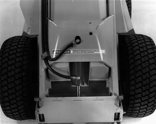
TOWING & HIGHWAY TRAVEL
When it becomes necessary to move the loader over long distances, obtain and use a Avantage Tool System Trailer or an Gehl LT8500 Loader Trailer. When transporting the loader, ALWAYS install the steering frame lock, securing it with the provided lock pin.
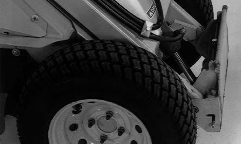
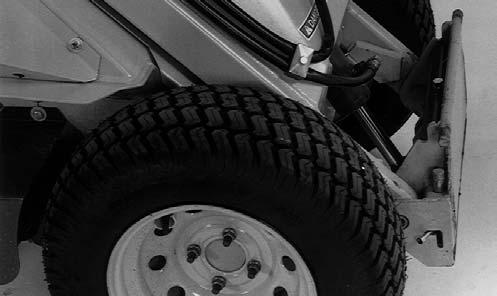
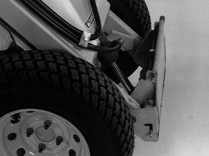
TIE-DOWN LOCATIONS (Figs. 21 and 12)
Chapter 7 Adjustments Warning
BEFORE adjusting this unit, exercise the MANDATORY SAFETY SHUTDOWN PROCEDURE (page 8).
Engine
Loaders are provided with separate engine maintenance manuals which should be consulted for engine-related specifications, adjustments, maintenance and service information.
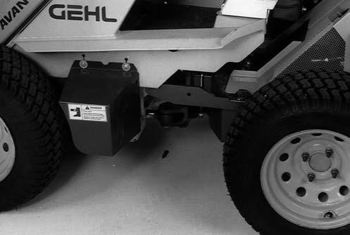
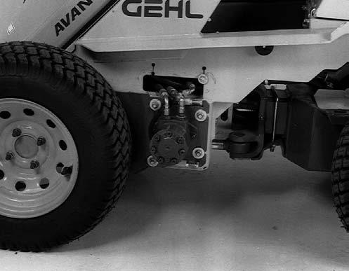
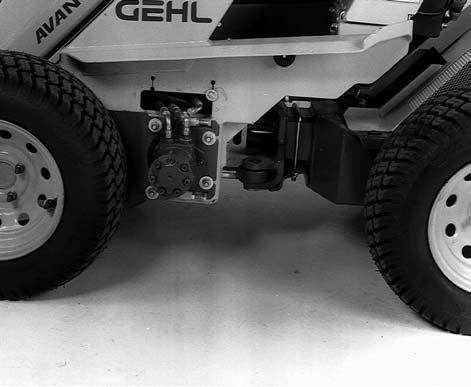
Drive Chains
Each wheel is driven by a hydraulic motor coupled with a drive chain. To adjust drive chain tension, loosen the four motor mounting bolts and move the motor with the two adjusment bolts and lock nuts. The chains should be adjusted to have 1/4″ (6 mm) or less of slack with 10 lbs (45 N) of force, but should not be adjusted so the chain is tight.
Chapter 8 Lubrication
General Information Warning
NEVER lubricate this unit when any part of the machine is in motion. ALWAYS BE SURE to exercise the MANDATORY SAFETY SHUTDOWN PROCEDURE (page 8) BEFORE lubricating this equipment.
It is important to apply sufficient oil and grease to prevent excessive part wear and early failure.
IMPORTANT: Whenever service is performed on hydraulic components (valves, cylinders, hoses, etc.) or transmissions, care must be taken to prevent discharging fluid onto the ground. Catch and dispose of fluid per local waste disposal regulations.
Engine Lubrication
All engine maintenance and lubrication requirements are listed in the Engine Operator’s Manual that is supplied with each loader.
Drive Chains
Lubricate all drive chains every eight hours of operation using a good grade of foaming aerosol lubricant such as NAPA Chain and Cable Lubricant. This type of lubricant increases the life of the chain three to four times over those lubricated at eight hour intervals with new motor oil. The recommended method is to spray the entire length of chain on the center of the rollers. It is more effective to oil chains after use, while they are still warm.
IMPORTANT: To minimize wear on the sprockets, the chains should be replaced after they become worn and are 3% longer than their original length, or when the tightener (where provided) has reached the end of its adjustment.
Hydraulic Reservoir
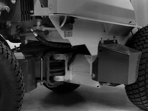
The loader is equipped with an 8 gallon (30 L) hydraulic revervoir. The loader is provided with a dipstick on the hydraulic reservoir cap. Markings on the dipstick represent both full and low (add oil) levels. The resevoir is accessed by raising the lift arms and removing the front Cover. Use hydraulic oil with anti-wear, anti-foam and anti-oxidation additives that conforms to ISO Viscosity Grade 46, such asMobil DTE 15M, Amoco Rykon 46, or BP Energol HLP-HD 46. Use of synthetic hydraulic fluids is not permitted. The hydraulic oil should be changed every 500 hours (or annually).
IMPORTANT: BE SURE to install the lift arm lock when accessing the hydraulic reservoir.
Greasing
IMPORTANT: Grease all fittings at intervals of operation listed, after pressure washing, and before and after storing unit. Use a good grade of lithium-base grease.
Wipe dirt from the fittings before greasing to prevent dirt from being forced into the bearing or pivot. Replace any missing fittings. Force grease into the fitting until it comes out at the bearing seal or the shaft. To minimize dirt build-up, avoid excessive greasing.
IMPORTANT: In addition to the grease fittings, repack the wheel bearings at least annually.
Grease Fitting Locations
Grease Every 10 Hours (or Daily)
1.Lift Arm Pivots (2 places)
2.Lift Arm Cylinder Pivots (2 places)
3.Attachment Mount Pivots (2 places)
4.Attachment Mount Cylinder Pivots (2 places)
5.Articulation Joint (2 places)
6.Articulation Joint Cylinder (2 places)
7.Optional Telescoping Boom Cylinder Pivots (2 places)
8.Optional Telescoping Boom Slides (2 places)