10 minute read
SAFETY SIGNS

from Frontier Rotary Tillers RT1142 RT 1157 RT 1265 RT 1149 RT 1165 Operator's Manual(MHF07010181) - PDF

Safety-alert symbol
Read and recognize safety information.
Be alert to the potential for personal injury when you see this safety-alert symbol.
On your machine safety labels, the words DANGER, WARNING, and CAUTION are used with safety-alert symbol.
DANGER identifies the most serious hazards. In this manual, the word CAUTION and this symbol call attention to safety messages.
Identification machine
Identification plate machine
Machine safety labels
1) WARNING: AVOID INJURY FROM ROTATING KNIVES:
• Keep hands, feet and clothing away.
2) WARNING: AVOID INJURY FROM PTO:
• Keep all shields in place. Keep hands, feet and clothing away.
• Operate only with 540 RPM.
3) CAUTION: AVOID INJURY
• Read Operator’s Manual
• Ballast power unit per operator’s manual
• Know location and function of controls
• Keep all shields in place
• Stay clear of power driven parts
• Never carry riders
• Keep people and pets a safe distance away from machine BEFORE DISMOUNTING OR SERVICING
• Shut off engine and remove key
• Lock brake for park
• Lower or block up machine
4) DANGER: ROTATING DRIVELINE - CONTACT CAN CAUSE DEATH - KEEP AWAY! - DO NOT OPERATE WITHOUT:
• All driveline, tractor and equipment shields in place
• Drivelines securely attached at b oth ends
• Drivelines shields that turn freely on driveline.
5) DANGER: SHIELD MISSING DO NOT OPERATE Picture Note: Separate telescoping driveshaft members to locate safety label. Label attached to outer profile tube.
Safety Signs - Page 7
Machine Safety Labels And Positions
Machine Safety Labels And Positions

Preparing The Vehicle
Preparing the tractor
CAUTION: Avoid injury. Proper ballastings is required for safe operation of your tiller
IMPORTANT: Refer to the tractor operator manual for proper ballasting information and tire in flation
• A 540 rpm PTO
• Refer to the tractor operator is manual for correct ballasting and tire pressure, depending on installed equipment.
Park vehicle safety
• Stop vehicle on a lever surface, not on a slope.
• Disengage PTO.
• Engage the park brake.
• STOP the engine.
• Remove the key.
• Before you leave the operator’s seat, wait for engine and all moving parts to STOP.
Stay clear of rotating drivelines
Entanglement in rotating driveline can cause serious injury or death:
• Wear close fitting clothing.
• STOP the engine and be sure PTO driveline is stopped before gett ing near it.
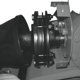
Installing tiller on tactor
1. Back tractor into position and align draft links (A) with draft link brackets on tiller using tractor rockshaft control.
CAUTION: Before you work around hitch:
• STOP engine.
• LOCK park brake.
• FIRMLY block tiller on horizontal surface.
Locate driller pin in holes (B). RT 1142-1149 model.
2. Fasten each draft link to draft link brackets with drilled pins and quiklock pins (C).
Preparing the vehicle - Page 10
Locate driller pin in lower lift brackets holes (B). RT 1157-1165 model.
2. Fasten each draft link to draft link brackets with drilled pins and quiklock pins (C).
Locate driller pin in holes (B). RT 1265 model.
2. Fasten each draft link to draft link brackets with drilled pins and quiklock pins (C).
Locate driller pin in top holes (D) RT 1142-1149 model.
3. Install center link (F) on tiller and fasten with drilled pin and quiklock pin (E).
Locate driller pin in top holes (D) RT 1157-1165 and 1265 model.
3. Install center link (F) on tiller and fasten with drilled pin and quiklock pin (E).
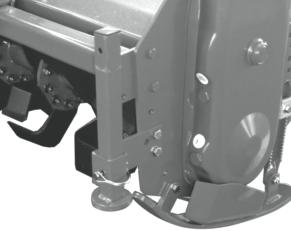
4. Install PTO shaft to tractor.
IMPORTANT: Tiller MUST BE level front to rear.
• Engage the cardan shaft and check that it is perfectly locked on the tractor PTO (G). Check that the guard (H) is free to turn and fix it with the relative latch.
5. Raise tiller.
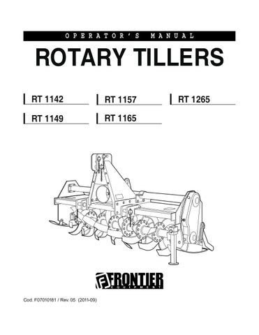
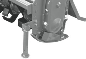
6. Remove spring locking pin (K) from parking stand.
7. Slide parking stand (I) all the way up on tiller bracket (J).
8. Fasten with spring locking pin (K).
9. Level tiller (See Leveling Tiller in the Operating Tiller section).
10. Adjust sway chains on tractor lower draft arms to minimize side way.
PTO shaft
The PTO shaft, supplied with the machine, is of standard length.
Therefore it mi ght be necessary to adapt the PTO shaft. In that case, before doing anything, consult the Manufacturer for the eventual adaptation.
When the PTO shaft is fully extended, the two tubes must overlap by at least 15 cm (A). When fully inserted, the minimum play must be 4 cm (B).
CAUTION: If the implement is used on another tractor, always check the that the guards completely cover the rotating parts of the PTO shaft.
Installing - Page 12
PTO shaft with shear pin (1142 model)
The shear pin, inserted in the PTO shaft, is equipped with a safety bolt (A) that is set for an average force. Whenever unduly resistant obstacles cause the bolt to shear, it must be replaced by a new bolt.
PTO shaft with clutch (1149-1157-1165-1265 model)
The PTO shaft can be equipped with safety clutch to protect the transmission components of the machine from stress and/or excessive overloads.
The tilt of the PTO shaft must not exceed 10 degrees.
The clutch is already pre-adjusted for average stress. If it slips too easily (and overheats), it will be necessary to evenly tighten all the nuts (D) that retain the spring. The clutch disks must be changed if the clutch still slips after all the nuts have been tightened. If the clutch does not slip, evenly unscrew all the spring fixing nuts (D). Unscrew one turn at a time and check the clutch after having worked about 300 meters. Repeat the operation if necessary, remembering to unscrew one turn at a time. If the clutch maintains a temperature of about 40-50°C (104-122°F) degrees during work, this means that it has been correctly regulated.
IMPORTANT: Never fully tighten the nuts. This would void the function of the springs and, subsequently, of the clutch, thus damaging the transmission components.
NOTE: This inspection must be performed at the beginning of each new season.
Quick Coupler (optional)
1) Install hitch Quick Coupler (A) on the tractor (see tractor operator manual).

2) Stop vehicle on a level surface, not on a slope, then move the tractor back until the Quick Coupler (A) is range with the (B) and (C) hitch points.
3) Raise the Quick Coupler (A) and make sure that tiller’s hitch is in the right position (E).
CAUTION: Before you work around hitch:
• STOP engine.
• LOCK park brake.
• FIRMLY block tiller on horizontal surface. .
Park vehicle safely
• Stop vehicle on a level surface, not on a slope.
• Disengage PTO.
• Engage the park brake.
• STOP the engine.
• Remove the key.
• Before you leave the operator’s seat, wait for engine and all moving parts to STOP.
Stay clear of rotating drivelines
Entanglement in rotating driveline can cause serious injury or death:
• Wear close fitting clothing.
• STOP the engine and be sure PTO driveline is stopped be fore gett ing near it.
Installing - Page 14
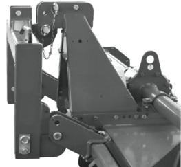
Removing tiller
1. Raise tiller.
2. Put parking stand (A) in the DOWN position: Install spring locking pin (C) in order to secure parking stand (A) to the tiller bracket (B).
3. Lower tiller to the ground.
CAUTION: Before you work around hitch:
• STOP engine.
• LOCK park brake.
• FIRMLY block tiller on horizontal surface.
4. Disconnect driveline from tractor by pulling back on coupler to release it from the LOCKED position.
5. Remove quik-lock pin (D) and drilled pin (E) from center link (F).
NOTE: Put quik-lock pins and driller pins back into brackets on tiller for storage.
6. Remove draft links (J) from draft link brackets (G) by removing quiklock pins (H) and drilled pins (I).
NOTE: Put quik-lock pins and driller pins back into brackets on tiller for storage.
7. Drive tractor forward slowly.
Removing tiller with Quick Coupler
1. Raise tiller.
2. Put parking stand (A) in the DOWN position: Install spring locking pin (C) in order to secure parking stand (A) to the tiller bracket (B).
3. Lower tiller to the ground.
4. Raise the two Quick Coupler levers (D) to unlock tiller (Quick Coupler figure, page 14).
5. Lower Quick Coupler until free from the tiller.
Operate safely
• Protect your hands when you inspect or unplug the tiller. You may need gloves or tools, such as a screwdriver or scraper. Be sure hardware is tight. Repair or replace damaged, badly worn, or missing parts. Be sure guards and shields are in good condition and fastened in place. Make any necessary adjustments before you operate.
• Clear work area of objects that you do not want tilled into the ground or that might damage the tiller. Consider the tilling area and set up a safe tilling pattern. Do not till under condition in which traction or stability is doubtful. Keep people and pets out of the work area. Stop machine if anyone enters the area.
• If you hit an object, stop the machine and inspect it. Make repairs before you operate. Keep machine properly maintained and in good working order.
• DO NOT leave machine unattended when it is running.
• Only operate during daylight or with good arti ficial light.
• DO NOT let anyone, ESPECIALLY CHILDREN, ride on machine or vehicle. Riders are subject to injury such as being thrown off. Riders may also obstruct the operator’s view, resulting in the machine being operated in an unsafe manner.
• DO NOT let children or an untrained person operate machine.
• DO NOT wear radio or music headphones while operating the machine. Safe operation requires your full attention.
It is absolutely forbidden to stand between the tractor and the implement when maneuvering the lift control from the outside.
Operating - Page 16
Operating
Wear appropriate clothing
• Wear close fitting clothing and safely equipment appropriate for the job.
• Loud noise can cause impairment or loss of hearing, wear a suitable protective device such as earplugs.
Stay clear of rotating drivelines
Entanglement in rotating driveline can cause serious injury or death:
• Wear close fitting clothing
• Stop the engine and be sure PTO drivelines is stopped before gett ing near it.
CAUTION: Before you work around hitch:
• STOP engine.
• LOCK park brake.
• FIRMLY block tiller on horizontal surface.
Raising parking stand
1. Remove spring locking pin (C).
2. Slide parking stand (A) all the way up on tiller bracket (B).
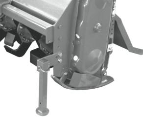

3. Fasten with spring locking pin (C).
Lowering parking stand
1. Remove spring locking pin (C).
2. Slide parking stand (A) and put down on tiller bracket (B).
3. Install spring locking pin in order to secure parking stand to the tiller bracket.
4. Fasten with spring locking pin (C).
Leveling attachments (side-to-side)
1. Start the engine. Raise the tiller.
2. Stop the engine. Lock the park brake.
CAUTION: DO NOT work under a raised tiller unless it is safely supported.
Leveling tiller (front-to-rear)
1. Start the engine.
2. Lower the tiller to 25 mm (1 in.) off the ground.
3. Stop the engine.
4. Make sure the top of the tiller is LEVEL, or PARALLEL with the ground, front-to-rear.
5. Adjust level, if necessary. To adjust level: a. Start the engine. b. Lower the tiller to the ground. c. Stop the engine. d. Loosen jam nut (A). e. Tighten jam nut.
• Shorten the center link (B) to lower the front of the tiller.
• Lengthen the center link (B) to raise the front of the tiller.
CAUTION: Before you work around hitch:
• STOP engine.
• LOCK park brake.
• FIRMLY block tiller on horizontal surface.
Adjusting skid shoes
Before adjusting skid shoes lift tiller, place tiller on top of two wooden blocks underneath tiller rotor (see figure).
1. Raise tiller.
2. Place wooden blocks.
3. Lower tiller on wooden blocks.
4. Loosen pivot bolt (A) and (D).
5. Loosen adjusting bolt (B) and lock nut.
6. Adjust skid shoe (C) to desired position.
7. Tighten bolts (A), (B) and (D).
NOTE: Adjust both skid shoes to same depth.
6. Repeat above steps for the other skid shoe.
Adjusting leveling board
1. Install chain (A) in bracket (B).
2. Lower leveling board to top of ground (C):
• Tilled soil (D) will be fine and level.
• Tractor speed will determine size of clods (E).
3. Raise leveling board (C):
• Tilled soil (D) will be coarse and rough.
• Tractor speed will determine size of clods (E).
CAUTION: Before you work around hitch:
• STOP engine.
• LOCK park brake.
• FIRMLY block tiller on horizontal surface.
Adjustable offset
The tiller unit can be shifted sideways in relation to the three-point hitch. This makes the implement extremely versatile during the various working conditions. Use of the hexagonal drive shaft allows the tiller unit to quickly slide, thus notably simplifyng the operation. The following operations must be carried out:

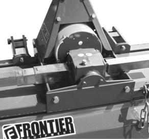
RT 1142 - 1149
1. Thorougly clean the frame and relative guides to allow the parts to work smoothly.
2. Loosen the bolts (A) that fix the bracket and leave these free.
3. Move the carriage to the position required and the tighten the two carriage fixing bolts.
RT 1157 - 1165
1. Thorougly clean the frame and relative guides to allow the parts to work smoothly.
2. Loosen the bolts (B) that fix the bracket and leave these free.
3. Move the carriage to the position required and the tighten the two carriage fixing bolts.
Operating
Tilling tips
Before You till:
• Pick up rocks and foreign objects.
• Mow tall weeds and grass to keep them from wrapping around tines or tine shaft.
• Check tines. Loose, bent, broken, or missing tines reduce operating efficiency. If necessary, replace tines.
Test the soil by squeezing it in your hand. If soil forms a ball, it is too wet to till. If soil does not compress easily or falls apart, it is ready to till.
DO NOT till when soil is wet. Wet soil will stick to the tines and tine shaft. Wet soil will also dry out and become hard, making it hard to work with during the grow ing season.
During tilling
CAUTION: Never lower tiller into the ground while the tractor is turning
• DO NOT back up or make sharp turn with tiller in ground.
• Move PTO switch lever to ON when tiller is out of the ground. Move tractor forward and lower tiller into the ground.
• When you till hard ground or sod, till at a shallow depth on first pass. Increase depth on each pass.
• When tilling on a hillside:
- Work up the the slope, if possible.
- If lateral work cannot be avoided, work from the top to the bottom in order to limit any terracing effect.
Replacement parts
See Service Dealer for original parts.
PART NUMBERS MAY CHANGE, use part numbers listed at the end of this manual when you order. If a number changes, your dealer will have the latest number.
WHEN YOU ORDER PARTS, your Frontier Equipment dealer needs your machine serial number. This is the number you have recorded in the INTRODUCTION section in the front of this manual.
Operating - Page 20