4 minute read
SERVICE MACHINE SAFELY

from Frontier Rotary Tillers RT1142 RT 1157 RT 1265 RT 1149 RT 1165M Operator's Manual(5MHF07010181)

Practice safe maintenance
• Understand service procedure before doing work. Keep area clean and dry.
• Never lubricate, service, or adjust machine while it is moving. Keep safety devices in place and in working condition. Keep hardware tight.
• To prevent from gett ing caught, keep hands, feet, clothing, jewelry, and long hair away from any moving parts.
• Before servicing machine, lower it to the ground. Disengage all power and stop the vehicle engine. Lock vehicle park brake and remove the key.
• Securely support any machine elements that must be raised for maintenance.
• Keep all parts in good condition and properly installed. Fix damage immediately. Replace worn or broken parts. Remove any buildup of grease, oil, or debris.
• Unauthorized modifications to the machine may impair its function and safety.
Wear appropriate clothing
• Wear close fitting clothing and safety equipment appropriate for the job.
• Loud noise can cause impairment or loss of hearing, wear a suitable protective device such as earplugs.
• Do not wear radio or music headphones while servicing the machine. Safe servicing requires your full attention.
Stay clear of rotating drivelines
Entanglement in rotating driveline can cause serious injury or death:
• Stop the engine and be sure PTO drivelines is stopped before gett ing near it.
Service Machine Sa fely - Page 21
Service lubrication
WARNING: • Firmly block tiller on horizontal surface.
• Always keep oils and greases well away from children’s reach.
• Always thoroughly read the warnings and precautions indicated on the containers. Avoid contact with the skin.
• Always thoroughly and fully wash after use. The utilized oils should be treated in compliance with the current anti-pollution laws.
Every 8 work hours
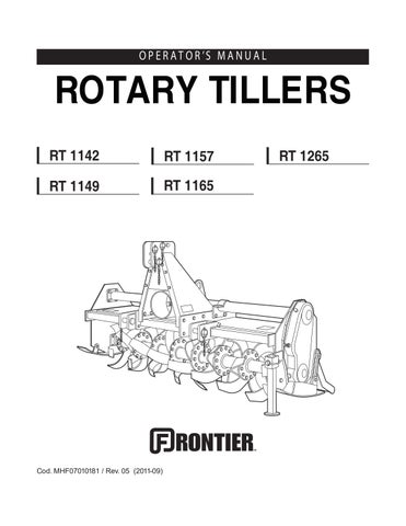
• Grease the cardan shaft cross journals (A) and (B).
• Check that the bolts fixing the hoe blades (M) are well tightened.
• Grease the rotor spindles (D).
Every 50 work hours (see page 23 for E, F, G, I and H)
• Check the level of the oil in the gearbox or in the reduction unit (E) and top off to the level mark on the rod as necessary.
• Transmission chain : check the level of the oil in the side casing of the transmission unit, unscrew the level plug (G) and check that oil flows out. Add oil through the fill plug (F) if necessary. It should flow from the level plug (G).
Every 400 work hours
• Change the oil in the reduction unit and transmission casing by completely draining off the old oil through the drain plug under the reduction unit and through the transmission drain plug.
• When this operation is carried out, it is also advisable to demount and clean the clutch disks (C) (if the cardan shaft has a clutch). Check the tightening of the clutch springs.
Every 1000 work hours
Greasing chain (RT 1142 - 1149)
1. Install park stand.
2. Lower tiller to the ground.
3. Remove all bolts and nuts (A).
4. Remove cover (B).
5. Put a heavy coat of moly high temperature extreme pressure grease GR MU EP2 or an equivalent on chain and sprockets.
6. Install cover.
7. Install and tighten nuts.
Greasing and lubricant points
RT 1142 - 1149 model
D) Rotor spindle lubricator
E) Reduction unit oil plug: Qty. 0.5 lt (0.13 US gal.)
M) Hoe blades fixing bolts
N) Greasing chain (see Service lubrication: Every 1000 working hours): Qty. 0.5 Kg (1.1 lb)
Greasing and lubricant points
RT 1157 - 1165 and 1265 model
D) Rotor spindle lubricator
E) Reduction unit oil plug
F) Transmission oil fill plug
G) Transmission oil drain plug
M) Hoe blades fixing bolts
Lubricants
• It is advisable to use SAE 85W/140 OIL or equivalent for the reduction unit (or gear box) and side transmission.
• It is advisable to use GR MU EP 2 GREASE or equivalent for all greasing points.
Service
Chain stretcher
RT 1142-1149 and RT 1157-1165 model
Automatic chain s tretcher re gulates the tension of the drive chain.
RT 1265 model
A special mechanical chain s tretcher re gulates the tension of the drive chain (A). If there is too much play, then you must loosen lock nut (B) and tighten screw (C) as much as necessary.
Then tighten lock nut which locks the adjustment screw into place.
Service intervals
Every 50 working hours:
• Tighten mast brackets bolts.
• Tighten skid shoe bolts.
B C A
Bolts tightening torques - settings given in Nm (lb-ft)
Replacing tines
CAUTION: To prevent injury: Wear heavy gloves when replacing tines.
To get the best performance from your tiller:
• Replace badly bent, worn, or broken tines immediatly.
• Replace worn or broken hardware (see your Frontier dealer for correct hardware).
• MAKE SURE to replace tines on ONE spindle at time to keep spiral tine pattern.
• Tine cutting edge MUST BE facing forward in direction of tine rotation.
Service - Page 24
CAUTION: Make sure you block tiller before doing any service on the tiller.
• STOP engine.
• LOCK park brake.
• FIRMLY block tiller on horizontal surface.
Tines can be changed with the tiller mounted on tractor. Make sure you block the tiller before doing any service on the tiller.
Tines
Before replacing tines make sure the tiller is firmly blocked.
The tines with which the rotary tiller is equipped can work soils of normal conformation. Check the degree of wear and condition of the tines each day. If the blades should accidentally bend (or break) during work, they must be immediately replaced.
First - Identify tines:
Remember to mount the new tine in exactly the same position as the old one (A). If several tines must be replaced, it is advisable to remove and assemble one tine at a time in order to prevent positioning er rors. The tillers are normally equipped with 4 blades per flange.
Second - Install New Tines:
1. Raise tiller with a safe lifting device.
1. Put safety stands or blocks under tiller.
3. Stand facing rear of tiller and study placement of tines.
4. Remove four bolts, lock washers, and nuts (C).
NOTE: Make sure to replace tines on ONE spindle at a time to keep spiral tine pattern.
5. Remove left-hand tine (A) and right-hand tine (B).
6. Install new tines and fasten with bolts, lock was hers, and nuts (removed above).
NOTE: Two bolts go in from each side. Refer to sketch at right.
7. Tighten bolts.
CAUTION: The heads of the bolts fixing the hoe blades in place must be on the side of the hoe blades themselves, while the nut with relative washer must be on the flange side (B). Tighten bolts to 91 Nm (67 lb-ft).