7 minute read
Adjustable Slider Mounting Bracket & Draper


Position #1
This is suggested for use with corn heads and draper heads. Notice the Slider-Base Assembly points toward the left side of the transporter. The head will rest against the top slider assembly bracket and on the top rail of the header transport. Adjust the brackets according to dimension “A” and the reference chart provided below.
Position #1 has the brackets shown in the lowered position, which allows the transporter to be utilized for older models of heads and combines. Locate heads so the stalk rollers are to the left of the top rail and there is clearance between the left tire and drive shafts.
edo Me pyET E F. mi "DA"
D J3 9 6d Hea orn C) 54"(137cm
D J3 9 8d Hea orn C) 54"(137cm
D J3 29 1d Hea orn C) 54"(137cm
D J4 9 8d Hea orn C) 56"(142cm
D J3 4 6d Hea orn C) 52"(132cm
D J3 4 8d Hea orn C) 52"(132cm
D JC 06 6d Hea orn C) 54"(137cm
D JC 08 6d Hea orn C) 54"(137cm
D JC 12 6d Hea orn C) 54"(137cm
D JC 16 6d Hea orn C) 54"(137cm
D JC 18 6d Hea orn C) 54"(137cm
Position #2
This is suggested for use with platform type heads. Notice the Slider-Base Assembly points toward the right side of the transporter. The head will rest against the top slider assembly bracket and on the top rail of the header transport. Adjust the brackets according to dimension “B” and the reference chart provided below.
Position #2 has the brackets shown in the raised position. This is illustrated by dimension “C”. The brackets are pinned 2 in (5 cm) higher to prevent floating arms on the bottom of platforms from resting on the frame of the transport. This also allows corn head to be raised up and create more clearance between PTO shafts and transport tires. Locate skid shoes so they rest on the top rail.
dnar Bl edo Me pyETE F. mi "DA"
D JD 36 9r rape D) 56"(142cm
D JD 25 6r rape D) 56"(142cm
D JD 30 6r rape D) 56"(142cm
D JD 35 6r rape D) 56"(142cm
D JD 40 6r rape D) 56"(142cm
D JD 35F 6r rape D) 50"(127cm
D JD 40F 6r rape D) 50"(127cm dnar Bl edo Me pyETE F. mi"DB "
D J0 2 9m latfor P) 36"(91cm
D JF 25 6m latfor P) 36"(91cm
D J5 2 9m latfor P) 36"(91cm
D JF 30 6m latfor P) 36"(91cm
D JF 30 9m latfor P) 36"(91cm
D JF 35 6m latfor P) 36"(91cm
D JR 20 6m latfor P) 36"(91cm
D JR 25 6m latfor P) 36"(91cm
D JR 30 6m latfor P) 36"(91cm
NOTE Dimensions in these tables are for reference only. Due to model changes and aftermarket equipment, the brackets may have to be adjusted to ensure the header will mount properly on the transport.
Mounting Brackets 25
Draper or Stalk Bracket Locations for 616C & 618C
This illustration shows the approximate locations for the Draper Brackets used to mount John Deere 616C & 618C corn heads. The brackets can be raised to allow more clearance beween PTO shafts and transport tires. This is done by placing the pins, provided with the bracket, in the upper holes of the clamping plates and resting the pins on the bottom bed rail. The picture to the right shows a bracket in the raised position. The brackets should be adjusted, as needed, so the skid shoes on the head rest on the top bed rail.
NOTE Dimensions on this page are for reference only. Due to model changes and aftermarket equipment, the brackets may have to be adjusted to ensure the header will mount properly on the transport.
HT1232(618C)
WARNING2DRAPERORSTALKBRACKETSMUSTBEUSEDFOR618CCORNHEADS
HT1242( 616C)
WARNING4DRAPERORSTALKBRACKETSMUSTBEUSEDFOR616CCORNHEADS
WARNINGDONOTUSELEFTANDRIGHTADJUSTABLESLIDERBRACKETS WITH616COR618CHEADS
Mounting Brackets 26
Header Securement
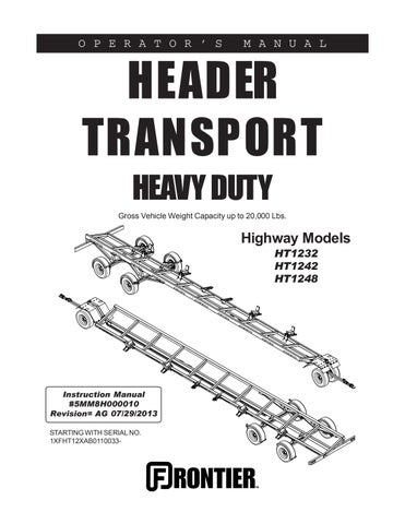
Step 1:
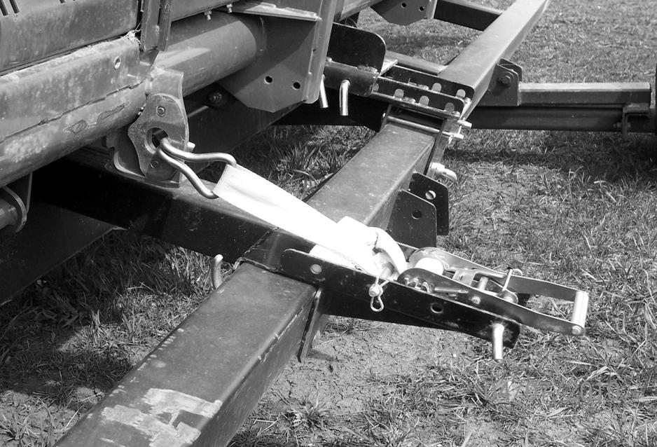
Always position tie-down brackets on bottom rail of transport to create a straight line of pull. (See picture to the left.) Fasten tie-down brackets to bottom rail using carriage bolt and handle nut. Tighten handle nuts to prevent brackets from sliding.
CAUTIONTOPROPERLYSECURE HEADERTOTRANSPORT,BOTHBRACKETS ANDSTRAPSMUSTBEUSED.
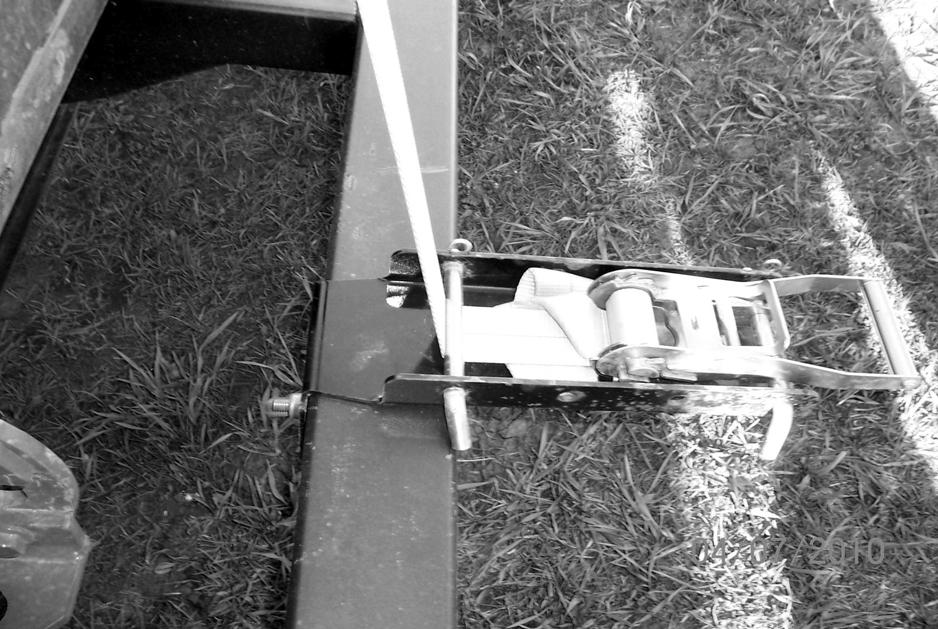
Step 2: Remove nylon tie-down strap from ratchet. Feed the tail end through the nylon loop on the opposite end, to create a slipknot around the feeder house bar of the combine header. (See picture to the left.)
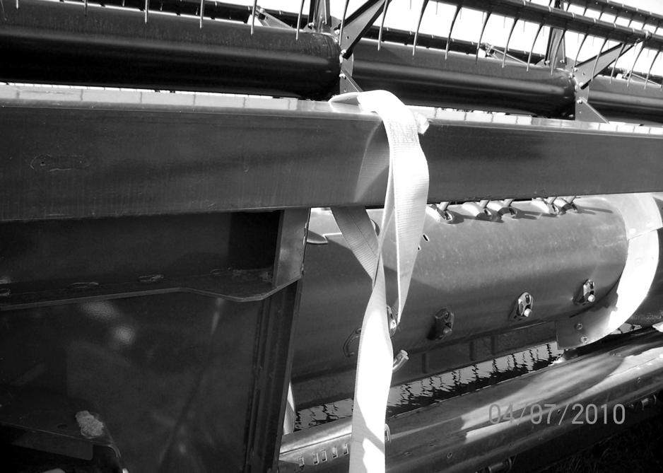
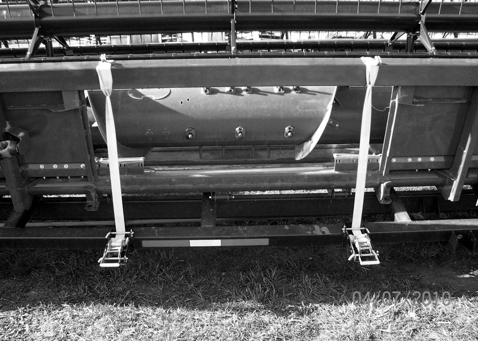
Step 3:
Feed tail end of strap through the drum slot on the ratchet. Pull tail end through tight and ratchet the connection tightly. (See picture to the left.)
Caution
BEAWAREOFTRANSPORTWIDTHWHILETRAVELINGONROADS ANDBEFORECROSSINGBRIDGES.
Operator must comply with all state and local laws governing highway safety regulations while operating on public roads.
Step 4:
Tie-downs are provided long to accommodate different types of headers, and could be cut down and singed, to meet your specific application.
Caution
Preventnylon
STRAPSFROMCONTACTINGANDRUBBING ONSHARPEDGES.REPLACECUTORWORN STRAPSBEFOREOPERATINGEQUIPMENT.
Step 5:
Tie-downs are also provided with a hook to accommodate different types of headers. Hooks can be placed through main frame holes on the header. (See picture to the left.)
Adjustable Tie-Down
17 MM5H00005 51r arrie C Tire Spare HT
Please order replacement parts by Part Number and Description.
* 11 MMU0000001 51W MW Holder Manifest
20 MMR0000005 52p Ca Plastic 7GA X 4 X 4 a 29 MMR0000004 52) (HT1248 Cap Plastic 8-11GA X 1/2 3 X 1/2 3 31 MMR0000005 52p Ca Tube Plastic 1/8" X 6 X 4
4 5MMAT78E15PH 2N DW 5 22 TOR,7K,865,EL,EZ,91X76,
5 MMTCHSJ808E 56E LR 8B IMP SLV W/HTCHI ST 235/80R16
6* MM8H000010 512 HT1 Manual O&M Transport Highway - FHTHD
* 70 MMQAB06502 52e Larg - Sticker Logo Frontier FHT
* 80 MMQAD06502 51l Smal - Sticker Logo Frontier FHT
* 90 MMQBQ06502 51l X-Smal - Sticker Logo Frontier FHT
0a* 12 MMQAB06523 522 HT123 Large - Sticker HT1232 FHT
0b* 12 MMQAB06524 522 HT124 Large - Sticker HT1242 FHT
0c* 18 MMQAB06524 528 HT124 Large - Sticker HT1248 FHT
1a* 12 MMQAD06523 522 HT123 Small - Sticker HT1232 FHT
1b* 12 MMQAD06524 522 HT124 Small - Sticker HT1242 FHT
1c* 18 MMQAD06524 528 HT124 Small - Sticker HT1248 FHT
2* 11 MMQAP06500 51r Sticke Number Serial Highway FHT
3* 10 MMQAS00000 5**e Tap Conspicuity Red/Wht 3M
4* 15 MMQBC01506 51e Whit On Sticker-Red Gun Grease
5 13 MM5H00021 54G
* NOT SHOWN
Please order replacement parts by Part Number and Description.
Notes:
1.The (Back-up) and (+ Positive) terminal of the 7-RV plug are not used.
2.The black wire is to be terminated and not hooked into the 7-RV plug.
3.The black wire is only used between the break-away switch and the break-away battery.
7-POLE
RVPLUG feR o Nr ebmutNra Py t Qn oitpircse D 10 MMEK016416 512 HT1 Brakes 0 - Kit Light Hwy -38'-42' 32 20 MMEK016417 512 HT1 Axle Brake Rear 1 - Hwy -38'-42' 32 30 MMEK016418 512 HT1 Axle Brake Rear 2 - Hwy -38'-42' 32 40 MMEK047870 512 HT1 (Steer) Axle Brake Front - Hwy -38'-42' 32 50 MMEX989024 51e Tongu - Harness Electric FHT12 68 MMEX401022 512 32-4 Driver - M/CLight Fender - Harness Electric FHT12 a 62 MMEX401025 518 4 Driver, - M/CLight Fender - Harness Electric FHT12 76 MMEX401027 512 32-4 Passenger, - M/CLight Fender - Harness Electric FHT12 a 72 MMEX401031 518 Passenger,4 - M/CLight Fender - Harness Electric FHT12 81 MMEX460008 52r Passenge - Brake Axle Rear - Harness Electric FHT12 92 MMEX460004 52r Drive - Brake Axle Rear - Harness Electric FHT12 0 10 MMEK016415 512 HT1 Brakes 0 - Kit Light Highway 48 1 10 MMEK060410 512 HT1 Axle Brake Rear 2 - Highway 48' 2 10 MMEK060420 512 HT1 (Steer) Axle Brake Front - Highway 48' 5
MAXIMUM TRANSPORT SPEED = Posted roadway speeds.
Tire Safety
Failure to follow proper procedures when mounting a tire on a rim can produce an explosion which may result in a serious injury or death.
Do not attempt to mount a tire unless you have proper equipment and experience to do job. Inflating or servicing tires can be dangerous. Whenever possible, trained personnel should be called to service and/or mount tires.
Always order and install tires and wheels with appropriate type and load capacity to meet or exceed anticipated weight to be placed on the equipment.
Head Transport Checklist
Downtime in the fields caused by field breakdowns is costly and time consuming. Many breakdowns can be eliminated by periodic equipment maintenance. By spending a little time running over this checklist, following proper after-season care, you can save time and money later on.
Warning: To prevent Serious Injury or Death
•Make sure ALL guards and shields are in place.
•Keep hands, feet, and loose clothing away from rotating parts.
Before Going to the Field
1.Visually Inspect
•Inspect tires for cracks and worn spots.
• Inspect head transport, make sure that all guards are in place and in good shape.
• Inspect for any loose bolts, worn parts, or cracked welds, and make any necessary repairs.
• Inspect tie-downs for cuts.
2.Check
• Tires for proper inflation.
• Lug nuts for proper torque.
• Lights for proper operation.
• Zerk locations, wheel bearings, and grease as needed.
• All guards and shields. Replace or repair if necessary to insure proper protection.
3.Replacement Parts
• Replace all worn or damaged parts.
• Replace tie-downs if cuts exist.
After Season Care
• Grease all zerk locations.
• Repack wheel bearings before storage.
• Inspect tires for punctures, holes or any other type of leak and repair as needed.
Maximum Towing Speed
The ST235/80R16 Import Radial tires are stamped (DOT). This signifies that the tire has passed the required Department of Transportation (DOT) tests for posted highway speeds.
Dealer Instructions
Dealer Checklist
(Dealer’s Responsibility)
Inspect the equipment thoroughly to be certain it is set up properly before delivering it to the customer. The following checklist is a reminder of points to inspect.
Check off each item if it is found satisfactory or after proper adjustment is made.
Note: It is important for the dealer to visually check and make sure all parts are intact prior to delivery to customer.
___Check that all safety decals are installed and in good condition. Replace if damaged.
___Check that all cotter pins and safety pins are properly installed.
___Show the customer the safe, proper procedures to be used when mounting, dismounting, and storing equipment.
___Show customer how to make adjustments.
___Present Owner’s/Operator’s Manual and request that the customer and all operators read it before operating equipment. Point out the manual safety rules, explain their meanings and emphasize the increased safety hazards that exist when safety rules are not followed.
___Point out safety decals. Explain their meaning and the need to keep them in place and in good condition. Emphasize the increased safety hazards when instructions are not followed.
___Explain to customer the potential crushing hazards of going underneath raised equipment. Instruct customer that service work does not require going underneath unit and never to do so.