17 minute read
Troubleshooting


Common Problems
Use the following procedure as a guide for computer problems. NOTE: The diagnostic tests are intended to test only Acer products. Non-Acer products, prototype cards, or modified options can give false errors and invalid system responses. 1. Obtain the failing symptoms in as much detail as possible. 2. Verify the symptoms by attempting to re-create the failure by running the diagnostic test or by repeating the same operation. 3. Use the following table with the verified symptom to determine which page to go to.
4. If the Issue is still not resolved, see “Online Support Information” on page 185.
Symptoms (Verified) Go To
Power On Issue Page 92 No Display Issue Page 93 LCD Failure Page 96 Internal Keyboard Failure Page 97 TouchPad Failure Page 98 Internal Speaker Failure Page 99 Internal Microphone Failure Page 101 Right Side USB Failure Page 103 Other Functions Failure Page 105 Intermittent Problems Page 105 Undetermined Problems Page 105
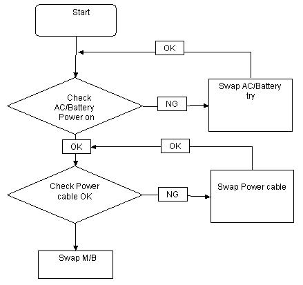
If the system doesn’t power on, perform the following actions one at a time to correct the problem. Do not replace a non-defective FRU:
Computer Shuts Down Intermittently
If the system powers off at intervals, perform the following actions one at a time to correct the problem. 1. Check the power cable is properly connected to the computer and the electrical outlet. 2. Remove any extension cables between the computer and the outlet. 3. Remove any surge protectors between the computer and the electrical outlet. Plug the computer directly into a known good electrical outlet. 4. Remove all external and non-essential hardware connected to the computer that are not necessary to boot the computer to the failure point. 5. Remove any recently installed software. 6. If the Issue is still not resolved, see “Online Support Information” on page 185.
If the Display doesn’t work, perform the following actions one at a time to correct the problem. Do not replace a non-defective FRUs:

No POST or Video
If the POST or video doesn’t display, perform the following actions one at a time to correct the problem. 1. Make sure that the internal display is selected. On this notebook model, switching between the internal display and the external display is done by pressing Fn+F5. Reference Product pages for specific model procedures. 2. Make sure the computer has power by checking at least one of the following occurs: • Fans start up • Status LEDs light up
If there is no power, see “Power On Issue” on page 92. 3. Drain any stored power by removing the power cable and battery and holding down the power button for 10 seconds. Reconnect the power and reboot the computer. 4. Connect an external monitor to the computer and switch between the internal display and the external display is by pressing Fn+F5 (on this model).
If the POST or video appears on the external display, see “LCD Failure” on page 96. 5. Disconnect power and all external devices including port replicators or docking stations. Remove any memory cards and CD/DVD discs. Restart the computer.
If the computer boots correctly, add the devices one by one until the failure point is discovered. 6. Reseat the memory modules.
7. Remove the drives (see “Disassembly Process” on page 40). 8. If the Issue is still not resolved, see “Online Support Information” on page 185.
Abnormal Video Display
If video displays abnormally, perform the following actions one at a time to correct the problem. 1. Reboot the computer. 2. If permanent vertical/horizontal lines or dark spots display in the same location, the LCD is faulty and should be replaced. See “Disassembly Process” on page 40. 3. If extensive pixel damage is present (different colored spots in the same locations on the screen), the LCD is faulty and should be replaced. See “Disassembly Process” on page 40. 4. Adjust the brightness to its highest level. See the User Manual for instructions on adjusting settings.
NOTE: Ensure that the computer is not running on battery alone as this may reduce display brightness.
If the display is too dim at the highest brightness setting, the LCD is faulty and should be replaced. See
“Disassembly Process” on page 40. 5. Check the display resolution is correctly configured: a. Minimize or close all Windows. b. If display size is only abnormal in an application, check the view settings and control/mouse wheel zoom feature in the application. c. If desktop display resolution is not normal, right-click on the desktop and select Personalize Display Settings. d. Click and drag the Resolution slider to the desired resolution. e. Click Apply and check the display. Readjust if necessary. 6. Roll back the video driver to the previous version if updated. 7. Remove and reinstall the video driver. 8. Check the Device Manager to determine that: • The device is properly installed. There are no red Xs or yellow exclamation marks. • There are no device conflicts. • No hardware is listed under Other Devices. 9. If the Issue is still not resolved, see “Online Support Information” on page 185. 10. Run the Windows Memory Diagnostic from the operating system DVD and follow the onscreen prompts. 11. If the Issue is still not resolved, see “Online Support Information” on page 185.
If the computer is experiencing intermittent loss of BIOS information, perform the following actions one at a time to correct the problem. 1. If the computer is more than one year old, replace the CMOS battery. 2. Run a complete virus scan using up-to-date software to ensure the computer is virus free. 3. If the computer is experiencing HDD or ODD BIOS information loss, disconnect and reconnect the power and data cables between devices.
If the BIOS settings are still lost, replace the cables. 4. If HDD information is missing from the BIOS, the drive may be defective and should be replaced. 5. Replace the Motherboard. 6. If the Issue is still not resolved, see “Online Support Information” on page 185.
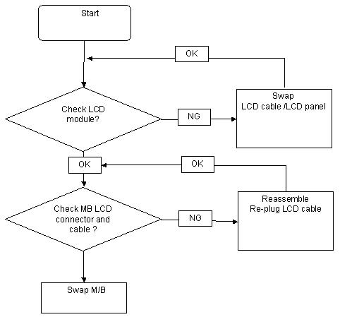
If the LCD fails, perform the following actions one at a time to correct the problem. Do not replace a nondefective FRUs:
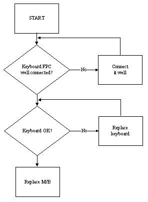
If the built-in Keyboard fails, perform the following actions one at a time to correct the problem. Do not replace a non-defective FRUs:
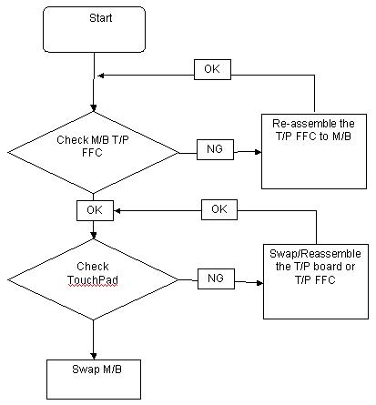
If the TouchPad doesn’t work, perform the following actions one at a time to correct the problem. Do not replace a non-defective FRUs:
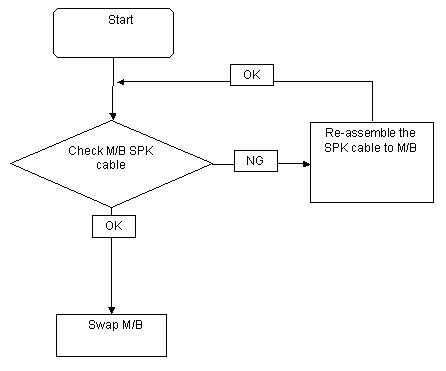
If the internal Speakers fail, perform the following actions one at a time to correct the problem. Do not replace a non-defective FRUs:
Sound Problems
If sound problems are experienced, perform the following actions one at a time to correct the problem. 1. Reboot the computer. 2. Navigate to Start Control Panel System and Maintenance System Device Manager. Check the Device Manager to determine that: • The device is properly installed. • There are no red Xs or yellow exclamation marks. • There are no device conflicts. • No hardware is listed under Other Devices. 3. Roll back the audio driver to the previous version, if updated recently. 4. Remove and reinstall the audio driver. 5. Ensure that all volume controls are set mid range: a. Click the volume icon on the taskbar and drag the slider to 50. Ensure that the volume is not muted. b. Click Mixer to verify that other audio applications are set to 50 and not muted. 6. Navigate to Start Control Panel Hardware and Sound Sound. Ensure that Speakers are selected as the default audio device (green check mark).
NOTE: If Speakers does not show, right-click on the Playback tab and select Show Disabled Devices (clear by default). 7. Select Speakers and click Configure to start Speaker Setup. Follow the onscreen prompts to configure the speakers. 8. Remove and recently installed hardware or software.
9. Restore system and file settings from a known good date using System Restore.
If the issue is not fixed, repeat the preceding steps and select an earlier time and date. 10. Reinstall the Operating System. 11. If the Issue is still not resolved, see “Online Support Information” on page 185.
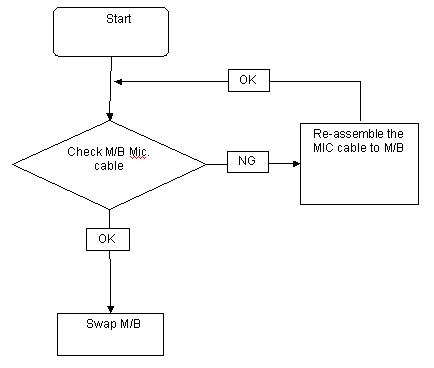
If the internal Microphone fails, perform the following actions one at a time to correct the problem. Do not replace a non-defective FRUs:
Microphone Problems
If internal or external Microphones do no operate correctly, perform the following actions one at a time to correct the problem. 1. Check that the microphone is enabled. Navigate to Start Control Panel Hardware and Sound
Sound and select the Recording tab. 2. Right-click on the Recording tab and select Show Disabled Devices (clear by default). 3. The microphone appears on the Recording tab. 4. Right-click on the microphone and select Enable. 5. Select the microphone then click Properties. Select the Levels tab. 6. Increase the volume to the maximum setting and click OK. 7. Test the microphone hardware: a. Select the microphone and click Configure. b. Select Set up microphone. c. Select the microphone type from the list and click Next. d. Follow the onscreen prompts to complete the test. 8. If the Issue is still not resolved, see “Online Support Information” on page 185.
If the HDD does not operate correctly, perform the following actions one at a time to correct the problem. 1. Disconnect all external devices. 2. Run a complete virus scan using up-to-date software to ensure the computer is virus free. 3. Run the Windows Vista Startup Repair Utility: a. insert the Windows Vista Operating System DVD in the ODD and restart the computer. b. When prompted, press any key to start to the operating system DVD. c. The Install Windows screen displays. Click Next. d. Select Repair your computer. e. The System Recovery Options screen displays. Click Next. f. Select the appropriate operating system, and click Next.
NOTE: Click Load Drivers if controller drives are required. g. Select Startup Repair. h. Startup Repair attempts to locate and resolve issues with the computer. i. When complete, click Finish.
If an issue is discovered, follow the onscreen information to resolve the problem. 4. Run the Windows Memory Diagnostic Tool. For more information see Windows Help and Support. 5. Restart the computer and press F2 to enter the BIOS Utility. Check the BIOS settings are correct and that
CD/DVD drive is set as the first boot device on the Boot menu. 6. Ensure all cables and jumpers on the HDD and ODD are set correctly. 7. Remove any recently added hardware and associated software. 8. Run the Windows Disk Defragmenter. For more information see Windows Help and Support. 9. Run Windows Check Disk by entering chkdsk /r from a command prompt. For more information see
Windows Help and Support. 10. Restore system and file settings from a known good date using System Restore.
If the issue is not fixed, repeat the preceding steps and select an earlier time and date. 11. Replace the HDD. See “Disassembly Process” on page 40.
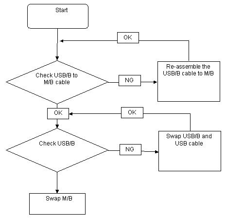
If the rightside USB port fails, perform the following actions one at a time to correct the problem. Do not replace a non-defective FRUs:
If an external Mouse fails, perform the following actions one at a time to correct the problem. 1. Try an alternative mouse. 2. If the mouse uses a wireless connection, insert new batteries and confirm there is a good connection. See the mouse user manual. 3. If the mouse uses a USB connection, try an alternate USB port. 4. Try an alternative program to verify mouse operation. Reinstall the program experiencing mouse failure. 5. Restart the computer. 6. Remove any recently added hardware and associated software. 7. Remove any recently added software and reboot. 8. Restore system and file settings from a known good date using System Restore.
If the issue is not fixed, repeat the preceding steps and select an earlier time and date. 9. Run the Event Viewer to check the events log for errors. For more information see Windows Help and
Support. 10. Roll back the mouse driver to the previous version if updated recently. 11. Remove and reinstall the mouse driver. 12. Check the Device Manager to determine that: • The device is properly installed. There are no red Xs or yellow exclamation marks. • There are no device conflicts. • No hardware is listed under Other Devices. 13. If the Issue is still not resolved, see “Online Support Information” on page 185.
If the CRT Switch, Dock, LAN Port, external MIC or Speakers, PCI Express Card, 5-in-1 Card Reader or Volume Wheel fail, perform the following general steps to correct the problem. Do not replace a non-defective FRUs: 1. Check Drive whether is OK. 2. Check Test Fixture is ok. 3. Swap M/B to Try.
Intermittent Problems
Intermittent system hang problems can be caused by a variety of reasons that have nothing to do with a hardware defect, such as: cosmic radiation, electrostatic discharge, or software errors. FRU replacement should be considered only when a recurring problem exists. When analyzing an intermittent problem, do the following: 1. Run the advanced diagnostic test for the system board in loop mode at least 10 times. 2. If no error is detected, do not replace any FRU. 3. If any error is detected, replace the FRU. Rerun the test to verify that there are no more errors.
Undetermined Problems
The diagnostic problems does not identify which adapter or device failed, which installed devices are incorrect, whether a short circuit is suspected, or whether the system is inoperative. Follow these procedures to isolate the failing FRU (do not isolate non-defective FRU). NOTE: Verify that all attached devices are supported by the computer. NOTE: Verify that the power supply being used at the time of the failure is operating correctly. (See “Power On Issue” on page 92): 1. Power-off the computer. 2. Visually check them for damage. If any problems are found, replace the FRU. 3. Remove or disconnect all of the following devices: • Non-Acer devices • Printer, mouse, and other external devices • Battery pack • Hard disk drive • DIMM • CD-ROM/Diskette drive Module • PC Cards 4. Power-on the computer. 5. Determine if the problem has changed. 6. If the problem does not recur, reconnect the removed devices one at a time until you find the failing FRU. 7. If the problem remains, replace the following FRU one at a time. Do not replace a non-defective FRU: • System board • LCD assembly
These tables describe the POST codes and components of the POST process.
Chipset POST Codes
The following table details the chipset POST codes and functions used in the POST.
Code Beeps POST Routine Description
02h Verify Real Mode 03h Disable Non-Maskable Interrupt (NMI) 04h Get CPU type 06h Initialize system hardware 08h Initialize chipset with initial POST values 09h Set IN POST flag 0Ah Initialize CPU registers 0Bh Enable CPU cache 0Ch Initialize caches to initial POST values 0Eh Initialize I/O component 0Fh Initialize the local bus IDE 10h Initialize Power Management 11h Load alternate registers with initial POST values 12h Restore CPU control word during warm boot 13h Initialize PCI Bus Mastering devices 14h Initialize keyboard controller 16h 1-2-2-3 BIOS ROM checksum 17h Initialize cache before memory autosize 18h 8254 timer initialization 1Ah 8237 DMA controller initialization 1Ch Reset Programmable Interrupt Controller 20h 1-3-1-1 Test DRAM refresh 22h 1-3-1-3 Test 8742 Keyboard Controller 24h Set ES segment register to 4 GB 26h Enable A20 line 28h Autosize DRAM 29h Initialize POST Memory Manager 2Ah Clear 512 KB base RAM 2Ch 1-3-4-1 RAM failure on address line xxxx* 2Eh 1-3-4-3 RAM failure on data bits xxxx* of low byte of memory bus 2Fh Enable cache before system BIOS shadow 30h 1-4-1-1 RAM failure on data bits xxxx* of high byte of memory bus 32h Test CPU bus-clock frequency 33h Initialize Phoenix Dispatch Manager 36h Warm start shut down 38h Shadow system BIOS ROM 3Ah Autosize cache
3Ch 3Dh 42h
Advanced configuration of chipset registers Load alternate registers with CMOS values Initialize interrupt vectors 45h POST device initialization 46h 2-1-2-3 Check ROM copyright notice 48h Check video configuration against CMOS 49h Initialize PCI bus and devices
4Ah 4Bh 4Ch 4Eh 50h 51h Initialize all video adapters in system QuietBoot start (optional) Shadow video BIOS ROM Display BIOS copyright notice Display CPU type and speed Initialize EISA board
52h
Test keyboard 54h Set key click if enabled 58h 2-2-3-1 Test for unexpected interrupts 59h Initialize POST display service 5Ah Display prompt Press F2 to enter SETUP 5Bh Disable CPU cache
5Ch Test RAM between 512 and 640 KB
60h 62h 64h 66h 67h 68h 69h 6Ah 6Bh 6Ch 6Eh 70h 72h 76h 7Ch 7Eh 80h 81h 82h 83h 84h 85h 86h Test extended memory Test extended memory address lines Jump to UserPatch1 Configure advanced cache registers Initialize Multi Processor APIC Enable external and CPU caches Setup System Management Mode (SMM) area Display external L2 cache size Load custom defaults (optional) Display shadow-area message Display possible high address for UMB recovery Display error messages Check for configuration errors Check for keyboard errors Set up hardware interrupt vectors Initialize coprocessor if present Disable onboard Super I/O ports and IRQs Late POST device initialization Detect and install external RS232 ports Configure non-MCD IDE controllers Detect and install external parallel ports Initialize PC-compatible PnP ISA devices Re-initialize onboard I/O ports.
Code Beeps
87h 88h 89h 8Ah 8Bh 8Ch 8Fh 90h 91h
POST Routine Description
Configure Motherboard Configurable Devices (optional) Initialize BIOS Data Area Enable Non-Maskable Interrupts (NMIs) Initialize Extended BIOS Data Area Test and initialize PS/2 mouse Initialize floppy controller Determine number of ATA drives (optional) Initialize hard-disk controllers Initialize local-bus hard-disk controllers
92h 93h 95h Jump to UserPatch2 Build MPTABLE for multi-processor boards Install CD ROM for boot
96h
Clear huge ES segment register 97h Fixup Multi Processor table 98h 1-2 Search for option ROMs. One long, two short beeps on checksum failure 99h Check for SMART Drive (optional) 9Ah Shadow option ROMs 9Ch Set up Power Management 9Dh Initialize security engine (optional) 9Eh Enable hardware interrupts 9Fh Determine number of ATA and SCSI drives A0h Set time of day A2h Check key lock A4h Initialize Typematic rate A8h Erase F2 prompt AAh Scan for F2 key stroke ACh Enter SETUP AEh Clear Boot flag B0h Check for errors B2h POST done - prepare to boot operating system B4h 1 One short beep before boot B5h Terminate QuietBoot (optional) B6h Check password (optional) B9h Prepare Boot BAh Initialize DMI parameters BBh Initialize PnP Option ROMs BCh Clear parity checkers BDh Display MultiBoot menu BEh Clear screen (optional) BFh Check virus and backup reminders C0h Try to boot with INT 19 C1h Initialize POST Error Manager (PEM) C2h Initialize error logging
Code Beeps
C3h C4h C5h C6h C7h C8h C9h D2h
POST Routine Description
Initialize error display function Initialize system error handler PnPnd dual CMOS (optional) Initialize notebook docking (optional) Initialize notebook docking late Force check (optional) Extended checksum (optional) Unknown interrupt
Code Beeps For Boot Block in Flash ROM
E0h Initialize the chipset E1h Initialize the bridge E2h Initialize the CPU E3h Initialize system timer E4h Initialize system I/O E5h Check force recovery boot E6h Checksum BIOS ROM E7h Go to BIOS E8h Set Huge Segment E9h Initialize Multi Processor EAh Initialize OEM special code EBh Initialize PIC and DMA ECh Initialize Memory type EDh Initialize Memory size EEh Shadow Boot Block EFh System memory test F0h Initialize interrupt vectors F1h Initialize Run Time Clock F2h Initialize video F3h Initialize System Management Mode F4h 1 Output one beep before boot F5h Boot to Mini DOS F6h Clear Huge Segment F7h Boot to Full DOS
* If the BIOS detects error 2C, 2E, or 30 (base 512K RAM error), it displays an additional word-bitmap (xxxx) indicating the address line or bits that failed. For example, 2C 0002 means address line 1 (bit one set) has failed. 2E 1020 means data bits 12 and 5 (bits 12 and 5 set) have failed in the lower 16 bits. Note that error 30 cannot occur on 386SX systems because they have a 16 rather than 32-bit bus. The BIOS also sends the bitmap to the port-80 LED display. It first displays the check point code, followed by a delay, the high-order byte, another delay, and then the low-order byte of the error. It repeats this sequence continuously.