1 minute read
TYPICAL PAGE – D


INTRODUCTION
TYPICAL PAGE – D
Two pulse hoses connect the pump to pulse fittings on the front of the cylinder/crankcase. • V4 Models – cylinders 1 and 3 • V6 Models – cylinders 1 and 4
1
TYPICAL
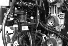
1. Lower pulse hose
000721
Oil Injector-ManifoldTypical illustration for The oil injector-manifold distributes the oil sup-lower pulse hose of plied by the oil lift pump. A pressure-sensingV4 or V6 Models switch monitors oil injection pressure.
Oil Injector-Manifold Components
• 40V oil injector Cross references • • Oil distribution manifold Oil pressure switch direct readers to related topics • Pressure regulator (oil return hose) • Oil distribution hoses • Oil to fuel check valve
3
1 3

2
4
TYPICAL
1. Oil injector 2. Oil distribution manifold 3. Oil distribution hoses 4. Oil to fuel check valve
000722
OILING SYSTEM
COMPONENTS
Oil Pressure Switch
The oil pressure switch is located in the oil injector-manifold and reacts to changes in oil manifold pressure. The EMM supplies and monitors electrical current to the switch.
The switch opens or closes based on the following oil manifold pressures:
1
TYPICAL
1. Oil pressure switch
Illustration 000723 components numbered to correspond to image
53 psi (365 kPa) (nominal) to close 43 psi (296 kPa) (nominal) to reopen
Refer to Oil Pressure Switch Test on p.224.
Service Code 38
A faulty electrical circuit or an inoperative pressure switch activates service code 38 (no oil sensor feedback or lack of oil pressure) and the EMM:
8
Activates the System Check "NO OIL" light Stores a service code Initiates S.L.O.W.
Service Code 39
If no oil pressure is detected during startup, the EMM initiates an oil injector “recovery mode” to pressurize the system. If inadequate oil pressure is still detected after the recovery mode is completed, the EMM:
Section tabs allow for quicker reference when thumbing through manual
Activates the System Check "NO OIL" light Stores a service code Initiates S.L.O.W.
209