12 minute read
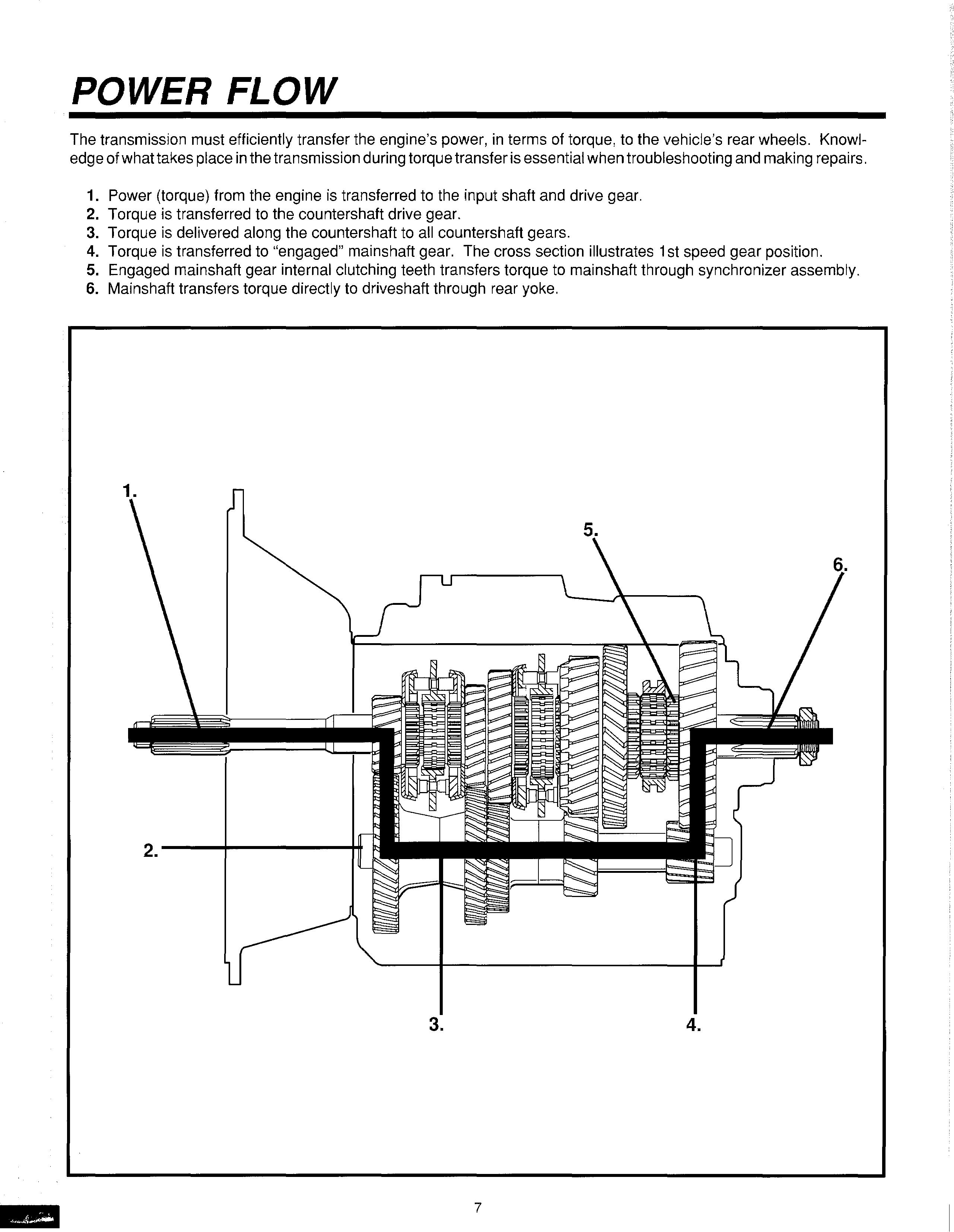
PREVENTIVE MAINTENANCE

Preventive Maintenance Check Chart
CHECKS WITHOUT PARTIAL DISASSEMBLY OF CHASSIS OR CAB
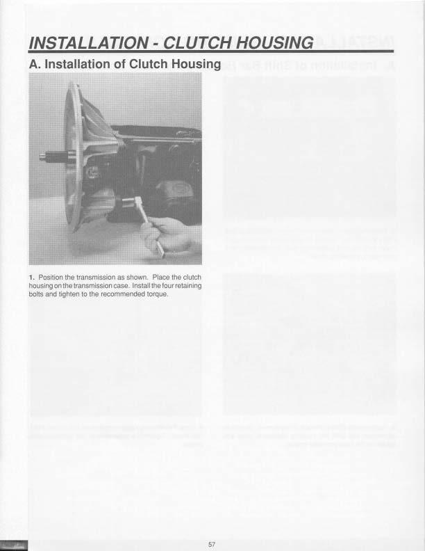
1. Clutch Housing Mounting
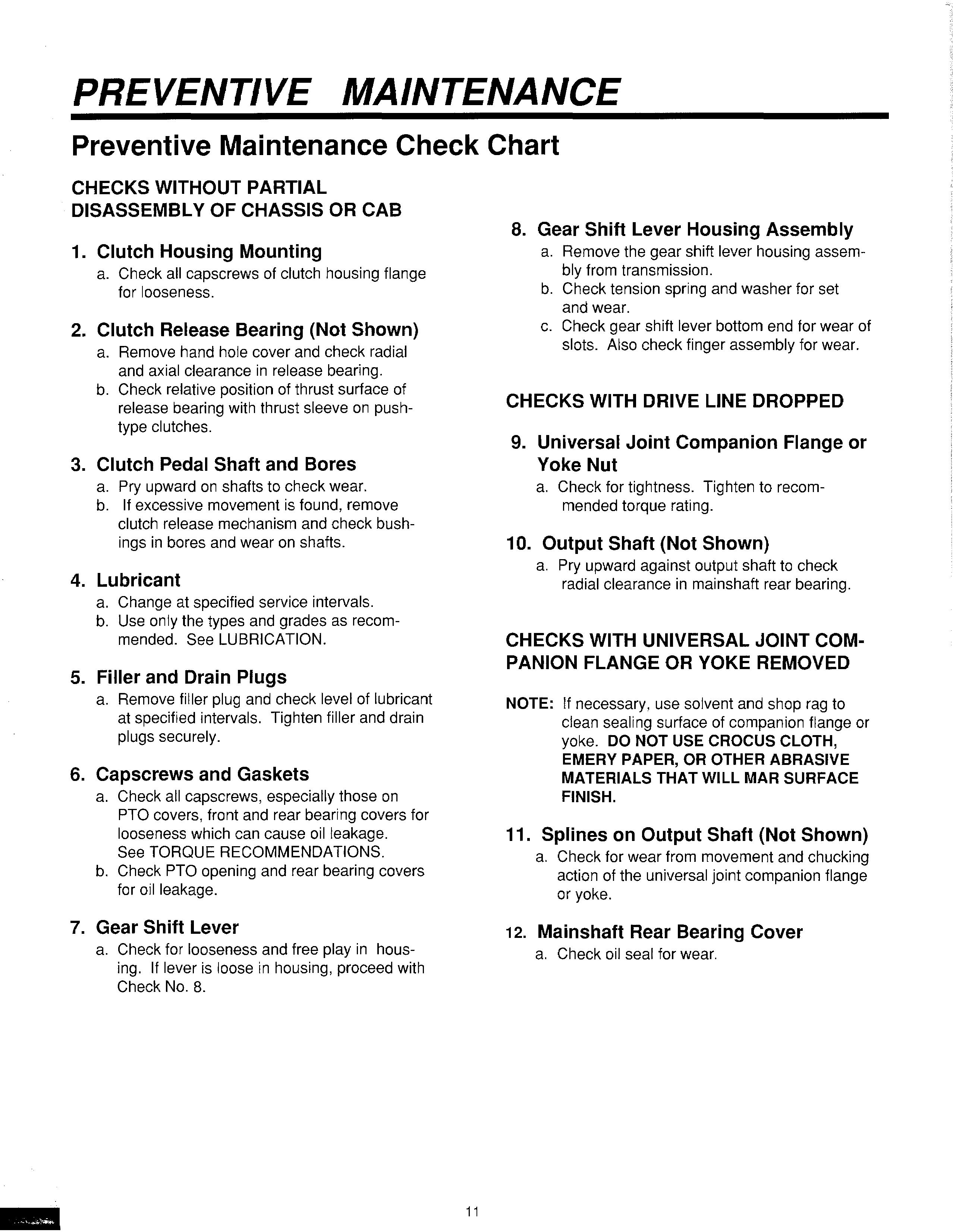
a. Check all capscrews of clutch housing flange for looseness.
2. Clutch Release Bearing (Not Shown)
a. Remove hand hole cover and check radial and axial clearance in release bearing. b. Check relative position of thrust surface of release bearing with thrust sleeve on pushtype clutches.
3. Clutch Pedal Shaft and Bores
a. Pry upward on shafts to check wear. b. If excessive movement is found, remove clutch release mechanism and check bushings in bores and wear on shafts.
4. Lubricant
a. Change at specified service intervals. b. Use only the types and grades as recommended. See LUBRICATION.
5. Filler and Drain Plugs
a. Remove filler plug and check level of lubricant at specified intervals. Tighten filler and drain plugs securely.
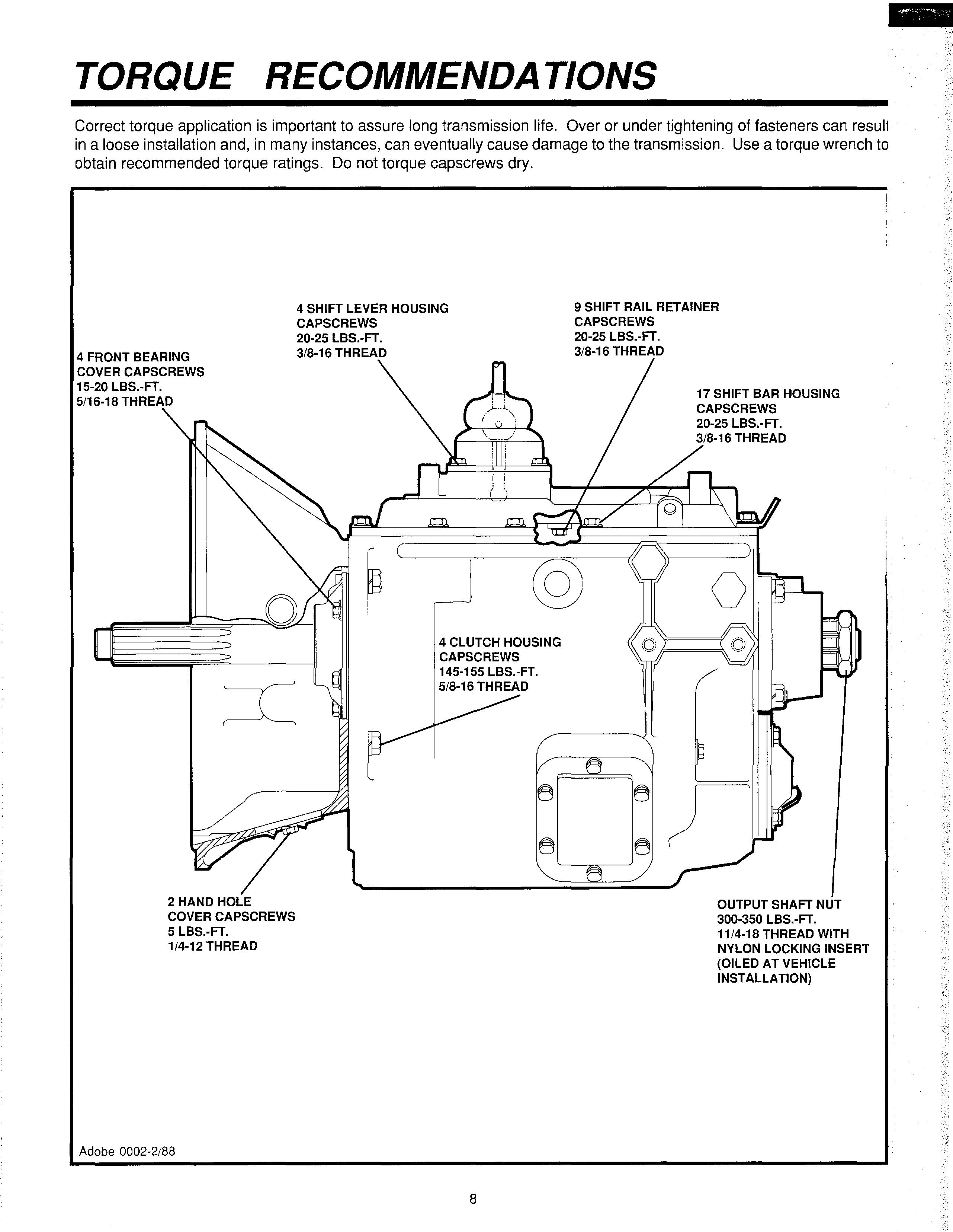
6. Capscrews and Gaskets
a. Check all capscrews, especially those on
PTO covers, front and rear bearing covers for looseness which can cause oil leakage.
See TORQUE RECOMMENDATIONS. b. Check PTO opening and rear bearing covers for oil leakage.
7. Gear Shift Lever
a. Check for looseness and free play in housing. If lever is loose in housing, proceed with
Check No. 8.
8. Gear Shift Lever Housing Assembly
a. Remove the gear shift lever housing assembly from transmission. b. Check tension spring and washer for set and wear. c. Check gear shift lever bottom end for wear of slots. Also check finger assembly for wear.
CHECKS WITH DRIVE LINE DROPPED
9. Universal Joint Companion Flange or
Yoke Nut
a. Check for tightness. Tighten to recommended torque rating.
10. Output Shaft (Not Shown)
a. Pry upward against output shaft to check radial clearance in mainshaft rear bearing.
NOTE: If necessary, use solvent and shop rag to clean sealing surface of companion flange or yoke. DO NOT USE CROCUS CLOTH,
EMERY PAPER, OR OTHER ABRASIVE MATERIALS THAT WILL MAR SURFACE FINISH.
11. Splines on Output Shaft (Not Shown)
a. Check for wear from movement and chucking action of the universal joint companion flange or yoke.
12. Mainshaft Rear Bearing Cover
a. Check oil seal for wear.
Disassembly
It is assumed in the detailed assembly instructions that the lubricant has been drained from the transmission, the necessary linkage disconnected and the transmission has been removed from vehicle chassis. Removal of the gear shift lever housing assembly is included in the detailed instructions (Disassembly and Reassembly-Shifting Controls); however, this assembly must be detached from shift bar housing before transmission can be removed.
FOLLOW CLOSELY EACH PROCEDURE IN THE DETAILED INSTRUCTIONS, MAKING USE OF THE TEXT, ILLUSTRATIONS, AND PHOTOGRAPHS PROVIDED.
1. BEARINGS-Carefully wash and relubricate all reuseable bearings as removed and protectively wrapped until ready for use. Remove bearings planned to be reused with pullers designed for this purpose.
2. ASSEMBLIES-When disassembling the various assemblies, such as the mainshaft, countershafts, and shift bar housing, lay all parts on a clean bench in the same order as removed. This procedure simplifies reassembly and reduces the possibility of losing parts.
3. SNAP RINGS-Remove snap rings with pliers designed for this purpose. Snap rings removed in this manner can be reused, if they are not sprung or loose. 4. CLEANLINESS-Provide a clean place to work.
It is important that no dirt or foreign material enters the unit during repairs. Dirt is an abrasive and can damage bearings. It is always good practice to clean the outside of the unit before starting the planned disassembly.
5. WHEN USING TOOLS TO MOVE PARTS-
Always apply force to shafts, housings, etc, with restraint. Movement of some parts is restricted.
Never apply force to the part being driven after it stops solidly. The use of soft hammers, bar, and mauls for all disassembly work is recommended.
Before reassembling the transmission, check each part carefully for abnormal or excessive wear and damage to determine reuse or replacement. When replacement is necessary, use only genuine Eaton Fuller Transmission parts to assure continued performance and extended lite from your unit. Since the cost of a new part is generally a small fraction of the total cost of downtime and labor, avoid reusing a questionable part which could lead to additional repairs and expense soon after reassembly. To aid in determining the reuse or replacement of any transmission part, consideration should also be given to the unit's history, mileage, application, etc. Recommended inspection procedures are provided in the following checklist.
Inspection
A. BEARINGS B. GEARS
1. Wash all bearings in clean solvent. Check balls, rollers, and raceways for pitting, discoloration, and spalled areas. Replace bearings that are pitted, discolored, spalled, or damaged during disassembly.
2. Lubricate bearings that are not pitted, discolored, or spalled and check for axial and radial clearances.
Replace bearings with excessive clearances.
3. Check bearing fit. Bearing inner races should be tight to shaft; outer races slightly tight to slightly loose in case bore. If bearing spins freely in bore, case should be replaced. 1. Check gear teeth for frosting and pitting. Frosting of gear teeth faces present no threat of transmission failure. Often in continued operation of the unit, frosted gears "heal" and do not progress to the pitting stage. In most cases, gears with light to moderate pitted teeth have considerable gear life remaining and can be reused, but gears with advanced stage pitting should be replaced.
2. Check for gears with clutching teeth abnormally worn, tapered, or reduced in length from clashing in shifting. Replace gears found in any of these conditions.
PRECAUTIONS
Inspection (cont.)
3. Check axial clearance of gears. Where excessive clearance is found, check gear snap ring, split washer, clutch hub, and gear hub for excessive wear.
C. SPLINES
1. Check splines on all shafts for abnormal wear. If sliding clutch gears, companion flange, or clutch hub have worn into the sides of the splines, replace the specific shaft affected.
D. WASHERS
1. Check surfaces of all washers. Washers scored or reduced in thickness should be replaced.
E. REVERSE IDLER GEAR ASSEMBLIES
1. Check for excessive wear from action of roller bearings.
F. GRAY IRON PARTS
1. Check all gray iron parts tor cracks and breaks.
Replace or repair parts found to be damaged.
Heavy castings may be welded or brazed provided the cracks do not extend into the bearing bores or bolting surfaces. When welding, never place the ground so current passes through the transmission.
G. CLUTCH RELEASE PARTS
1. Check clutch release parts. Replace yokes worn at cam surfaces and bearing carrier worn at contact pads.
2. Check pedal shafts. Replace those worn at bushing surfaces.
H. SHIFT BAR HOUSING ASSEMBLY
1. Check tor wear on shift yokes and finger as sembly at pads and lever slot. Replace excessively worn parts.
2. Check yokes for correct alignment. Replace sprung yokes.
3. Check lockscrews in yoke assembly retainer plates. Tighten those loose.
I. GEAR SHIFT LEVER HOUSING ASSEMBLY
1. Check spring tension on shift lever. Replace tension spring if lever moves too freely.
2. If housing is disassembled, check gear shift lever bottom end and shift finger assembly for wear. Replace both gears if excessively worn.
J. BEARING COVERS
1. Check covers for wear from thrust of adjacent bearing. Replace covers damaged from thrust of bearing outer race.
2. Check cover bores for wear. Replace those worn oversized.
K. OIL SEALS
1. Check oil seal in input shaft and rear bearing cover. It sealing action of lip has been destroyed, replace seal.
L.
1. Check synchronizer for burrs, uneven and excessive wear at contact surface, and metal particles.
2. Check blocker pins for excessive wear or looseness.
3. Check synchronizer contact surfaces on the synchronizer cups for wear.
Reassembly
Make sure that case interiors and housings are clean. It is important that dirt and other foreign materials are kept out of the transmission during reassembly. Dirt is an abrasive and can damage polished surfaces of bearings and washers. Use certain precautions, as listed below, during reassembly.
1. GASKETS-Use new gaskets throughout the transmission as it is being rebuilt. Make sure all gaskets are installed. An omission of any gasket can result in oil leakage or misalignment of bearing covers.
2. CAPSCREWS-To prevent oil leakage and loosening, use Loctite #262 thread sealant on all capscrews. For recommended torque ratings, see TORQUE RECOMMENDATIONS.
3. SHIMS-Apply a light coat of Loctite 51 O to both sides of shims before final installation to prevent leakage.
4. ASSEMBLY-See the illustrations provided in the detailed disassembly instructions as a guide to reassembly. 5. INITIAL LUBRICATION-Coat all thrust washers, synchronizers, and bearings with transmission lubricant during reassembly to prevent damage during initial start up.
6. AXIAL CLEARANCES-Maintain original axial clearances for mainshaft gears.
7. BEARINGS-Using a sleeve type driver that contacts the bearing inner race prevents damage to the rollers and cage.
8. UNIVERSAL JOINT COMPANION FLANGE OR
YOKE-Pull the companion flange or yoke into place with the output shaft nut, using 300-350 lbs.-ft. (407-475 Nm) of torque. Make sure the speed ometer drive gear or a replacement spacer has been installed. Failure to properly torque the nut can result in damage to the mainshaft rear bearing.
IMPORTANT: SEE THE APPROPRIATE ILLUSTRATED PARTS LIST (SPECIFIED BY MODEL SERIES) TO ENSURE THAT PROPER PARTS ARE USED DURING REASSEMBLY OF THE TRANSMISSION.
DISASSEMBLY AND REASSEMBLY SHIFTING CONTROLS
Gearshift Lever Housing Assembly
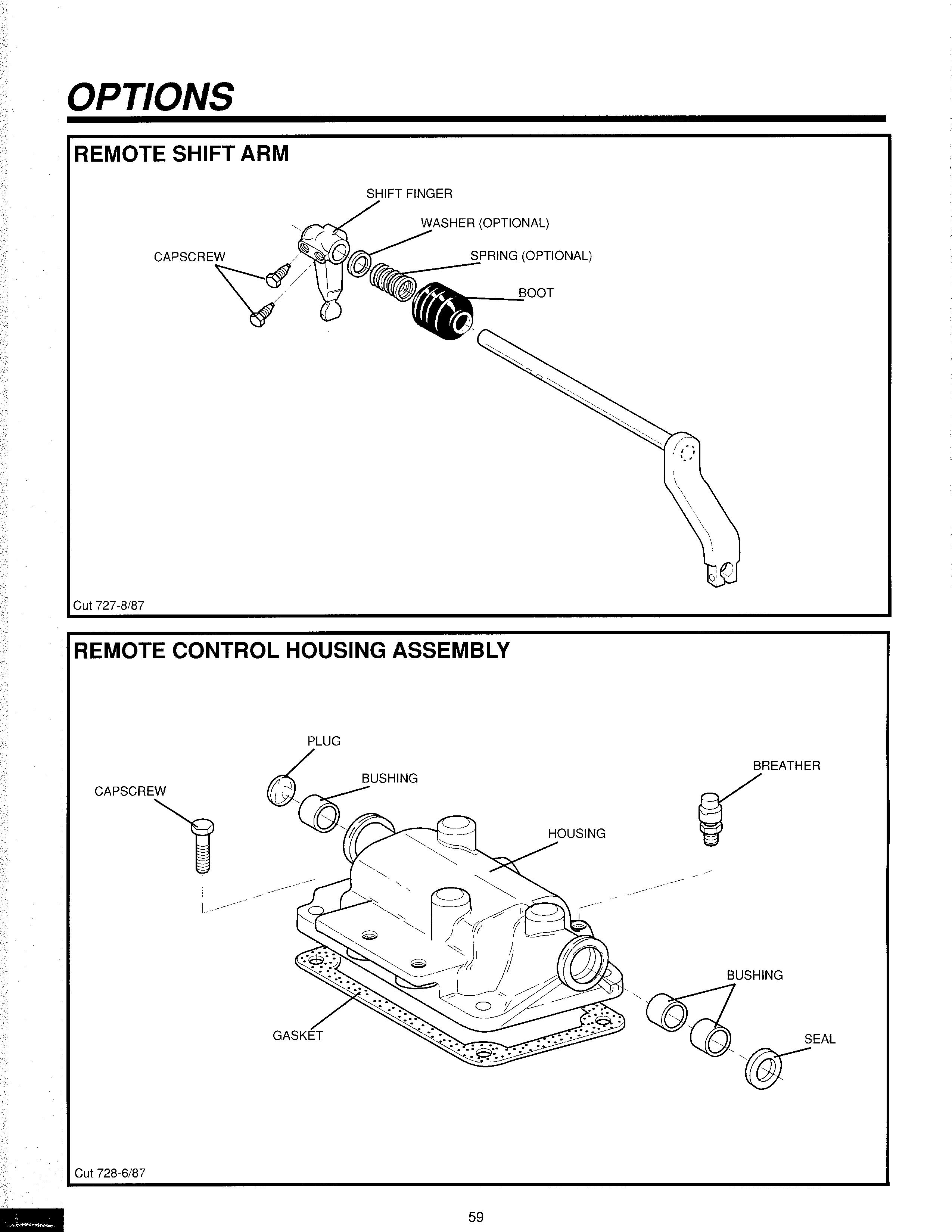
LCV(RGAl=P,---· 9---ousrcovrR
HOUSING
,,...,,,, PIN ):t- _PIN
y"SHJFT LEVE.A
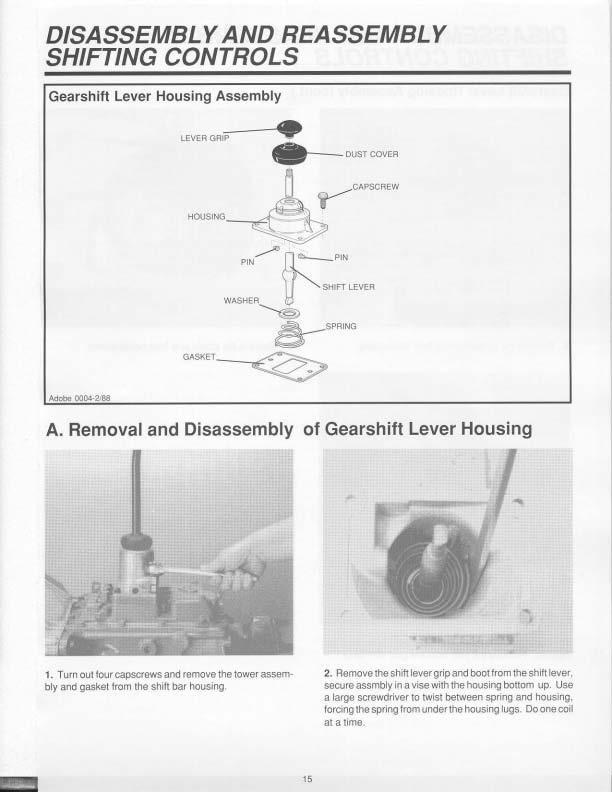
1. T wn ou1 tCMJr capsctews arld remove the tower a5Sembly and gasket from the shllt bar hous.ing 2. Remove the shifl levergripand boo1 from the shift lever, sorure assmbly In a vise with the housing bottom up. Use a large scrc· wdriver to twisi between spnrig and houSJng, forongthe Spl'ing from under tne llovsing lugs-. Dooneooi a1 a lime.
Gearshift Lever Housing Assembly (cont.)
3. Removo tho ten&1on spring trom the haualng 5. Remove the spadO pins lrom housing bo1e.

4, Remove tne wasf'le( and gearshtl\ .. ver trom ttle houM'lg Remove the boot from die gear 1htfl IGVlf
DISASSEMBLY AND REASSEMBLY SHIFTING CONTROLS
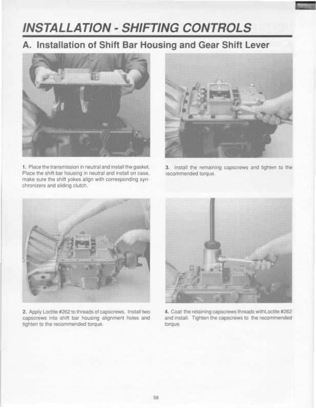
B. Reassembly of Gearshift Lever Housing Assembly
1. Secure 1he gearshift lever housing In a vise, Install the spade pins in housing bore. 3. Use a spMg driving tool to Install tho tension sp<ing under the housing lugs, seating one ooll at a ume

2. POSihon gearshlh lever In housing with the spade pins in 1ho levor ball slot and ins1all the lension spnng washer over tho ball . dlslled side up 4. Remove ass9'mbty lrom lhe vise and tnstaJI lhe rubbe< boot ovEK the gearshlJt klver -and against tt1<I housing, lnsl.all 1he shrf1 lev9I gn.p.
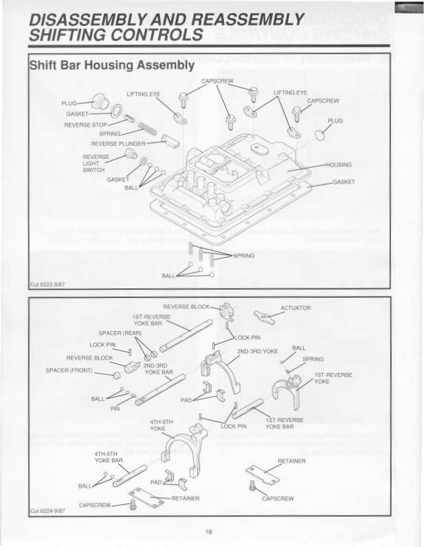
hift Bar Housing Assembly
DISASSEMBLY AND REASSEMBLY SHIFTING CONTROLS
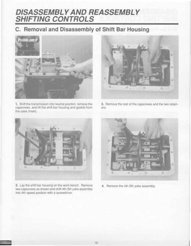
C. Removal and Disassembly of Shift Bar Housing
1. Sh 11100 transmission into neutral po81hon, remove the capscrewa. and I It the shift bar housing and OdSklll honl
11'\c oate (1rigtHI. 3. Rcmo11e tile r8$1 of 1he capsorewS: and tne two retain ors.
2. Uy h ""111>11' _ -· MO capecr9W$ a.s showo and shh )'Ok.o 1:111 n:itf into .&th speed position W'trl a
Shift Bar Housing Disassembly (cont.)
5. Remove 2nd-3rd yoke assembly and lnteflock pin
(Inset). 7. If neoossary remove tho front spacer from 1st-1evetse shdt baf'
6. Rernove 1SJ•toverso bar assembly II neoessary remove the front spaoer from 1st-reverse shift bar (ln$el). 8. lhe 1st·reverse lock p10 from Iha 1st-reverse shift yoke tISsembly Remove the 1st 0reverso shift yoke
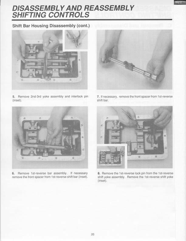
(1nsel).
DISASSEMBLY AND REASSEMBLY SHIFTING CONTROLS
Shift Bar Housing Disassembly (cont.)
r
9. Remove lhe actua1or
11. Remove 1he revetse plu:noer reta.intng plug and ga.Ske:t from 1he shift bar housing
1 O. Remove tile four interlockballs.1ha lhf'eedeten1 balls. 100 ltlrce back up liQht swnch bafls, and the 1.hree springs trom the shltc bar hou-.sing.
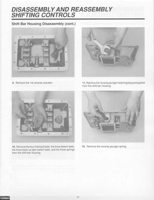
12. Remove the reverse plunger spring.
Shift Bar Housing Disassembly (cont.)
13. Remove 1he reverse s1op
15. II the nre tObe repl;ieed, remove worn pnd trom sh1t1 yOke 1n.s1:ill now p.'dandbend tabG. over top and bottom 01 yOke
164 I' necess.ary itllft bll)Cll.S and shift yokes ca.., be
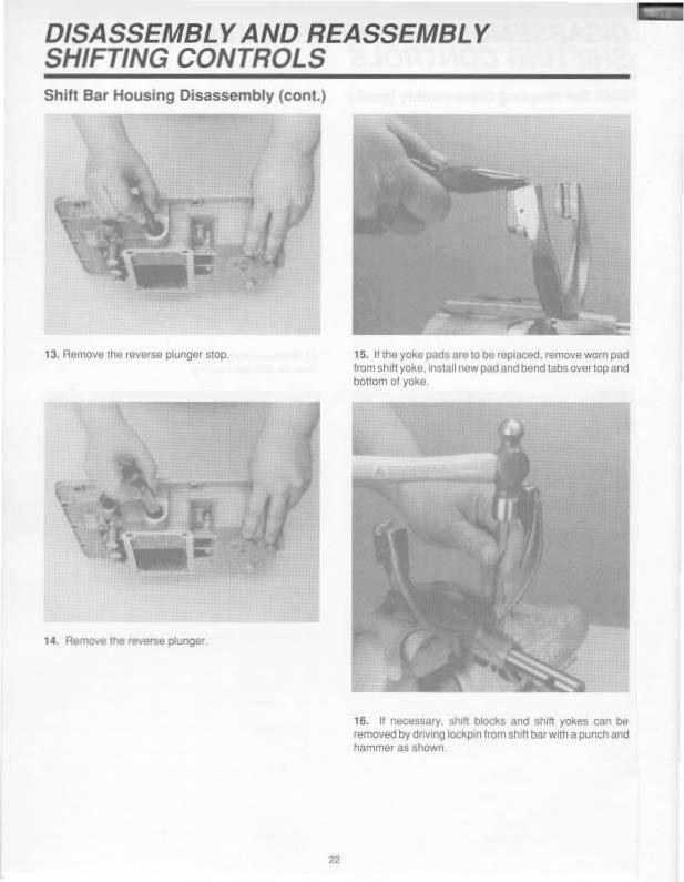
removed bydr1vi1"1Q IOCkp.n from sh f1 bar with a punch aod hammer as shown
DISASSEMBLY AND REASSEMBLY SHIFTING CONTROLS
D. Reassembly of Shift Bar Housing
1. Pillot tho shift bar housing on 1 tr side as shOwn ond 1ns11.1U 1ho rovo1so plunger.
3. I nstaD !he 1 ptungor gaske1 ancf plug Tighteo lhO reverse plunger plug 10 11101ecommended tCKq1,1e
2. 1ns1o1 .,. ,...,... - r.-i ll>d ,,,. - """""" -
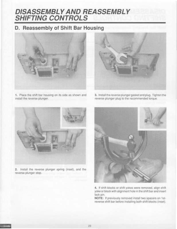
4. If shdt block$ or st 1fl yok• were removed ahgn sh 11 yoke or b6ock with 01.gnment holo 1n the shrl't bar end inaer1 klck P'" NOTE: II p11MOUsly IQl'l'IOVOd install two spacers on 1$l· teverse sh1h 1>a1 before •nstotllng both shift blocks (inse-11.
Shift Bar Housing Assembly (cont.)
s. Install intoOOck bails, deten1 balls and springs in the following seQUence; position balls in the reverse bght swrleh oore and instaJl 1s1-reversedetentspnngand ball. ?OStbOn (2) balls In adjacent cross bore and install 2nd· 3rd detent spring and ball Position (2> balls ui adjacent cross bore and install deten1 spnr.g and ball NOTE: Salls and SJ)llngs can be used lnterohangeabl)'.
6. Seal the 1st rQVQrse actuatOf In the sh1h bar housing, over 1he actuator pll/01 ptn, as shown
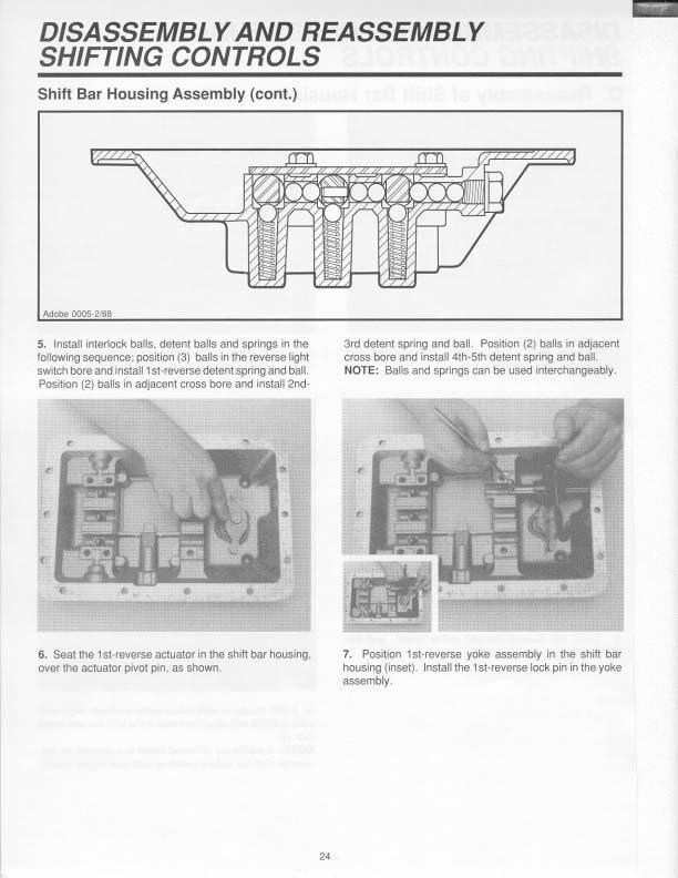
7. POStbon tst·reverse yoke assembly in dle shift bar housing (inset) Install the 1st-reverse lock pin in the yoke assembly.
DISASSEMBLY AND REASSEMBLY SHIFTING CONTROLS
Shift Bar Housing Assembly (cont.)
8. Position bat assambfy in mo hous.ng as· sembty as shown. NOTE: Position spacQrs as shOwn 1 O. Position 1he 4th· 5th yoke assembly in lhe hovslng assembly as shown.

9. ln!lalt the 2nd·3rct yoke assembly interlock pin POSlbon the 2nd-3rd yoke assembly ln the housing ass.em· bly as shown
11. Place lhe still! yokes an oou11at and Install the 1wo retainers atld lhe tout capscrews as sllO•llfl Tigh1on the e.apsaews 10100 recommenced tOtQUB. Shih 4th· Sth yoke as&&mbfy into 4tll speed pos111on.
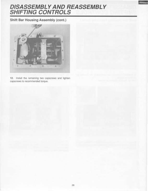
Shift Bar Housing Assembly (cont.)
12. lns1au lhe remaln1ng rwo capscrews nnd tighten capsc1&w1 10 1ooommcnded 1orque