20 minute read
Technical specifications


Tightening torque
Tightening torque in Nm for oiled or dry bolts tightened with a torque wrench.
Metric coarse screw thread, bright galvanized (fzb):
STRENGTH CLASS:
Metric coarse thread, zinc-treated (Dacromet/GEOMET):
2022-02-09
4812164101_A.pdf
ROPS - bolts
Bolt dimensions : M12 (PN 4700508063)
Strength class : 8.8
Tightening torque : 70 Nm
ROPS-bolts which are to be torque tightened must be dry.
Hydraulic system
oil-based or liquid based on saturated synthetic ester. Specification according to chapter "Maintenance – Lubricants and symbols"
2022-02-09
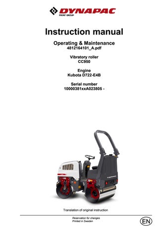
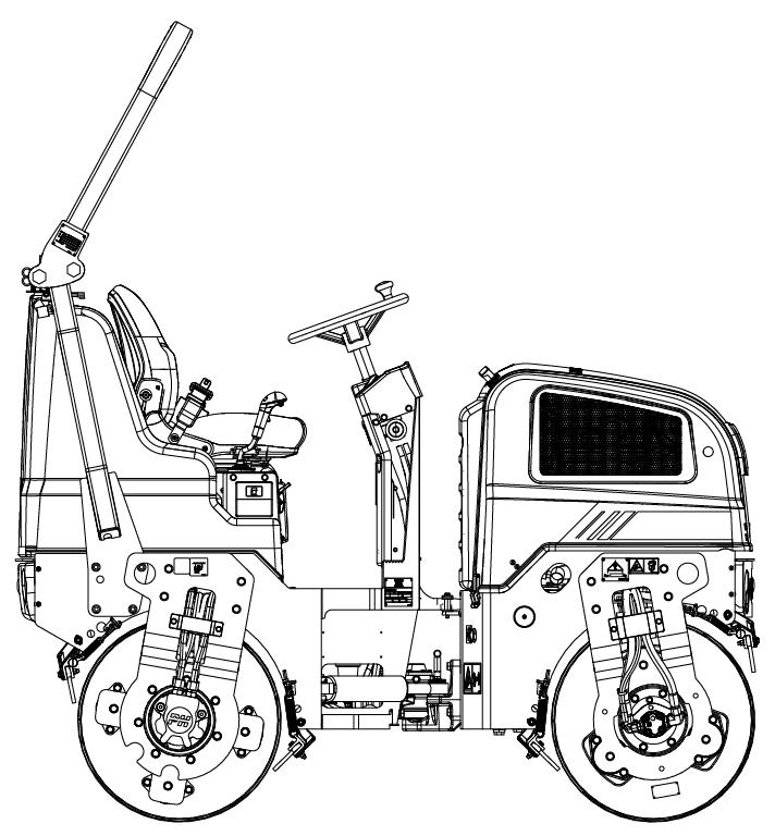
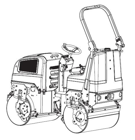
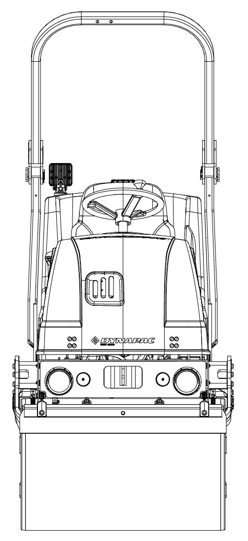
Machine description
Machine description
Diesel engine
The machine is equipped with an liquid-cooled, three cylindre, diesel engine.
Electrical system
The electrical system on the machine is controlled by relay logic. It's operated by buttons and switches.
Propulsion system/Transmission
The propulsion system is a hydrostatic system with a hydraulic pump supplying two motors connected in serial.
The motors drive the front and rear drums.
The speed of the machine is proportional to the deflection/angle of the control lever from neutral.
Brake system
The brake system consists of a service brake, secondary brake and parking brake. The service brake is hydrostatisc and is activated by moving the control lever to neutral.
Secondary/Parking brake
The secondary and parking brake system consists of spring loaded brakes in the motors. The brakes are released with hydraulic pressure and are operated with a switch on the instrument panel.
Steering system
The steering system is a hydrostatic system. The control value on the steering column distributes the flow to the control cylinder, which actuates the articulation.
The steering angle is proportional to the deflection of the steering wheel.
Seat
Different kind of seats are available. The seat always comply with at least the applicable requirements on the market where the machine is originally placed.
Seat is tested and comply with seat dimension ISO 11112, SIP ISO 5353, suspension ISO7096, seat belt ISO 6683.
ROPS
ROPS is the abbreviation for "Roll Over Protective Structure" (ISO 3471).
4812164101_A.pdf
Machine description
If any part of the cab's or the ROPS structure's protective construction displays plastic deformation or cracks, the cab or the ROPS structure must be replaced immediately.
Never perform unauthorized modifications on the ROPS structure without first having discussed the modification with Dynapac's production unit. Dynapac determines whether the modification could result in the approval according to the ROPS standards becoming invalid. Identification Product and component plates
Machine description
Machine plate
The machine plate (1) is attached to the front right side of the rear frame, beside the steering joint.
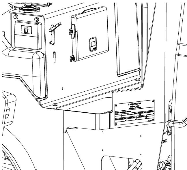
The plate specifies the manufacturers name and address, the type of machine, the PIN, Product Identification Number (serial number), operating weight, engine power and year of manufacture. CE markings and the year of manufacture may be omitted on machines supplied to markets outside the EU.
Please state the machine’s PIN when ordering spares.
Product identification number on the frame
The machine PIN (Product Identification Number) (1) is punched on the right edge of the front frame.
Engine plates
Machine description
The engine serial number (1) is punched below the starter.
Please specify the engine serial number when ordering spares. Refer also to the engine manual.

Machine description
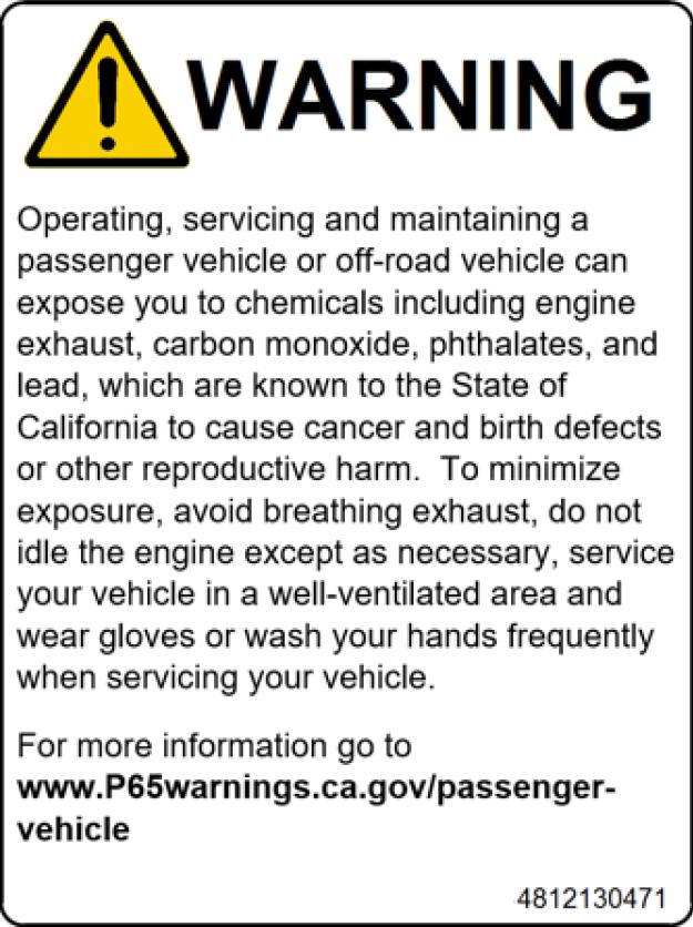
Location - decals, CALIFORNIA
Proposition 65
4812130471
Safety decals
Always make sure that all safety decals are completely legible, and remove dirt or order new decals if they have become illegible. Use the part number specified on each decal.
If a part is replaced and this part have a decal, make sure to also order the decal.
4700903422
Warning - Crush zone, articulation/drum.
Maintain a safe distance from the crush zone. (Two crush zones on machines fitted with pivotal steering)
4700903423
Warning - Rotating engine components. Keep your hands at a safe distance.
4700903424
Warning - Hot surfaces in the engine compartment. Keep your hands at a safe distance.
4700903459
Machine description
Warning - Instruction manual
The operator must read the safety, operation and maintenance instructions before operating the machine.
4700908229
Warning - Risk of crushing
The articulation must be locked when lifting. Read the instruction manual.
4811000351
Warning - Risk of tip over
If ROPS (Roll Over Protective Structure) is fitted to the roller, always wear the seat belt. Read the instruction manual.
4812125363
Warning - Locking
The articulation must be locked during transport and lifting, but be open during operation. Read the instruction manual.
4812164101_A.pdf 2022-02-09
4812130471
Warning
CALIFORNIA - Proposition 65
Machine description
Machine description
Machine description
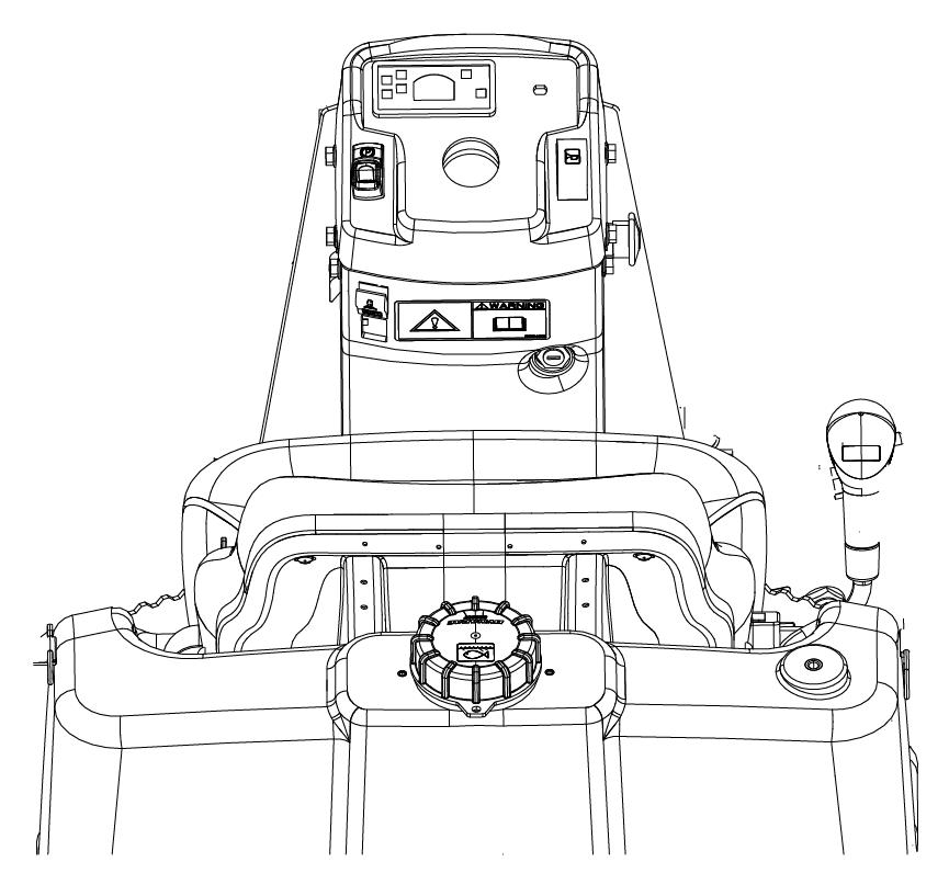
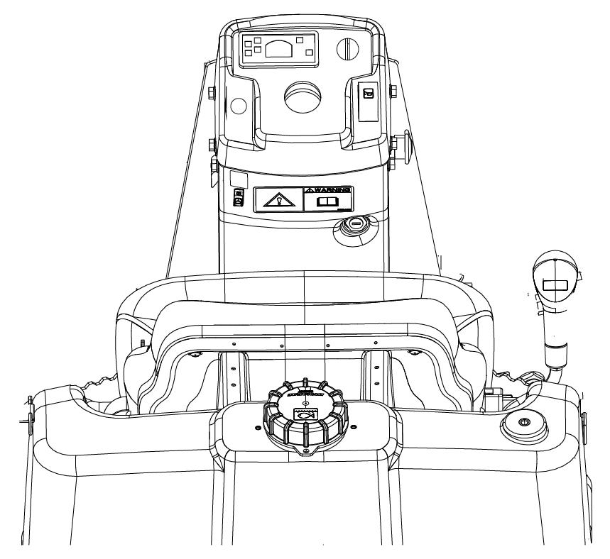
Function description
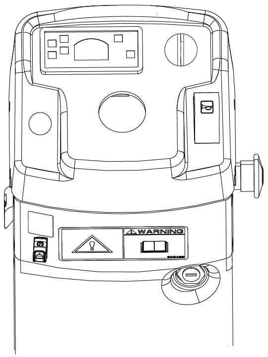
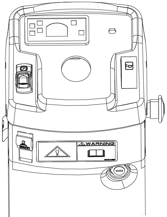
No Designation Symbol Function
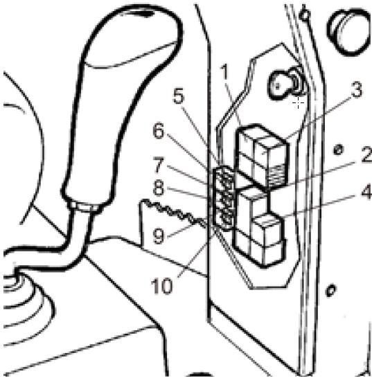
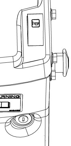
1. Fuse box (on control column)
2. Parking brake
5. Flow switch, sprinkler
6. Horn, switch
7. Emergency stop
8. Starter switch
9. Sprinkler, switch
12. Forward/Reverse lever
Contains fuses for the electrical system. See under the heading ‘Electrical system’ for a description of fuse functions.
To activate the brakes, press the top of the switch to change the position of the switch.
To release the brakes, press down the red part at the same time as the switch and change the position of the switch.
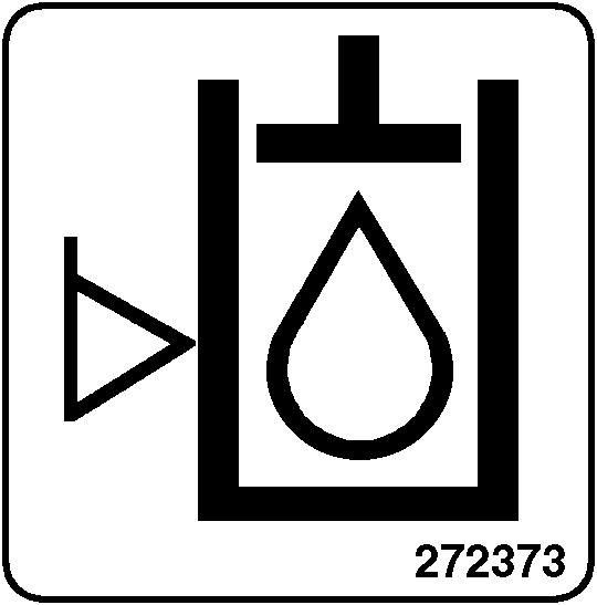
Turn the knob clockwise to switch on the water flow to the drum.
Press to sound the horn.
Brakes the roller and switches off the engine. The power supply goes off.
NOTE: The emergency stop must be deactivated when starting the machine.
The electric circuit is broken.
All instruments and electrical controls are supplied with power
Starter motor activation.
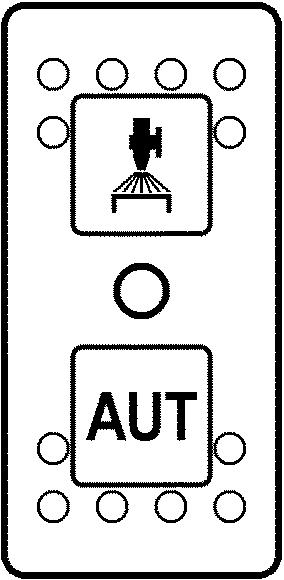
Upper position = switching on of flow of water to drum. Intermediate position = Sprinkling switched off Lower position = switching on of water to drum via forward/reverse lever.
The flow of water can be controlled by means of the sprinkler timer (24).
Watering off
AUTO Water supply to drum via forward/reverse lever in AUTO mode.
The flow of water can be controlled by means of the sprinkler timer (24).
The lever must be in neutral to start the gasoline engine. The engine cannot be started if the forward/reverse lever is in any other position.
The forward/reverse lever controls both the roller's driving direction and speed. When the lever is moved forward, the roller moves forward etc.
The roller's speed is proportional to the distance the lever is from the neutral position. The further the lever is from the neutral position, the higher the speed.
13. Vibration On/Off. Switch
15. Control, engine speed
When the switch for vibrations in the forward/reverse lever is pressed and released, the vibrations are engaged. Press the switch again to disengage the vibrations.
Pull the lever up to obtain idling speed. Move the lever down to obtain working speed.
No Designation Symbol Function
18, Fuel level
19. Parking brake warning lamp, Hydraulic oil temperature (not in use)
21. Hourmeter
24. Sprinkler timer (Optional)
Machine description
Shows the fuel level.
The light comes on when the Parking brake is activated.
Hydraulic oil temperature lamp is not valid while not in use.
Shows the number of hours the engine has run.
Stepless regulation of the water flow from 0-100%. Only functions where AUTO (13) is depressed.
2022-02-09
4812164101_A.pdf
Machine description
Electrical system
Relays and fuses on the machine
The figure shows the positions of the various fuses and relays. The table below gives their amperage and function. All fuses are flat pin fuses.
2022-02-09
Machine description
Relays and fuses on the machine
The figure shows the positions of the various fuses and relays. The table below gives their amperage and function. All fuses are flat pin fuses.
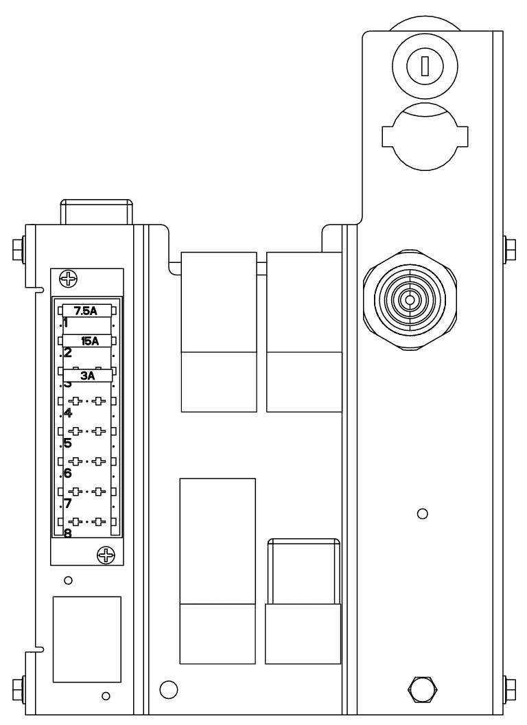
Relays
2. K2 Start, Vibration, Brake 15A
4. K20 Drive restriction relay 10A
3. K22 Cooling fan, hydraulic system (Option) 30A
1. K1 Starting 30A
Fuses
5. 7.5A Start 7,5A
6. 15A Horn, Backup alarm, Electric fan, Electric cooling of hydraulic oil 15A
7. F1.3 Start relay, Time relay, Elektric fuel pump, Stop valve, Brake valve, Vibration valve (front drum)
8. F1.4 Spare
9. F1.5 Spare
10. F1.6 Spare
11. F1.7 Spare
12. F1.8 Spare
4812164101_A.pdf
3A
Operation
Before starting
Battery isolation switch - On
Remember to carry out daily maintenance. Refer to the maintenance instructions.
The battery disconnector is located on the left side of the engine compartment.
Turn the key (1) to the On position.
The roller is now supplied with power.
The engine cover must be unlocked when operating, so that the battery can be quickly disconnected if necessary.
1
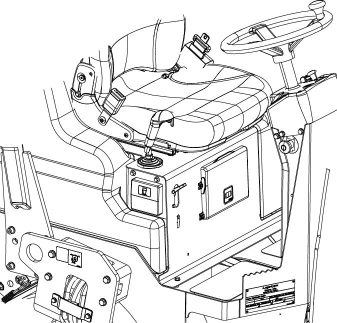
Operator’s seat - Adjusting
Adjust the operator’s seat so that the position is comfortable and so that the controls are within easy reach.
The seat can be adjusted lengthways (1).
Instruments and lamps - Checking
Make sure that the emegency stop is pulled out and the parking brake is activated. When the forward/reverse lever is in neutral, the automatic brake function is engaged.
Turn the switch (8) to position 3a.
Check that the warning lamps in the warning panel (4) come on.
Set the flow / sprinkler switch (5, 9) to the operating position and check that the system is functioning.
Make sure that the parking brake (2) is activated.
Set the knob (5) for the sprinkler in the open position and check that the drums are watered.
On machine with pressurized sprinkler system: Turn the starter switch (8) and start the sprinkler pump with the switch (9).
Check that the drums are watered.
Parking brake
Activate the parking brake (2) before leaving the machine.
The machine can be started with the parking brake (2) deactivated.
Emergency stop
The machine can only be started if the emergency stop (7) is deactivated.
Interlock
The roller is equipped with Interlock.
The diesel engine with switch off after 4 seconds if the operator gets off the seat when going forwards/backwards.
If the control is in neutral when the operator stands up a buzzer will go on until the parking brake button is activated.
If the parking brake remains inactive, the diesel engine turns off after 4 seconds.
The engine does not stop if the parking brake is activated.
The diesel engine will switch off immediately if for any reason the forward/reverse lever is moved out of neutral when the operator is not sitting down and the parking brake button has not been activated.
Sit down for all operations!
Operator position
Replace the seat belt (1) if it shows signs of wear or has been subjected to high levels of force.
Never use the forward/reverse levers as a handle when mounting or disembarking from the roller.
Check that the rubber elements (4) on the platform are intact. Worn elements will reduce comfort.
Ensure that the anti-slip (5) on the platform is in good condition. Replace where anti-slip friction is poor.

Machines with folding ROPS must always be operated with the ROPS raised and locked in position.
The interlock must always be checked before operating. To do this the operator stands up from the seat as shown in the instructions in the section Operation.

Inspect the ROPS for damages. Contact your supervisor for further actions if damages are detected.
If ROPS (Roll Over Protective Structure) is fitted to the roller, always wear the seat belt (1) provided and wear a protective helmet.
View
Before starting, make sure that the view forwards and backwards is unobstructed.
Starting
Starting the engine
Make sure that the parking brake (2) is activated. Sit down in the operator's seat and set the forward/reverse lever (12) in neutral. You cannot start the gasoline engine with the lever in any other position.
Set the RPM control (16) to idle.
For cold start: Pull out the choke (11) and turn the ignition key to position II. Check that the warning lamps on the control panel are working. Turn the ignition key (8) to the right. As soon as the engine has started, release the ignition key.
Do not run the starter motor for too long. If the engine does not start immediately, wait a minute or so before trying again.
Warm up the engine at idling speed for a few minutes, although longer if ambient temperature is below +10 C (50 F). Push in the choke as soon as possible.
When the engine is warm, check that the parking brake warning lamp (19) is still lit.
When starting and driving a machine that is cold, remember that the hydraulic fluid is also cold and that braking distances can be longer than normal until the machine reaches the working temperature.
Ensure that there is good ventilation (air extraction) if the engine is run indoors. Risk of carbon monoxide poisoning.
Driving Operating the roller
Under no circumstances is the machine to be operated from the ground. The operator must be seated at the machine during all operation.
Move the speed control (16) down to its working position.
Deactivate the parking brake (2). Be prepared that the roller can move.
Check that the steering is working correctly by turning the steering wheel once to the right and once to the left while the roller is stationary.
When compacting asphalt, remember to turn on the sprinkler system (5).
Make sure that the area in front of and behind the roller is clear.
Carefully move the forward/reverse lever (12) forwards or backwards, depending on which direction of travel is required.
Speed increases as the lever is moved away from the neutral position.
The speed should always be controlled using the forward/reverse lever and never by changing the engine speed.
Test the function of the reserve brake by activating the parking brake (2) while the roller is moving slowly forwards and backwards.
Check when operating that the warning lamps do not come on.
Interlock/Emergency stop/Parking brakeCheck
The interlock, emergency stop and parking brake must be checked daily before operating. A function check of the interlock and emergency stop requires a restart.
The interlock function is checked by the operator standing up from the seat when the roller is moving very slowly forwards/backwards. (Check in both directions). Hold the steering wheel firmly and brace yourself for a sudden stop. A buzzer goes on and after 4 seconds the engine switches off and the brakes are activated.
Check the function of the emergency stop by pressing the emergency stop when the roller is moving slowly forwards/backwards. (Check in both directions). Hold the steering wheel firmly and brace yourself for a sudden stop. The engine switches off and the brakes are activated. If malfunction is detected during emergency stop testing, replace it immediately with a new one.
Check the function of the parking brake by activating the parking brake when the roller is moving very slowly forwards/backwards. (Check in both directions). Hold the steering wheel and brace yourself for a sudden stop when the brakes are activated. The engine does not switch off.
Vibration
Manual vibration - Switching on
Vibration should not be active when the roller is stationary. This can damage both the surface and the machine.
Engage and disengage vibration using the switch (13) on the underside of the forward/reverse lever.
Always switch off vibration before the roller comes to a standstill.
2022-02-09
8 12 13 15
Braking
Service brake
When starting and driving a machine that is cold, remember that the hydraulic fluid is also cold and that braking distances can be longer than normal until the machine reaches the working temperature.
Press the switch (13) to switch off the vibration. Move the forward/reverse lever (12) to the neutral position to stop the roller.
Never leave the operator platform without activating the parking brake (2).
Reserve brake
Braking is normally activated using the forward/reverse lever. The hydrostatic transmission retards and slows the roller when the lever is moved towards the neutral position.
A disc brake in each drum motor acts as reserve brake when in motion and as a parking brake when stationary.
To brake in an emergency situation, press in the emergency stop (7), hold the steering wheel firmly and be prepared for a sudden stop.
After braking, return the forward/reverse lever to the neutral position and pull out the emergency stop (7).
Activate the parking brake (2) before leaving the machine.
Emergency stop
The emergency stop is activated by pressing the button (7).
Hold the steering wheel firmly and brace yourself for a sudden stop.
The brake is applied and the engine stops.
After an emergency stop, return the forward/reverse lever to neutral and deactivate the emergency stop by pulling out the button (7).
Switching off
Turn the engine speed control (16) back to idling. Allow the engine to idle for few minutes to cool.
Activate the parking brake (2).
Turn the starter switch (8) to the left to shut off position.
2022-02-09
Parking Chocking the drums
Never leave the operator platform without activating the parking brake.
Make sure that the roller is parked in a safe place with respect to other road users. Chock the drums if the roller is parked on sloping ground.
Keep in mind that there is a risk of freezing during the winter. Drain the water tanks and water lines. Fill antifreeze in the engine cooling system. Also see maintenance instructions.
Before using the roller again, make sure that the engine is switched off and the parking brake is activated. The brake chocks can then be removed.
Battery disconnector
Before leaving the roller at the end of the shift, switch off the battery disconnector (1) and remove the key. This will prevent battery discharging and will also make it difficult for unauthorized persons to start and operate the machine. Lock also the engine cover.
2022-02-09
Long-term parking
The following instructions should be followed when long term parking (more than one month).
These measures apply when parking for a period of up to 6 months.
Before re-commissioning the roller, the points marked with an asterisk * must be returned to the pre-storage state.
Wash the machine and touch up the paint finish to avoid rusting.
Treat exposed parts with anti-rust agent, lubricate the machine thoroughly and apply grease to unpainted surfaces.
Engine
* Refer to the manufacturer’s instructions in the engine manual that is supplied with the roller.
Battery
* Remove the battery from the machine, clean, grease the cable connectors (terminals) and trickle charge the battery once a month. The battery is otherwise maintenance free.
Air cleaner, exhaust pipe
* Cover the air cleaner (see under the heading ‘Every 50 hours of operation’ or ‘Every 500 hours of operation’) or its inlet with plastic or tape. Also cover the exhaust pipe opening. This is to avoid moisture entering the engine.
Sprinkler system
* Drain the water tank completely (see under the heading ‘Every 2000 hours of operation’). Drain all hoses, filter housings and the water pump. Remove all sprinkler nozzles (see under the heading ‘Every 10 hours of operation’).
Fuel tank
Fill the fuel tank completely full to prevent condensation.
4812164101_A.pdf
Hydraulic reservoir
Fill the hydraulic reservoir to the uppermost level mark (see under the heading ‘Every 10 hours of operation.’)
Steering cylinder, hinges, etc.
Grease the steering cylinder piston with conservation grease.
Grease the hinges on the doors to the engine compartment. Grease both ends of the forward/reverse control (bright parts) (see under the heading ‘Every 500 hours of operation’).
Engine coolant
Check that the coolant mix are within recommended levels and have a freezing temperature lower than expected lowest temperature during the storage period.
Hoods, tarpaulin
* Lower the instrument cover over the instrument panel.
* Cover the entire roller with a tarpaulin. A gap must be left between the tarpaulin and the ground.
* If possible, store the roller indoors and ideally in a building where the temperature is constant.
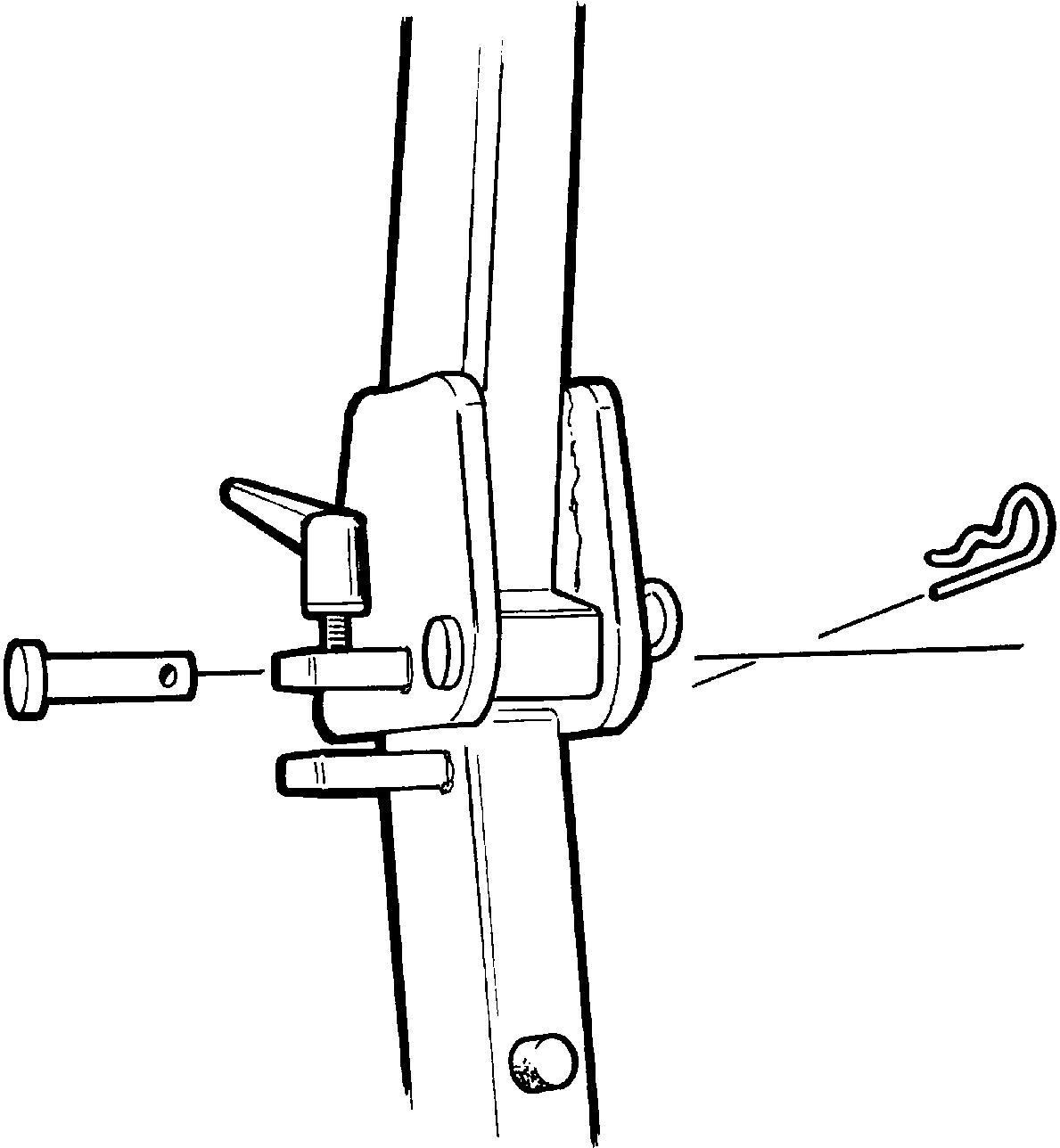
Locking the articulation
Before lifting the roller the steering joint must be locked to prevent it turning.
Turn the steering wheel to the straight ahead position. Switch off the machine. Apply the parking brake.
Raise the locking arm (1) and turn 180 degrees downward. Ensure that the cotter pin (2) is guided into its lower position correctly for locking the articulation.
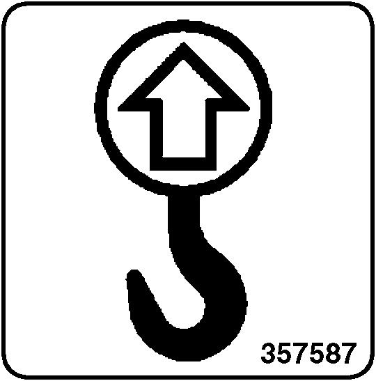
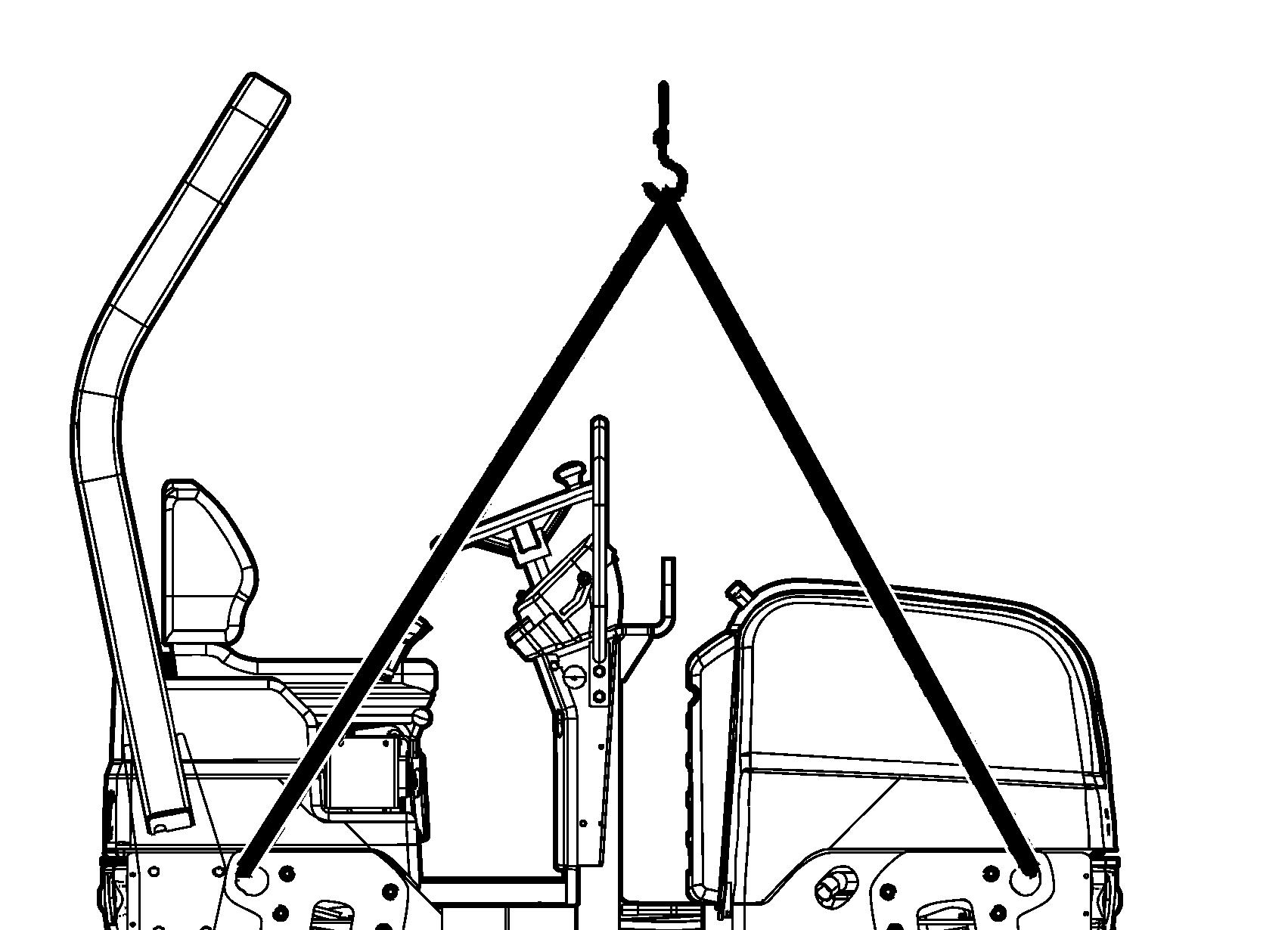
Lifting the roller
The machine’s gross weight is specified on the hoisting plate (1). Refer also to the Technical specifications.
Lifting gear such as chains, steel wires, straps, and lifting hooks must be dimensioned and used in accordance with the applicable safety regulations for lifting devices.
Stand well clear of the hoisted machine! Make sure that the lifting hooks are properly secured.

Unlocking the articulation
Remember to unlock the articulation before operating.
Raise the locking arm (1) and turn it 180 degrees upward. Check that the cotter pin (2) is guided correctly into position for unlocking the articulation.
Transport
Tie-down and secure the machine according to the Cargo Securing Certificate for the specific machine if this is avaliable and applicable.
If not, tie down and secure the machine according to the cargo securing rules that are valid for the country where the transport takes place.
Never lash over the machine’s articulated joint, nor over the machine’s operator platform.
Before securing the machine ensure that :
• the parking brake is applied and in good working condition
• the articulated joint is in closed position
• the machine is centered laterally on the platform
• the lashings are in good condition and fulfills the corresponding rules for transport securing.
Securing CC950 for loading
Securing of a double vibratory roller of model CC950 from Dynapac loaded on a trailer for transport on road and in the Baltic / North sea (sea area A/B). Direct of travel
1 - 2 = double lashings, i.e. one lashing with two parts secured to two different lashing mounts on the trailer, symmetrically located on the right and left sides.
3 = rubber friction pads
The lashings' permitted distance interval in meters (1 - 2: Double lashings, LC at least 1.6 tonnes (1600 daN)
Load carrier
Ensure that:
- When loaded, the vibratory roller is centered laterally on the platform (± 5 cm).
- The parking brake is applied and in good working condition, and the articulated joint lock is closed.
- The drum is placed on a rubber liner, so that the static friction between the surfaces is at least 0.6.
2022-02-09
- The contact surfaces must be clean, wet or dry, and free from frost, ice and snow. If there is a risk of frost, ice and/or snow the platform has to be salted.
- The lashing mounts on the load carrier have LC/MSL at least 2 tonnes.
Lashings
Ensure that:
- The lashings comprise a lashing strap or chain with a permitted load (LC/MSL) of at least 1.6 tonnes (1,600 daN) and the lashings are well pre-tensioned during the entire transport.
- Each of lashings 1-2 is either a double or two single lashings. A double lashing runs in a sling through a lashing point or around a machine part and down into two different mounts on the platform.
- Lashings in the same direction are placed in different lashing mounts on the trailer. Lashings that are pulled in opposite directions may be placed in the same lashing mount, however.
- The lashings are as short as possible.
- The lashing hooks must not lose grip if the lashings become slack.
- The lashings are protected against sharp edges and corners.
- The lashings are located symmetrically in pairs on the right and left sides.
Direct of travel
Securing
CC950 for loading (Side along the trailer)
Securing of two CC950 vibratory rollers from Dynapac loaded side by side along a trailer for transport on road and in Baltic sea (Sea area A).
1 - 2 = double lashings, i.e. one lashing with two parts secured to two different lashing mounts on the trailer. Symmetrically located on the right and left sides.
3 = wooden battens used as spacers between the rollers, kept in place by sufficient means
4 = the two rollers are tied together to one unit.
5 = rubber friction pads
The lashings' permitted distance interval in meters (1 - 2: Double lashings, LC at least 1.6 tonnes (1600 daN)
2022-02-09
Load carrier
Ensure that:
- When loaded, the vibratory roller is centered laterally on the platform (± 5 cm).
- The parking brake is applied and in good working condition, and the articulated joint lock is closed.
- The drum is placed on a rubber liner, so that the static friction between the surfaces is at least 0.6.
- The contact surfaces must be clean, wet or dry, and free from frost, ice and snow. If there is a risk of frost, ice and/or snow the platform has to be salted.
- The lashing mounts on the load carrier have LC/MSL at least 2 tonnes.
Lashings
Ensure that:
- The lashings comprise a lashing strap or chain with a permitted load (LC/MSL) of at least 1.6 tonnes (1,600 daN) and the lashings are well pre-tensioned during the entire transport.
- Each of lashings 1-3 is either a double or two single lashings. A double lashing runs in a sling through a lashing point or around a machine part and down into two different mounts on the platform.
- Lashings in the same direction are placed in different lashing mounts on the trailer. Lashings that are pulled in opposite directions may be placed in the same lashing mount, however.
- Lashing 4 ties the two rollers together to one unit. The lashing is drawn from drum to drum or from lashing eye to lashing eye on the front part as well as the rear part of the rollers.
- The lashings are as short as possible.
- The lashing hooks must not lose grip if the lashings become slack.
- The lashings are protected against sharp edges and corners.
- The lashings are located symmetrically in pairs on the right and left sides.
2022-02-09
Retractable ROPS (Optional)
The machine can be equipped with retractable ROPS.
Risk of crush injury when raising and lowering ROPS.
If the roller is equipped with a retractable ROPS, the machine must only be operated when it is lifted up and locked.
To retract the ROPS, release the tensioning screw (1), and pull out the pin (2) and stud (3). Do the same on both sides. Lower the ROPS backwards if there is space.
Remember to dismantle the rotating warning light before lowering the ROPS.
After lowering the ROPS, replace the pin and stud.
To lift the ROPS proceed in the reserve order.
Always make sure the ROPS is locked in raised position before operation.
Grease the tensioning screw (1) and stud (3) periodically.
Towing/Recovering
The roller can be moved up to 300 meters (330 yards) using the instructions below.
Towing the roller
A towing bar must be used when towing, as the roller has no brakes and can only be slowed and stopped by the vehicle towing the roller.
The roller must be towed slowly, max. 3 km/h (2 mph) and for short distances only, max. 300 m (1000 ft).
When towing/recovering a machine, the towing device must be connected to both lifting holes. Pulling forces shall act longitudinally on the machine as illustrated. Max total towing force 50.8 kN (11,430 lbf), 25.4 kN (5,715 lbf) per fork.
Reset the steps taken for towing as described in the towing instructions on the previous page.
Switch off the diesel engine and activate the parking brake. Chock the drum to prevent the roller from moving when the brakes are disengaged.
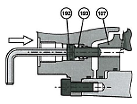
The brakes in each propulsion motor must be mechanically released, as described below, before the roller is towed.

Releasing the brake
1. Remove the 2 plugs (191).
2. Press the screws (192) inwards to compress the springs (193) so that the screw reaches the brake (107) inner thread.
3. Tighten the two screws (192) alternately a little at a time so that the brake piston (107) loose (screw approximately 2 turns).
Tightening the screws (192) too hard can damage the inner mechanism
The machine should be started with reactivated brake.
Restored brake
Undo the two screws (192) alternately, and then insert the plugs (191).
Tightening torque
Screws (192)
Plugs (191)
Operating instructions - Summary
1. Follow the SAFETY INSTRUCTIONS specified in the Safety Manual.
2. Make sure that all instructions in the MAINTENANCE section are followed.
3. Set the Emergency stop to its pulled-out position.
4. Move the forward/reverse lever to the NEUTRAL position.
5. Set the engine speed control to idle.
6. Start the engine and allow it to warm up.
7. Set the engine speed control to the operating position and make sure that the parking brake is deactivated.
8. Drive the roller. Operate the forward/reverse lever with care.
9. Test the brakes. Remember that the braking distance will be longer if the roller is cold.
10. Use vibration only when the roller is in motion.
11. Check that the drums are thoroughly watered when watering is required.
12. IN AN EMERGENCY:
- Press the EMERGENCY STOP
- Hold the steering wheel firmly.
- Brace yourself for a sudden stop.
13. Parking: - Switch off the machine and chock the drums.
14. When lifting: - Refer to the relevant section in the Instruction Manual.
15. When towing: - Refer to the relevant section in the Instruction Manual.
16. When transporting: - Refer to the relevant section in the Instruction Manual.
17. When recovering - Refer to the relevant section in the Instruction Manual.
2022-02-09
4812164101_A.pdf