16 minute read
Regeneration System


Regeneration system (Emission Control)
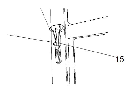
After Treatment Screen
In this screen you will find urea tank level, warning lamps and engine oil temperature.
Make sure that the Urea tank is full during operation
It´s recommended to fill or drain the tank with the system off.
If the Urea tank is completely empty you mayhave error codes related to the after treatment system in the display due to invalid measurements. To clear the error code the tank must be filled and perform a key cycle, start the engine and run it in high idle for 5 minutes.
Diesel Exhaust Fluid (DEF) Lamps
DEF Lamp
Illuminates when DEF level is low, and flashes when the DEF falls below a very low level. Operator should refill the DEF tank with DEF.
DEF Lamp With Check Engine Lamp
Illuminates when the DEF level is critically low. If the tank is not refilled immediately, power will be reduced. Operator should refill the DEF tank with DEF. Normal engine power will be restored after the DEF tank is refilled.
Flashing DEF Lamp With Check Engine Lamp
Illuminates when the DEF level is near zero. If the tank is not refilled immediately, power will be further reduced. Operator should refill the DEF tank with DEF. Normal engine power will be restored after the DEF tank is refilled.
Flashing DEF Lamp With Stop Engine Lamp
Illuminates when the DEF gauge has read zero for 30 minutes. Power will be limited to idle. Operator should stop the equipment when it is safe to do so, and refill the DEF tank. Normal engine power will be restored after the DEF tank is refilled.
Exhaust System Cleaning Lamps
High Exhaust System Temperature (HEST) Lamp
May illuminate due to higher-than normal exhaust temperature during Exhaust System Cleaning. Operator should ensure that the exhaust pipe outlet is not directed at any flammable or combustible surfaces.
Exhaust System Cleaning Lamp
Illuminates when the exhaust system is unable to complete an automatic Exhaust System Cleaning event. Operator should ensure the Exhaust System Cleaning Switch is not in the “STOP” position and continue working until there is an opportunity, such as at the end of the work day or shift, to complete a stationary Exhaust System Cleaning.
Exhaust System Cleaning Lamp With Check Engine Lamp
If an Exhaust System Cleaning is not performed in a timely manner after the Exhaust System Cleaning Lamp is illuminated, the Check Engine Lamp will illuminate and engine power will be significantly reduced. Park the equipment when safe to do so, and press the Exhaust System Cleaning Start Switch. Once the cleaning is complete, full engine power will be restored.
Exhaust System Cleaning Lamp
Flashes when a stationary Exhaust System Cleaning event is initiated using the Exhaust System Cleaning Start Switch. This lamp will continue to flash until the stationary cleaning event is complete. Once the lamp turns off, the operator can resume normal work activity.
Exhaust System Cleaning Stop Lamp
Illuminates when the Exhaust System Cleaning Switch is in the “STOP” position, preventing a cleaning event. This switch should be used only when high exhaust temperatures present a hazard. Excessive use of the Exhaust System Cleaning Switch in the “STOP” position will result in the need for more frequent stationary exhaust cleaning events.
Regeneration System
Exhaust System Cleaning Switch
Exhaust System Cleaning Enabled
The switch remains in the standard mid-position during normal operations. This means Exhaust System Cleaning is enabled and allows the exhaust system to clear any build-up by initiating automatic cleaning. Exhaust System Cleaning initiated automatically by a preset timer at 20hour intervals and takes around 15-30 minutes to complete. No operator action is required and the equipment continues to work as normal during the cleaning.
The HEST lamp may illuminate during cleaning to indicate higher than normal exhaust temperatures and safety considerations apply.
Start Exhaust System Cleaning
Pressing the switch into the top position starts a manual (parked) Exhaust System Cleaning. This is required on infrequent occasions due to very unusual duty cycle conditions. A manual (parked) Exhaust System Cleaning may be needed when the Exhaust System Cleaning Lamp illuminates. When the Start Switch is pressed, cleaning begins and this is confirmed by the Exhaust System Cleaning Lamp flashing. The HEST lamp mayilluminate during the manual (parked) Exhaust System Cleaning to indicate higher than normal exhaust temperatures and safety considerations apply. The switch returns to the standard Mid-Position after pressing the manual (parked) Exhaust System cleaning.
Stop Exhaust System Cleaning Function
Pressing the switch into the bottom position prevents Exhaust System Cleaning from occurring. Stopping the Exhaust System Cleaning function is required only for safety reasons to avoid higher than normal exhaust temperatures. When the switch is pressed the Exhaust System Cleaning STOP Lamp illuminates to indicate Exhaust System Cleaning is disabled. The switch remains engaged in this position until pressed back to the standard mid-position to restore the automatic Exhaust System Cleaning function. Exhaust System Cleaning should not be left disabled for long periods of time as this results in the need for a manual (parked) Exhaust System Cleaning.

No. DESIGNATION
Instruments and controls - Cab
SYMBOL FUNCTION
1 Automatic Climate Control - Air conditioning automatic control (see A/C operation for detail)
2 Front wiper, intermittent - Intermittent function for front wiper
3 Front wiper switch
Press to operate the front windshield wiper.
4 Rear wiper switch Press to operate the rear windshield wiper.
5 Front and rear windshield washers switch
6 Asymmetric front wiper switch
7 Asymmetric rear wiper switch
8 Asymmetric side windshield washers switch
Press the top to activate the front washers. Press the bottom to activate the rear washers.
Press to operate the front side windshield wiper.
Press to operate the rear side windshield wiper.
Press the top to activate the front side washers. Press the bottom to activate the rear side washers.
9 Fuse box Contains fuses from the electric system in the cab.
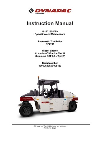
10 Hammer for emergency exit
If it is necessary to leave the cab during an emergency, release the hammer and break the right side windows.
11 Defroster nozzle - Turn the defroster nozzle to direct the air flow.
Instruments/controls - Cab 2018-02-19
A/C – System operation
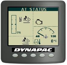
Power/Enter
By feeding the panel with 24VDC, the screen will be on, indicating that the product is in standby mode. Press to turn on the A/C, it will show the software version and then the temperature. To return to standbymode you must press the button for 3s.
Set point Up/Down
Set point is the desired temperature inside the vehicle. To set it up press or . The set point temperature will flash on the display; press until reaches desired temperature.
Display
The display shows set point value, bar graph evaporator speed, active function and other information. It also serves to allow the operator to view the coil and return temperature, as well as the parameters. It also serves to alert when there is some system flaws.
Operation Mode
To change the operation mode, press the button (operation mode), select the desired mode:
The controller has 4 operation modes that are:
- Only ventilation
- Only cooling
- Only heating
- Automatic mode
Press the button to confirm or wait a few seconds to cancel.
Ventilation
The controller has two ventilation modes: manual and automatic ventilation.
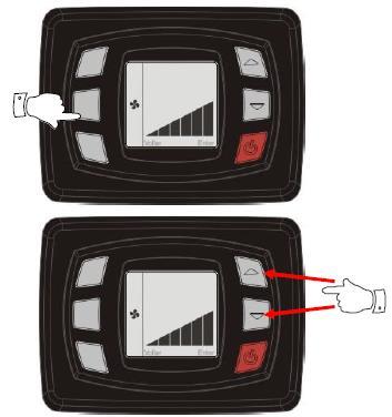
Manual ventilation
The manual ventilation has three speeds. When some function (cooling, heating or automatic mode) is active, the ventilation function is always on. To change the fan speed, press the key (Ventilation mode) and after set the desired speed with the keys or After press the key to confirm or wait a few seconds and the speed will be saved
Operation - Before starting Daily maintenance
Before startingyourwork shiftand operatingthe equipment, make sure the daily maintenance was carried out. For further information, refer to the maintenance section in this manual.
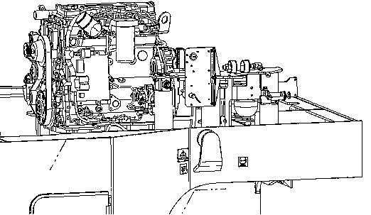
Main switch
Check if the master switch is on. The master switch is located in the electric device compartment (1) on the right side of the machine.
After the daily use of the roller, the master switch shall be turned off. It prevents the machine to be turned on accidentally and protects the electronic devices.
If the main battery switch is closed, the engine hood shall be opened during the operation to make it possible to reach in an emergency.
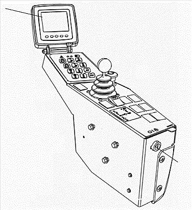
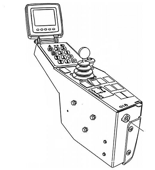
The control and operation unit
The control and operation unit has three adjustment options: transverse travel, rotation and steering column angle.
For transverse travel, raise the inner lever (1). The transverse travel brake will be released.
For rotation, raise the outer lever (2). Make sure the control unit is in the correct position before operating the machine.
For steering column angle, release the locking lever (3). Fix it again in the new position.
To adjust the operator's seat, refer to the next section.


Perform all the control and operation unit adjustments when the machine is stationary.
Before startingyourwork shiftand operatingthe machine, make sure the seat and the steering column are locked and never release the side travel if you are on a slope.
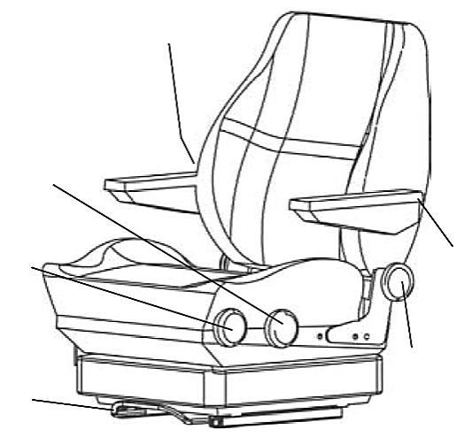
Standard operator's seat - adjustment
Adjust the operator's seat so all the controls are within easy reach and the machine operation is comfortable.
(1) Length adjustment.
(2) Weight adjustment.
(3) Back support adjustment.
(4) Seat belt.
ALWAYS make sure the seat is locked before starting the operation.
Always use the seat belt (4).
Comfort operator's seat (option) - adjustment
Adjust the operator's seat so all the controls are within easy reach and the machine operation is comfortable.
(1) Length adjustment.
(2) Height adjustment.
(3) Seat-cushion inclination.
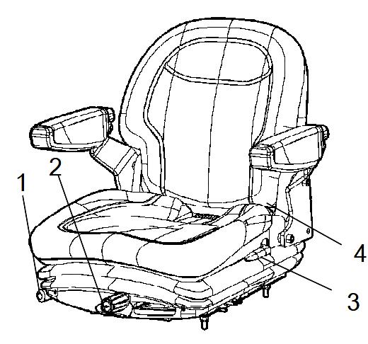
(4) Back support inclination.
(5) Armrest inclination.
(6) Lumbar support adjustment.
(7) Seat belt.
View
Before starting the engine, make sure that the view around the machine is unobstructed.
All the cab windows shall be clean and the rear view mirrors adjusted for a good rear view.
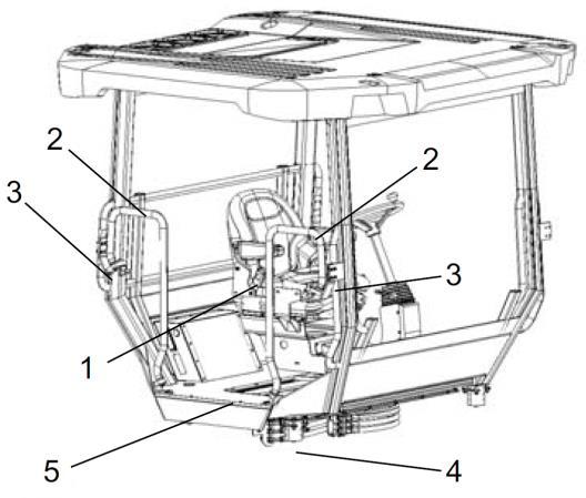
Operator position
If a ROPS (Roll Over Protective Structure) or a cab is fitted to the roller, always use the seat belt (1) and wear a protective helmet.
Always replace the seat belt for a new one if the previous show signs of wear or has been subjected to a huge impact.
The safety railings (2) around the operator's station are adjustable both in the inner and outer positions. Retract them when driving close to walls or other side obstacles.
Release the locking knob (3) and adjust and lock the railings in the desired position.
Make sure the anti-slip protections (4) of the platform are in good condition and replace them for new ones if they are worn.
If the machine is fitted with a cab, make sure the door is always closed when in motion.
Interlock
The roller is equipped with Interlock.
The Diesel engine turns off after 4 seconds if the operator leaves the seat when the machine is moving forward/backward. If the machine is in neutral position when the operator leaves the seat, a horn is sound until the parking brake is activated.
If the parking brake is activated, the Diesel engine will not stop, but the engine will be automatically turned off if, by any reasons, the transmission is not in the neutral position when the operator is not seated in his place.
Sit down for all operations!
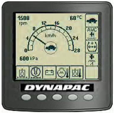
Starting Screen - Control
Sit down for all operations.
Turn the ignition key (1) to the position I and the initial screen is shown in the Control panel (2).
Check if the voltmeter (3) appoints at least 24 volt and if the fuel (4) and water (5) levels show a percentage value.

The hourmeter (6) records and shows the total quantity of the engine working hours.
Starting the engine
Make sure the emergencystop system (2) is off (upper position) and the parking brake is on.
The forward/reverse lever (1) shall be in the neutral position. The Diesel engine cannot be started if the lever is not in this position.
When sitting on the operator's seat, turn the ignition key (3) to the right (the first position I) and then to the start position. Release the switch as soon as the engine starts.
Do not try to run the start engine for too long (max. 30 seconds). If it does not work, wait 60 seconds to try again.
Let the engine idle for a few minutes or more if the environment temperature is below 50 F (10º C).
When the engine is running indoors, make sure if there is proper ventilation to extract the exhaust gases.
Operation
Display and button set
The parking brake symbol is shown when the parking brake is activated.
= Low speed.
= Automatic water control (AWC). The sprinkling is activated when the forward/backward lever is in the neutral position.
= Tire pressure.
= Sprinkler activation for edge cutter.
= High/low speed mode (in the center of the screen).
= Alarm display, see the table below for information.
Alarm descriptions
SYMBOL DESCRIPTION FUNCTION
Warning lamp, hydraulic oil filter
If the lamp is lit with the engine in maximum rpm, it shall be necessary to replace the hydraulic oil filter.
Warning lamp, air filter
Warning lamp, battery charging
Warning lamp, engine temperature
Warning lamp, hydraulic oil temperature
If the lamp is lit with the engine in maximum rpm, it shall be necessary to clean or replace the air filter.
If the lamp is lit with the engine running, the alternator is not charging. Stop the engine and find the fault.
If the lamp is lit it means the engine is too hot. Stop IMMEDIATELY the engine and find the fault. Refer to the engine manual.
If the lamp is lit it means the hydraulic oil is too hot. Do not operate the roller. Cool the oil making the engine run in idle and locate the fault.
Operating the roller
Under no circumstances the machine shall be operated away from the ground. The operator shall be seated inside the machine during the operation.

Make sure the areas at the front and behind the machine are free.
1. Select the maximum gear the machine will operate. To activate the operation speed, use the throttle on the right side of the steering column.
2. Make sure the steering is working normally by turning the steering wheel to the left and to the right once with the roller stationary.
3. When compacting asphalts, do not forget to activate the sprinkler system (1) or (2).
Release the parking brake button (5) by sliding the red lock on the button backwards and changing the lever position. Remember that the machine can roll if you are on a slope.
4. Activate the low speed (3).
5. Move the forward/backward lever (4) carefully to any direction you desire.
6. Increase or decrease the machine speed using the throttle control.
Make sure the parking brake (5) is working correctly by activating it and moving the forward/backward lever(4)totheForRposition. Keep the brake test button pressed. This way, when you throttle the machine, it will not move.
Edge cutter (option)
To activate the edge cutter, the machine must be in low speed.
When the side panel button (1) is pressed with the machine in low speed, a hydraulic piston lowers down the edge cutter to the ground
The tool can also be lifted if the machine is in the transport position.
A bypass valve prevents the hydraulic system being overloaded.
To prevent asphalt sticking to the edge cutter, the operator shall use a separate sprinkler system. It is operated by a switch (2). The water is supplied on the main tank and it is the same used in the standard sprinkler system.
Tire pressure adjustment (option)
The operator can vary the pressure during the operation with the tire air pressure control. It can be variable adjusted with the keys (2) and (3) on the keypad, within the interval from 240 kPa to 830 kPa (35 to 120 PSI) and can be reduced with the key (3). The tire pressure level is shown in the lower left corner, on the Display (1).
When the tire pressure is at the maximum level (830 kPa) or at the minimum level (240 kPa), it will not be possible to increase/decrease the pressure.
Coconut mats (option)
To apply the coconut mats (1) on the wheels, follow the instructions below:
- Hold and lift the handle in the middle of the scraper holder (2).
- Make sure the lock pin (4) releases properly from the locking hook (3) and allow the scraper to rest against the tires in the working position.
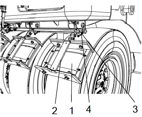
To release the coconut mats:
- Hold and lift the handle in the middle of the scraper holder (2).
- Make sure the lock pin (4) fits well in the locking hook (3).
Ballast box

Water and wet sand ballast
Remove the top covers (1) and side upper covers (3) and fill with water and sand through this opening.
Keep the side lower covers (2) closed during the water filling. Do not remove the draining plugs (4) because the water may leak when the ballast is filled with it.
Fill the ballast box, when necessary, with gravel, sand and steel.
The water shall be added when it is filled with sand, so it can fill all the spaces between the ballast.
When using the roller with mixed ballast, start using the steel objects available, and then add the requisite amount of sand and water.
Distribute the ballast evenly.
Operation
Removable steel ballasts
The CP2100/CP2100W roller uses an innovative and patented system of steel ballasts, which can be removed and installed easily and quickly:
1. With the ballast box drained (without water and/or sand), remove four side covers (1) from the ballast box.

2. Unscrew the nuts and counternuts (2) and four lower bolts (3) of the bedplate in the steel ballasts. Remove the bedplate (4) off the ballasts assembly.
3. Install or remove the ballasts, according to the necessity, using the forks from a standard forklift. The ballasts grooves (5) were projected so the forklift forks fit perfectlyand to easy their removal, installation and transport

4. After installing or removing the ballasts in the box, mount the bedplate, performing the reversal steps used to remove them.
Distribute the steel ballast evenly in the box.

Operation
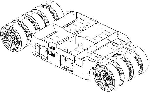
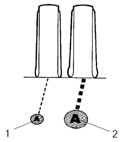
Ground pressure (driving)
The tire contact surface can be changed by means of tire pressure.
The high pressure on the tires provides a smaller contact surface (1) and the low pressure on the tire provides a larger contact surface (2).
The contact surface with the ground is very important for the compaction result. The total weight divided by the quantity of tires provides the correct pressure for the wheel, according to the following table.
Ground pressure
Operation
Low tire pressure – 240 kPa (34,8 PSI)
The lower the tires pressure, the lower the pressure on the contact surface, due to the larger surface area.
Normal tire pressure – 480 kPa (69,6 PSI)
Used for degradation session.
High tire pressure – 830 kPa (120,4 PSI)
The higher the tires pressure, the higher the pressure on the contact surface, due to the smaller surface area.
Interlock/Emergency Stop/Parking Brake
The interlock, emergency stop and parking brake shall be checked daily before starting the machine. To check if the emergency stop and interlock are working correctly, it is necessary to turn on and off the machine.
To check if the Interlock works correctly, the operator shall rise from the seat with the roller moving forwards and backwards (perform the test in both ways). The operator must hold the steering wheel firmly and be ready for a sudden stop. The alarm will be activated and after 4 seconds the engine will turn off and the brakes will be activated.
To check if the emergency stop works correctly, the operator shall press the corresponding button with the roller moving forwards and backwards (perform the test in both ways). Next, the operator must hold the steering wheel firmly and be ready for a sudden stop. The engine will be turned off and the brakes will be activated.
To check if the parking brake works correctly, it shall be activated with the roller moving forwards and backwards (perform the test in both ways). The operator shall hold the steering wheel and be ready for a sudden stop when it is activated. The engine does not turn off.
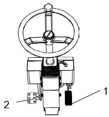
Normal braking
Release the throttle control (1) and press the brake pedal (2).
Emergency braking
The brake pedal is normally used to brake.


For emergency braking, press the emergency stop button (1), hold the steering wheel and be ready for a sudden stop. The engine stops.
The Diesel engine will be turned off and it must be turned on again, if necessary.
When starting the engine after an emergency stop, the forward/backward lever shall be in the neutral position and the parking brake shall be on.
Turning off the engine
Allow the engine to cool down in low idle for a few minutes.
Check if the Display (1) shows any indication of faults. Turn off all the lights and other electric functions.
Press the parking brake switch (3).
Turn the ignition key (2) to the left to turn it off.
Fit and fix the cover of the instruments panel over the screen and the upper part of the control box (on rollers without cab).
Chocking the wheels
Never leave the roller and let it with the engine running unless the parking brake is activated.
Make sure the machine is parked in a safe area, without traffic. Chock the wheels when parking on slopes.
In extremely cold weather, some components may freeze. Drain the water tanks and pipings.
Master switch
At the end of the working shift, turn off the battery master switch (1) and remove the handle.
This will prevent the battery discharging and will also make it difficult to start and drive the machine if unauthorized people try to use it. Close and lock the maintenance covers and doors.
Long-term storage
For long-term storage (more than a month) follow the instructions below:
These measures are valid for storage for a period of up to 6 months.

Before starting the machine again, the points stated below shall be performed before parking and store the roller.
Wash the machine and touch up the painting finishing to prevent rusting. Use anti-rust agents on the exposed parts and lubricate carefully the machine, besides applying grease to unpainted surfaces.
Engine
Refer to the manufacturer information in the engine instruction manual supplied with the roller.
Battery
Remove the batteries from the roller, clean their outside parts and recharge them once a month.
Air cleaner, exhaust pipe
Close the air tube (refer to the sections "Every 50 Hours of Operation" and "Every 1,000 Hours of Operation") or the respective intake opening with plastic or tape. Also cover the exhaust pipe opening with sealing material to avoid moisture entering in the engine.
Water distribution system
Drain all the water in the water tank and all the hoses. Also drain the filter housing and the water pump and remove all the sprinkler nozzles.
Refer to the Maintenance section to obtain further information about water draining.
Fuel tank
Fill the fuel tank completely to prevent condensation.