13 minute read
Instruction Manual


4812314581EN
Operation and Maintenance
Pneumatic Tire Roller
CP2700
Diesel Engine
Cummins QSB 4.5 – Tier III
Cummins QSF 3.8 - Tier IV
Serial number
Introduction
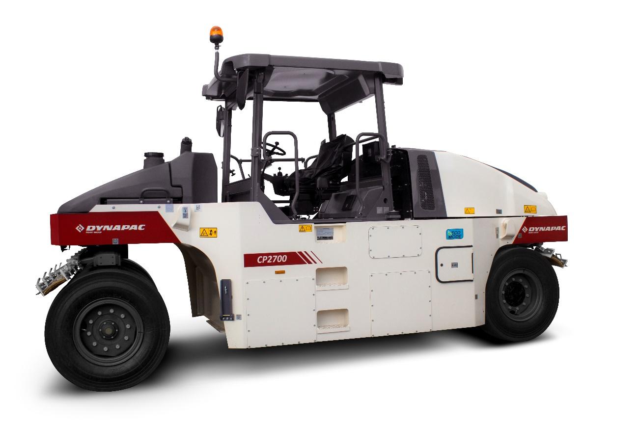
Dynapac CP2700
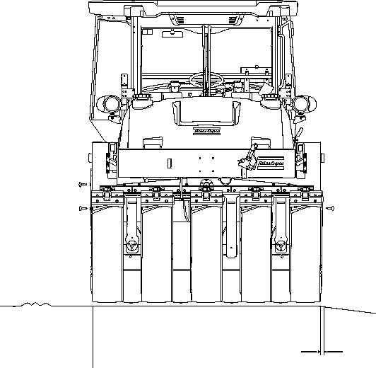
Dynapac CP2700 is a 27 tonnes rubber wheel roller, with 5,905 ft (2,300 mm) width.
It has five direction front wheels and four back wheels. The hydrostatic drivers, the flexible ballast solution and a wide range of option equipment indicate that the machine has different settings available. CP2700 is mainly used together with other asphalt rollers to seal surfaces. Thanks to its weight, it also serves as a roller for other types of ground
Warning symbols
WARNING! Damage to the machine or its parts.
CAUTION! Risk of death or injures.
Safety information
The Safety Manual delivered with the machine shall be read by the operator. Always follows the safety instructions and keep the Manual inside the machine.
It is recommended to at least train the operators on daily handling and maintenance of the machine, according to the Instruction Manual. Passengers are not allowed on the machine, and the operator must be on the seat whenever he operates the equipment.
Read throughout the manual before starting the machine and before performing any maintenance.
Request immediately new manuals if the old ones are lost, damaged or become illegible.
Make sure there is a good vent (air exhaust) when the engine is turned on in closed facilities.
General Information
This manual contains instructions to operate and perform the maintenance of the machine.
The machine's maintenance shall be made correctly in order to obtain the maximum performance and the equipment shall also be kept clean, so leakage, loosen bolts and connections can be found as soon as possible.
Perform a daily inspection in the machine before starting, so you can find possible leakage or other failures.
Verify the machine's floor. Leakages are easier detected on the floor than on the equipment itself.
THINK ABOUT THE ENVIRONMENT! Do not dispose oil, fuel or other hazard substances to the environment. Always dispose correctly used filters, draining oil and fuel residues.
This manual contains instructions for periodic maintenance, which is usually performed by the operator.
Other engine instructions can be found at the manufacturer's manual.
CE Marking and Statement of Compliance (APPLIED TO MACHINES SOLD WITHIN THE EUROPEAN COMMUNITY)
This machine has a CE Marking. It shows that at its delivery, it meets all the applicable health and safety basic directives, according to 2006/42/EC Machinery Directive, besides attending other directives applicable on machinery.
Following the machine there is a "Statement of Compliance" specifying the directive and supplement applicable, as well as the harmonized norms and other regulations relevant to the case.
Safety - General instructions
(you must also read the Safety Manual)
1. Read and understand this Manual before starting and operating the machine. The operator must be familiar with the equipment contents before operating it.
2. Observe and follow all the Maintenance Section instructions.
3. Only experienced/trained operators are allowed to operate the machine. NEVER allow the presence of passengers and ALWAYS remain seated while operating the equipment.
4. Do not operate the equipment if adjustment or repairs are necessary.
5. Use ladders and rails to enter and leave the cab. NEVER enter or leave the machine while it is moving.
6. The ROPS (Roll Over Protective Structure) should always be used when the machine is operated on unsafe ground. Always use the seat belt when the ROPS is on.
7. Use the first gear on sharp turns.
8. Avoid driving close to cliffs or sharp side slopes. Operate the machine on first gear and always check the brakes.
9. When driving close to edges or holes, make sure at least 2/3 of the wheels are on the previously compacted materials.
10. Make sure there are no obstacles over your head during the travel. Always look up and down during the travel. Make sure there are no obstacles in the direction of travel - on the ground, in front or behind the roller.
11. Drive particularly carefully on uneven ground.
12. Follow all the safety rules and use the protection equipment proper to the work to be performed.
13. Keep the roller clean. Clean immediately dirt, oil and grease accumulated on the operator platform. Keep all the signs, lanterns, headlights and decals clean, visible and legible.
14. Observe the following safety measures before refueling:
- Turn off the engine;
- Do not smoke;
- Do not allow sparks or flame next to the equipment;
- To avoid sparks, ground the filling nozzle.
15. Before performing any maintenance operation, chock the roller wheels and apply the emergency/parking brakes.
16. Hearing protection is recommended if the machine's noise level exceeds 85 dB (A). The noise level can vary depending on the work the machine performs.
17. Do not make any changes on the machine, under the risk of affecting the personal safety as well the equipment's. Any change on the machine demands a previous written approval by DYNAPAC.
18. Avoid using the machine before the hydraulic oil reaches the normal operating temperature. The braking distance may be longer than normal if the oil is cold. Refer to the operation instructions on "Stop", in the "Operation" section.
Safety - General instructions
19. For your own protection, always wear:
- Helmet;
- Working boots with steel toecaps;
- Ear protectors;
- Reflecting clothing;
- Working gloves.
20. If there is a cab in the machine, operate it always with the doors closed and with the seat belt.
Safety - When operating
Avoid people entering at the danger area, that is, at a distance of at least 23 ft (7 m) in all the directions from the machine operating. The operator can allow one person to be at the danger area, but in this case, care must be taken and the machine can only be operated when this person is in a visible place or with clear indication of where he/she is.
Operating on slopes
The machine must never be operated from the outside of the cab. The operator shall be seated when operating.
Slopes
This angle was measured on a flat, hard surface and with the machine in a stationary position.
The steering angle is zero, the tires pressure is normal and all the tanks are full.
Always remember that loosen ground, the steering of the machine, different tire pressures, the operation speed and the gravity center raising may cause the machine to turn, even on slopes smaller than the ones stated here.
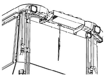
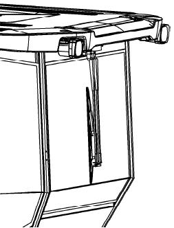
If you need to leave the cab in emergency situations, take off the hammer at the rear pillar on the right and break the opening windows that are also on the right.
It is recommended that ROPS (Roll Over Protective Structure) is always used when driving on slopes or unsafe ground.
Whenever possible, avoid driving across slopes. On slopes, drive straight up and down.
The speed must always be slow when operating on slopes.
Always operate the machine with the doors closed and with the seat belt.
>5% (2.8°) v < max. speed. (9.3 mph or 15 km/h).
Transport on steep ground
During the transport on steep ground (slope >5%), be careful to not exceed the roller's maximum speed.
Take your foot off the throttle pedal and use the engine brake system. Also use the main brake if the speed keeps increasing.
Selecting the low speed will increase the engine brake system efficacy and also the life of the braking system.
Operation and transport on steep ground
Always drive the machine in slow speed when operating or during transport on steep ground.
(>15%).
To drive or stop the machine, the rear wheels shall always be towards the slope, that is, the roller shall go up normally and shall go down in reverse.
>15% (8.5°)
Low speed (up to 4.7 mph or 7.5 km/h)
Make sure there are no obstacles both in front or behind your work area.
Driving near edges
When driving close to edges or holes, make sure that at least ¼ of the tires is on the compacted ground.
At least 1/4
Safety - Option items
Air conditioning
The system contains pressurized refrigerant. It is forbidden to release refrigerant to the atmosphere.
The maintenance of the air conditioning system shall be carried out only by trained people and with the proper tools and equipment.
The air conditioning system is pressurized. The incorrect handling can result in serious personal injury. Do not loose or disconnect hoses and connections with the system loaded.
The system must be refilled with approved coolant when necessary. Refer to the safety decal next to the replacement and filling place.
Edge cutter
The operator must make sure that nobody is in the work place when the machine is operating.
The edge cutter has rotating components which may cause crushing.
Immediately after use, the tool shall always be put back on the transport position (1) that is, on the raised position.
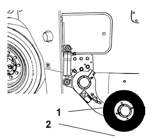
If the edge cutter and its components are dismounted, make sure that it is made with the machine in a safe position and that it is on the ground.
Safety - Option items
Working lights - Xenon
CAUTION! High voltage!
The working lights are Xenon type and have a high voltage auxiliary source of power.
Any maintenance on the lighting system shall be performed by authorized technicians and the main power source shall be off.
CAUTION! Environmentally hazardous waste!
The xenon lamps of the working lights contain mercury (Hg).
A defective lamp is considered a hazardous waste and shall be disposed of properly, according to the applicable local directives.
Contact an DYNAPAC dealer!
Safety – Option items
Technical Specifications
Vibrations – Operator station (ISO 2631)
The vibration levels are measured according to the operational cycle described in the EU directive 2000/14/EC on machines equipped for the EU market with the operator’s seat in the transport position.
The measured vibrations on the whole body are below the 0.5 m/s² action value, as specified in the directive 2002/44/CE (the limit is 1.15 m/s²).
The measured vibrations on the hand/arm are also below the 2.5 m/s² action value, as specified in the same abovementioned directive (the limit is 5 m/s²).
Noise level
The sound levels are measured according to the operational cycle described in the EU directive 2000/14/EC on machines equipped for the EU market with the operator’s seat in the transport position.
During normal operations, the values abovementioned may differ, depending on the work specific conditions.
Electrical system
The machines were tested for electromagnetic compatibility (EMC) in accordance with EN 13309:2000: "Construction machinery".
Technical specifications
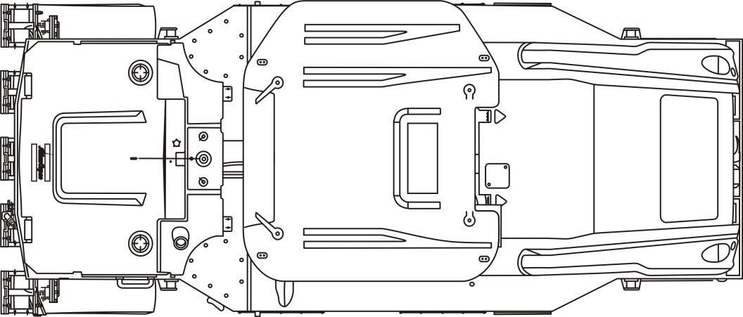
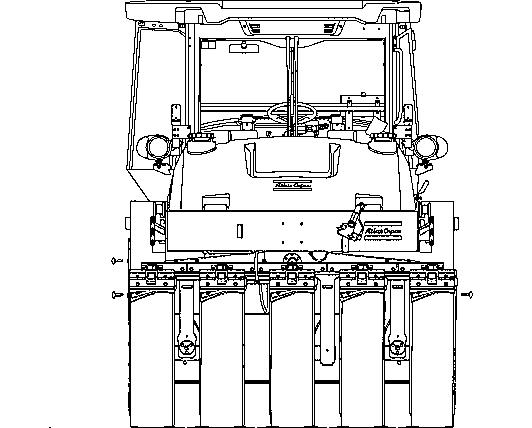
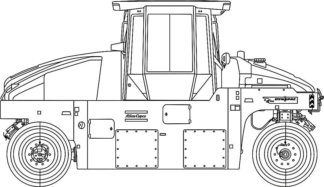
Safety decals - description and location
Safety decals - Description and location (cont.)
Always make sure that all the safety decals are completely legible and remove the dirt or request for new ones if they are illegible. Use the part number indicated on each decal.
NOTICE: Crush zone, wheel. Keep a safe distance from the crush zone.
NOTICE:
Rotating engine components, be careful! Keep your hands off the danger zone.
NOTICE: Hot surface! Keep your hands off the surface.
NOTICE: Read carefully the towing chapter before releasing the brakes. Crushing injury danger.
NOTICE:
The operator must read the Safety and Engine Manuals, as well as the Operation and Maintenance instructions.
NOTICE: High pressure fluid. Make sure to release the pressure from the accumulators before opening the hydraulic system.
NOTICE: Gas shall not be use to start the machine.
NOTICE: Edge cutter (option).
NOTICE: Toxic gas danger. Refer to the Instruction Manual.
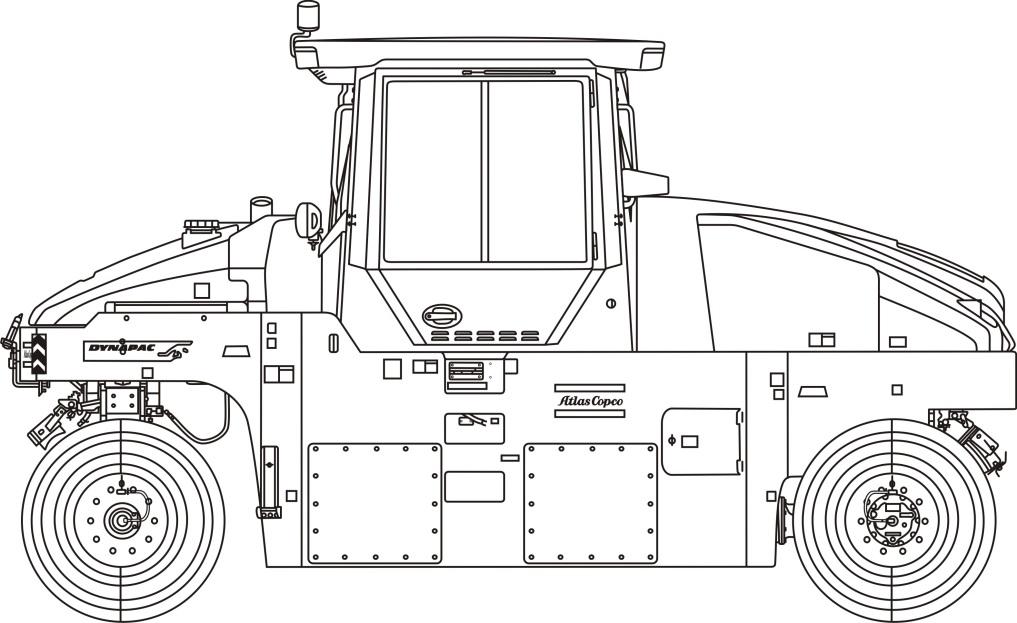
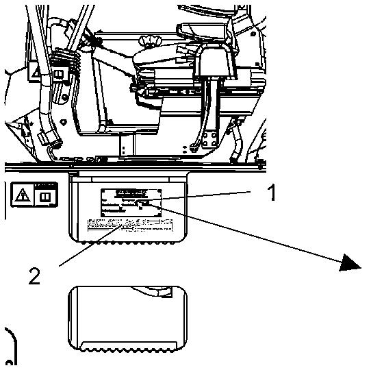
Identification plates
Identification plates Machine plate.
The machine plate (1) is on the top step, on the left side of the operator's platform.
It specifies the manufacturer's name, the type of the machine, the serial number, the service weight, the engine power and the manufacturing year (machines delivered outside EU do not present CE marking and in some cases they also do not present the manufacturing year).
NOTE: State the machine plate's serial number when ordering spare parts.
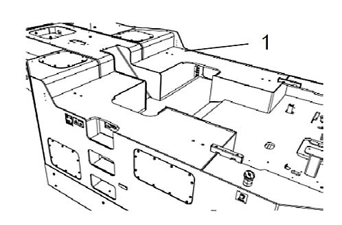
PIN (Product Identification Number) at the frame
The PIN - product identification number (1) is punched on the right side of the right frame. It is the same number of the machine plate (serial number).
Identification plates
Explanation of the 17PIN (Product Identification Number)
A – Manufacturer's code (100 = Dynapac)
B – Family/model code (00502 = CP2700)
C – Check code
D – Year of manufacturing (E=2014, F=2015...)
E – Production's unit code (B = Sorocaba, Brazil)
F – Serial number (from 000001 to 999999)
Engine plate
The engine plate (1) is on the cylinder head cover (1), and it can be accessible when the hood is open.
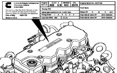
The plate is also on the top step of the operator's platform. It contains information like the serial number and the engine specifications.
NOTE: State the engine plate's serial number when ordering spare parts.
Identification plates
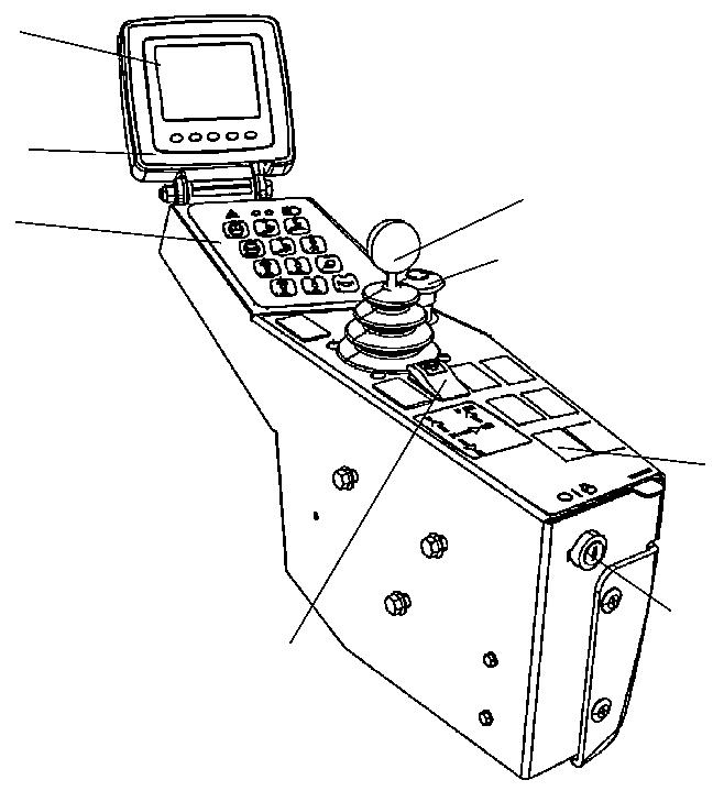
Instruments/controls
Control panel, side panel and command keyboard.
7.
16.
17.
18.
19.
2019-11-06
Pedals
The roller has two pedals:
1. Throttle pedal
2. Brake pedal
Steering column multiple switch (option)
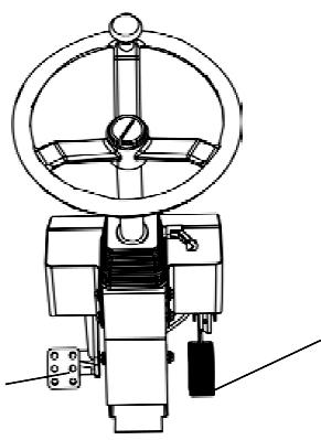

Switch functions:
1. Forward/reverse lever
2. Central warning lights
3. Direction lights
No. DESIGNATION
1 Ignition key
Instrument/controls - Description and function
Instrument/controls - Description and function
SYMBOL FUNCTION
The electric circuit is off.
All instruments and electric controls are on.
The starter is activated.
2 Forward/reverse lever - To start the machine, the lever shall be in the "neutral" position. Move the lever forward and step on the throttle to drive forwards; move the lever back and step on the throttle to drive backwards.
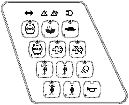
3 Command keyboard -
4 Direction lights
5 Central warning lights
6 High beam lights
7 "+" increase in the tire pressure
It shows that the direction lights are activated (activation via switch at the steering column).
Appoints general fault. See the control panel (22) for the description of the fault.
It shows that the high beam lights are on (via switch at the steering column).
When activated, it increases the tires pressure.
8 "-" decrease in the tire pressure
When activated, it decreases the tires pressure.
9 High/low speed
10 Manual sprinkler
11 Automatic sprinkler
12 "+" increase of the sprinkler interval (timer)
The roller starts always in the high speed mode. The low speed mode is obtained when activated.
Gives continuous sprinkling of water on the wheels.
When activated, sprinkling is automatically turned on/off when the forward/reverse lever is in the "neutral" position.
The sprinkling frequency increases each time the water volume on the wheels is also increased.
4812314581EN
2019-11-06
Instrument/controls - Description and function
Instrument/controls - Description and function (cont.)
No. DESIGNATION
13 "-" decrease of the sprinkler interval (timer)
14 Working lights
SYMBOL FUNCTION
The sprinkling frequency decreases each time the water volume on the wheels is also decreased.
Press to turn on/off all the working lights.
15 Horn switch
16 Emergency stop button
Press to sound the horn.
17 Eco-mode
18 Button to enable the regeneration (Tier IV Engine)
19 Button to disable the regeneration (Tier IV Engine)
20 Hazard warning lights
Press it to turn off the machine and the engine. All the power supply is also turned off.
When activated, maintain speed reducing the engine rotation, thus saving fuel (up to 30% economy)
Press to execute the regeneration
Press to disable regeneration.
Press the switch to activate the hazard warning lights.
21 Rotating beacon
Press the switch to activate the rotating beacon.
2019-11-06
No. DESIGNATION
22 Control panel
Instrument/controls - Description and function
Instrument/controls
SYMBOL FUNCTION
- It shows the engine and transmission functions. Refer to the Section: "Before Starting".
23 Function buttons (5) -
24 Brake test pedal Press it to test the brakes.
25 Parking brake
26 Edge cutter
When it is pressed, the parking brake is activated.
To turn it off, slide the red part backwards (towards you) and change the switch position.
NOTE: to start the machine, the parking brake shall be activated.
The edge cutter can be moved up and down when machine is in work postion.
27 Edge sprinkler Press to activate the edge cutter sprinkler
4812314581EN 2019-11-06
Control panel – General description
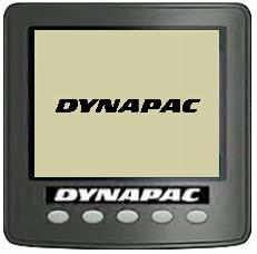
When the ignition key is in the position "I", the start screen is visible on the display. It remains activated for a few seconds then it switches to the status screen.
The status screen provides information about the fuel level, the sprinkler tank water level, the working hours and the voltage level. The water and fuel levels are specified in percentage (%).
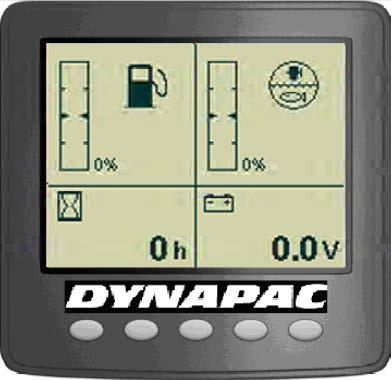
The screen remains visible until the Diesel engine is turned on or if one of the function buttons below the screen is pressed.
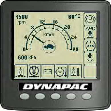
If the engine starts before you choose the screen, it will switch to the main screen.
This screen provides an overview and it remains on during the operation:
- The speed is shown in the middle of the screen.
- The high/low speed mode is shown with a symbol in the middle of the screen.
- The engine rpm, the asphalt temperature (option) and the tires pressure (option) are shown in the upper left corner and in the lower left corner, respectively.
Instrument/controls - Description and function
Control panel – General description (cont.)
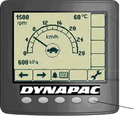
A menu field is shown by pressing one of the selection buttons. It is visible for a short time, then it fades out if any selection is made. A menu field appears again by pressing one of the selection buttons (1).
Scroll/selection buttons to choose the available functions.
Alarm log button to show the alarms of the engine and machine.
Settings/menu selection button, which opens the main menu. Settings can be changed in the main menu.
Exit/return button, returns 1 step at once. Pressing the button for approximately 2 seconds displays the main menu again.
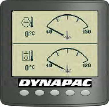
The temperature screen shows the engine oil (top of the screen) and hydraulic oil temperature (bottom of the screen). The values are shown in Celsius or Fahrenheit, according to the choice of unit system.
Control panel - Alarms
It is also possible to refer to a menu with the asphalt temperature when the asphalt temperature gauge (option) is installed. Set the upper and lower temperature limits with the function keys.
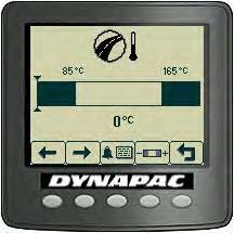
If the asphalt effective temperature is outside the limits, the value shown in the top of the main screen starts to flash. The temperature value is continuously on when it is in the right limit.
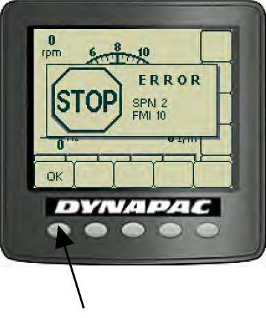
When an engine motor alarm is activated, it is shown in the screen. The alarm is sent from the engine's ECM, which tracks its functions.
The message displays SPN and FMI codes and can be read via the engine supplier error code list. To erase the message, press "OK".
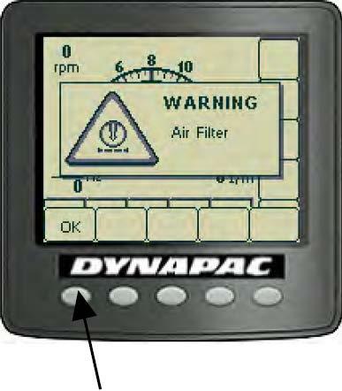
When a machine's alarm is activated, it is shown in the screen with a warning text describing it.
To erase the message, press "OK".

