66 minute read
Instruction Manual

from Dynapac Pneumatic Tire Roller CP2100 CP2100W Operating & Maintenance Manual 4812314580 PDF DOWNLOAD
4812314580EN
Operation and Maintenance
Pneumatic Tire Roller
CP2100 / CP2100W
Diesel Engine
Cummins QSB 3.3 – Tier III
Cummins QSF 3.8 - Tier IV
Serial number
Table Of Contents
Introduction
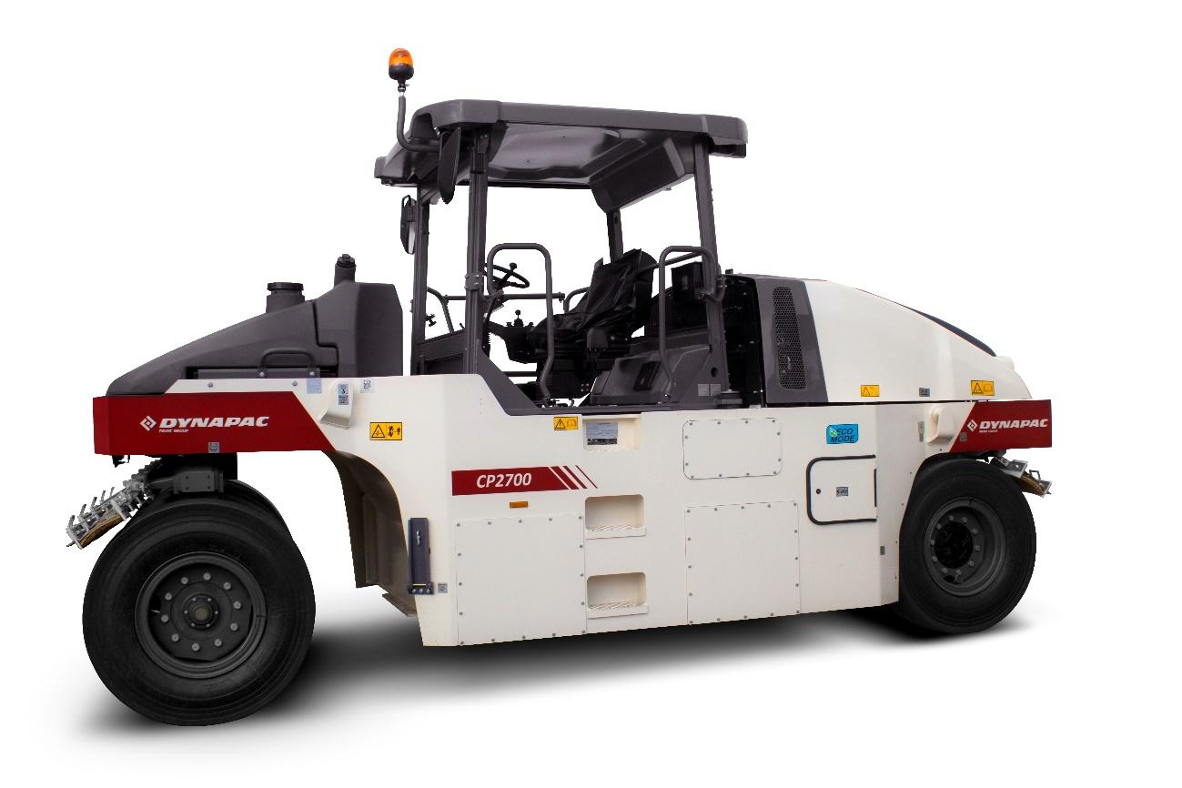
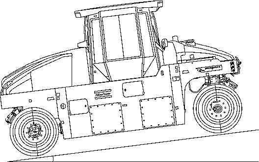
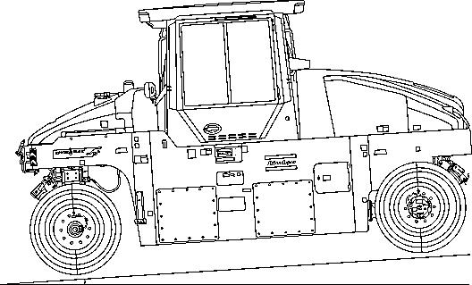
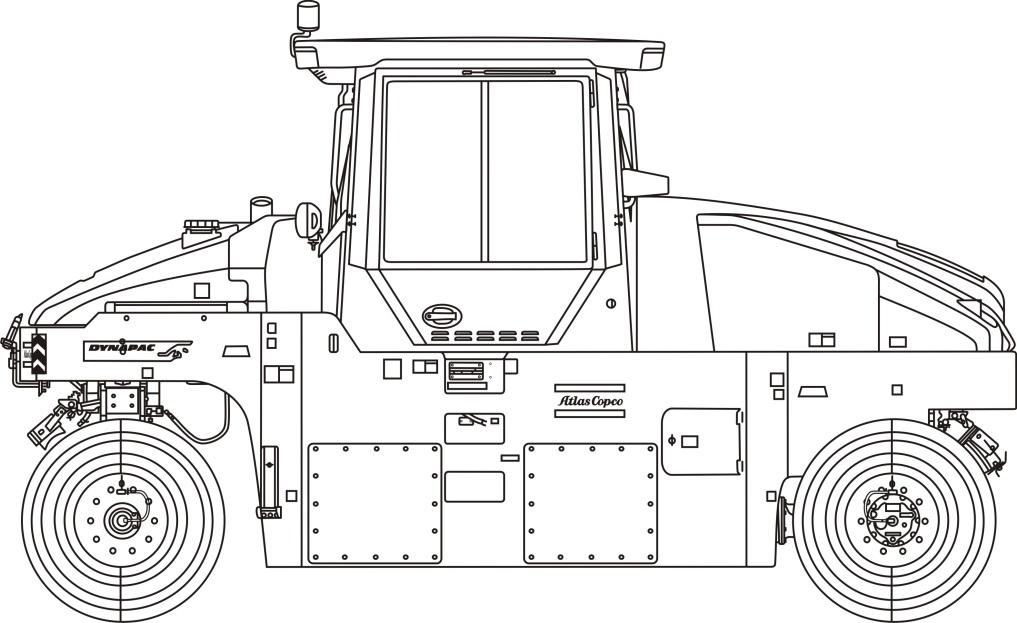
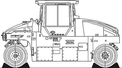
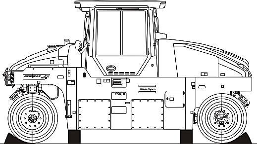
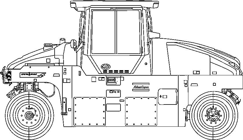
Dynapac CP2100 / CP2100W
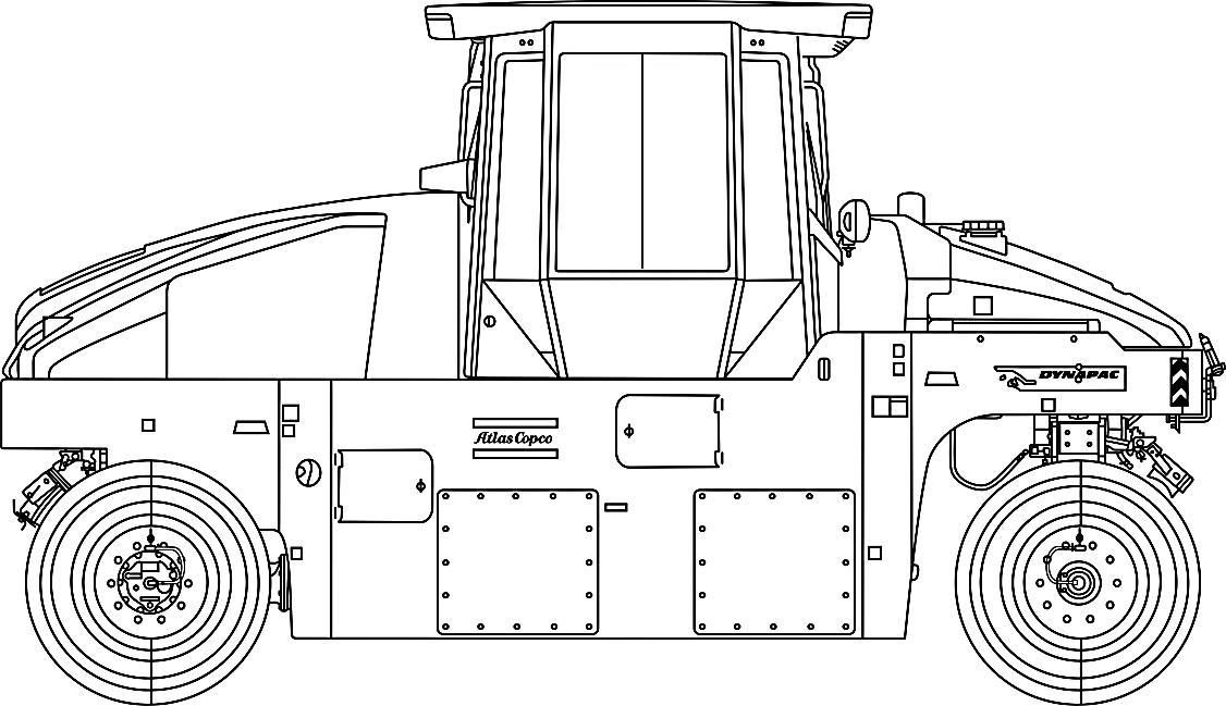
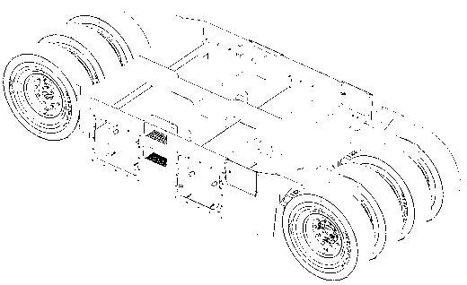
Dynapac CP2100 is a 21 tones rubber wheel roller, with 5,905 ft (1,800 m) width. CP2100 is also available on the wide base version (CP2100W), with larger tires and 7,480 ft (2,280 m) width.
It has three direction front wheels and four back wheels. The hydrostatic drivers, the flexible ballast solution and a wide range of option equipment indicate that the machine has different settings available. CP2100 is mainly used together with other asphalt rollers to seal surfaces. Thanks to its weight, it also serves as a roller for other types of ground.
Warning symbols
WARNING! Damage to the machine or its parts.
CAUTION! Risk of death or injures.
Safety information
The Safety Manual delivered with the machine shall be read by the operator. Always follows the safety instructions and keep the Manual inside the machine.
It is recommended to at least train the operators on daily handling and maintenance of the machine, according to the Instruction Manual. Passengers are not allowed on the machine, and the operator must be on the seat whenever he operates the equipment.
Read throughout the manual before starting the machine and before performing any maintenance.
Request immediately new manuals if the old ones are lost damaged or become illegible.
Make sure there is a good vent (air exhaust) when the engine is turned on in closed facilities.
General Information
This manual contains instructions to operate and perform the maintenance of the machine.
The machine's maintenance shall be made correctly in order to obtain the maximum performance and the equipment shall also be kept clean, so leakage, loosen bolts and connections can be found as soon as possible.
Perform a daily inspection in the machine before starting, so you can find possible leakage or other failures.
Verify the machine's floor. Leakages are easier detected on the floor than on the equipment itself.
THINK ABOUT THE ENVIRONMENT! Do not dispose oil, fuel or other hazard substances to the environment. Always dispose correctly used filters, draining oil and fuel residues.
This manual contains instructions for periodic maintenance, which is usually performed by the operator.
Other engine instructions can be found at the manufacturer's manual.
CE Marking and Statement of Compliance
(APPLIED TO MACHINES SOLD WITHIN THE EUROPEAN COMMUNITY)
This machine has a CE Marking. It shows that at its delivery, it meets all the applicable health and safety basic directives, according to 2006/42/EC Machinery Directive, besides attending other directives applicable on machinery.
Following the machine there is a "Statement of Compliance" specifying the directive and supplement applicable, as well as the harmonized norms and other regulations relevant to the case.
Safety - General instructions
Safety - General instructions
(you must also read the Safety Manual)
1. Read and understand this Manual before starting and operating the machine. The operator must be familiar with the equipment contents before operating it.
2. Observe and follow all the Maintenance Section instructions.
3. Only experienced/trained operators are allowed to operate the machine. NEVER allow the presence of passengers and ALWAYS remain seated while operating the equipment.
4. Do not operate the equipment if adjustment or repairs are necessary.
5. Use ladders and rails to enter and leave the cab. NEVER enter or leave the machine while it is moving.
6. The ROPS (Roll Over Protective Structure) should always be used when the machine is operated on unsafe ground. Always use the seat belt when the ROPS is on.
7. Use the first gear on sharp turns.
8. Avoid driving close to cliffs or sharp side slopes. Operate the machine on first gear and always check the brakes.
9. When driving close to edges or holes, make sure at least 2/3 of the wheels are on the previously compacted materials.
10. Make sure there are no obstacles over your head during the travel. Always look up and down during the travel. Make sure there are no obstacles in the direction of travel - on the ground, in front or behind the roller.
11. Drive particularly carefully on uneven ground.
12. Follow all the safety rules and use the protection equipment proper to the work to be performed.
13. Keep the roller clean. Clean immediately dirt, oil and grease accumulated on the operator platform. Keep all the signs, lanterns, headlights and decals clean, visible and legible.
14. Observe the following safety measures before refueling:
- Turn off the engine;
- Do not smoke;
- Do not allow sparks or flame next to the equipment;
- To avoid sparks, ground the filling nozzle.
15. Before performing any maintenance operation, chock the roller wheels and apply the emergency/parking brakes.
16. Hearing protection is recommended if the machine's noise level exceeds 85 dB (A). The noise level can vary depending on the work the machine performs.
17. Do not make any changes on the machine, under the risk of affecting the personal safety as well the equipment's. Any change on the machine demands a previous written approval by DYNAPAC.
18. Avoid using the machine before the hydraulic oil reaches the normal operating temperature. The braking distance may be longer than normal if the oil is cold. Refer to the operation instructions on "Stop", in the "Operation" section.
19. For your own protection, always wear:
- Helmet;
- Working boots with steel toecaps;
- Ear protectors;
- Reflecting clothing;
- Working gloves.
20. If there is a cab in the machine, operate it always with the doors closed and with the seat belt.
Safety - When operating
Avoid people entering at the danger area, that is, at a distance of at least 23 ft (7 m) in all the directions from the machine operating. The operator can allow one person to be at the danger area, but in this case, care must be taken and the machine can only be operated when this person is in a visible place or with clear indication of where he/she is.
Operating on slopes
The machine must never be operated from the outside of the cab. The operator shall be seated when operating.
Slopes
This angle was measured on a flat, hard surface and with the machine in a stationary position.
The steering angle is zero, the tires pressure is normal and all the tanks are full.
Always remember that loosen ground, the steering of the machine, different tire pressures, the operation speed and the gravity center raising may cause the machine to turn, even on slopes smaller than the ones stated here.
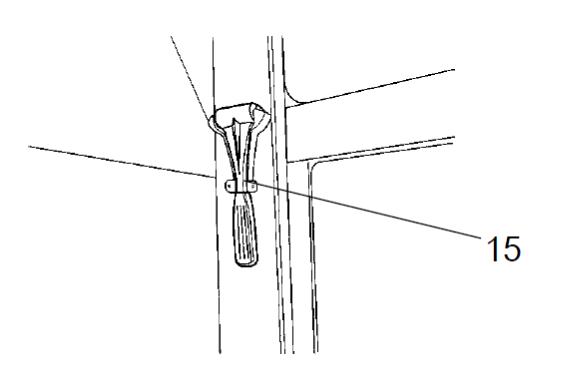
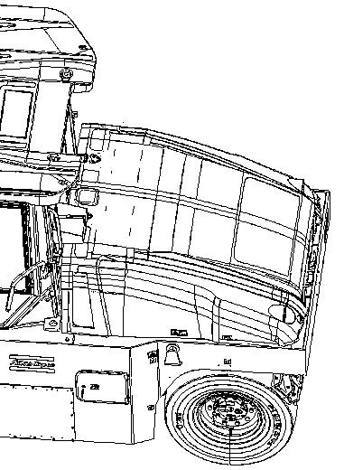
If you need to leave the cab in emergency situations, take off the hammer at the rear pillar on the right and break the opening windows that are also on the right.
It is recommended that ROPS (Roll Over Protective Structure) is always used when driving on slopes or unsafe ground.
Whenever possible, avoid driving across slopes. On slopes, drive straight up and down.
The speed must always be slow when operating on slopes.
Always operate the machine with the doors closed and with the seat belt.
>5% (2.8°)
(9.3 mph
15 km/h).
Transport on steep ground
During the transport on steep ground (slope >5%), be careful to not exceed the roller's maximum speed.
Take your foot off the throttle pedal and use the engine brake system. Also use the main brake if the speed keeps increasing. Selecting the low speed will increase the engine brake system efficacy and also the life of the braking system.
Operation and transport on steep ground
Always drive the machine in slow speed when operating or during transport on steep ground.
(>15%).
To drive or stop the machine, the rear wheels shall always be towards the slope, that is, the roller shall go up normally and shall go down in reverse.
>15% (8.5°)
4.7 mph or 7.5 km/h)
Make sure there are no obstacles both in front or behind your work area.
Driving near edges
When driving close to edges or holes, make sure that at least ¼ of the tires is on the compacted ground.
At least 1/4
Safety – Option items
Air conditioning
The system contains pressurized refrigerant. It is forbidden to release refrigerant to the atmosphere.
The maintenance of the air conditioning system shall be carried out only by trained people and with the proper tools and equipment.
The air conditioning system is pressurized. The incorrect handling can result in serious personal injury. Do not loose or disconnect hoses and connections with the system loaded.
The system must be refilled with approved coolant when necessary. Refer to the safety decal next to the replacement and filling place.
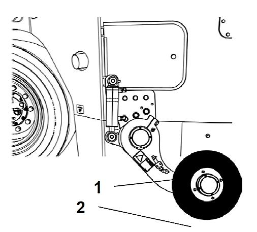
Edge cutter
The operator must make sure that nobody is in the work place when the machine is operating.
The edge cutter has rotating components which may cause crushing.
Immediately after use, the tool shall always be put back on the transport position (1) that is, on the raised position.
If the edge cutter and its components are dismounted, make sure that it is made with the machine in a safe position and that it is on the ground.
Working lights - Xenon
CAUTION! High voltage!
The working lights are Xenon type and have a high voltage auxiliary source of power.
Any maintenance on the lighting system shall be performed by authorized technicians and the main power source shall be off.
CAUTION! Environmentally hazardous waste!
The xenon lamps of the working lights contain mercury (Hg).
A defective lamp is considered a hazardous waste and shall be disposed of properly, according to the applicable local directives.
Contact an DYNAPAC dealer!
Technical Specifications
Vibrations – Operator station (ISO 2631)
The vibration levels are measured according to the operational cycle described in the EU directive 2000/14/EC on machines equipped for the EU market with the operator’s seat in the transport position
The measured vibrations on the whole body are below the 0.5 m/s² action value, as specified in the directive 2002/44/CE (the limit is 1.15 m/s²).
The measured vibrations on the hand/arm are also below the 2.5 m/s² action value, as specified in the same abovementioned directive (the limit is 5 m/s²).
Noise level
The sound levels are measured according to the operational cycle described in the EU directive 2000/14/EC on machines equipped for the EU market with the operator’s seat in the transport position.
During normal operations, the values abovementioned may differ, depending on the work specific conditions.
Electrical system
The machines were tested for electromagnetic compatibility (EMC) in accordance with EN 13309:2000: "Construction machinery".
Technical specifications
1
Safety decals - description and location
Safety decals - Description and location (cont.)
Always make sure that all the safety decals are completely legible and remove the dirt or request for new ones if they are illegible. Use the part number indicated on each decal.
WARNING: Crush zone, wheel. Keep a safe distance from the crush zone.
WARNING:
Rotating engine components, be careful! Keep your hands off the danger zone.
WARNING: Hot surface! Keep your hands off the surface.
WARNING:
Read carefully the towing chapter before releasing the brakes. Crushing injury danger.
WARNING: The operator must read the Safety and Engine Manuals, as well as the Operation and Maintenance instructions.
WARNING: High pressure fluid. Make sure to release the pressure from the accumulators before opening the hydraulic system.
WARNING: Gas shall not be use to start the machine.
WARNING: Edge cutter (option).
WARNING:
Toxic gas danger. Refer to the Instruction Manual.
Identification plates
Identification plates Machine plate.
The machine plate (1) is on the top step, on the left side of the operator's platform.
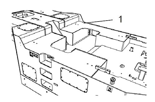
It specifies the manufacturer's name, the type of the machine, the serial number, the service weight, the engine power and the manufacturing year (machines delivered outside EU do not present CE marking and in some cases they also do not present the manufacturing year).
NOTE: State the machine plate's serial number when ordering spare parts.
PIN (Product Identification Number) at the frame
The PIN - product identification number (1) is punched on the right side of the right frame. It is the same number of the machine plate (serial number).
Identification plates
Explanation of the 17PIN (Product Identification Number)
A – Manufacturer's code (100 = Dynapac)
B – Family/model code (00501 = CP2100)
C – Check code
D – Year of manufacturing (E=2014, F=2015...)
E – Production's unit code (B = Sorocaba, Brazil)
F – Serial number (from 000001 to 999999)
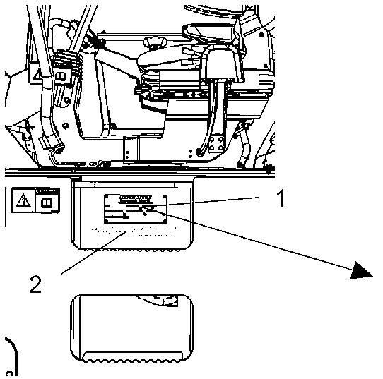
Engine plate
The engine plate (1) is on the cylinder head cover (1), and it can be accessible when the hood is open.
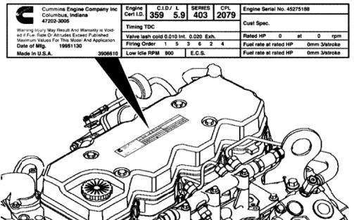
The plate is also on the top step of the operator's platform.
It contains information like the serial number and the engine specifications.
NOTE: State the engine plate's serial number when ordering spare parts.
Instruments/controls
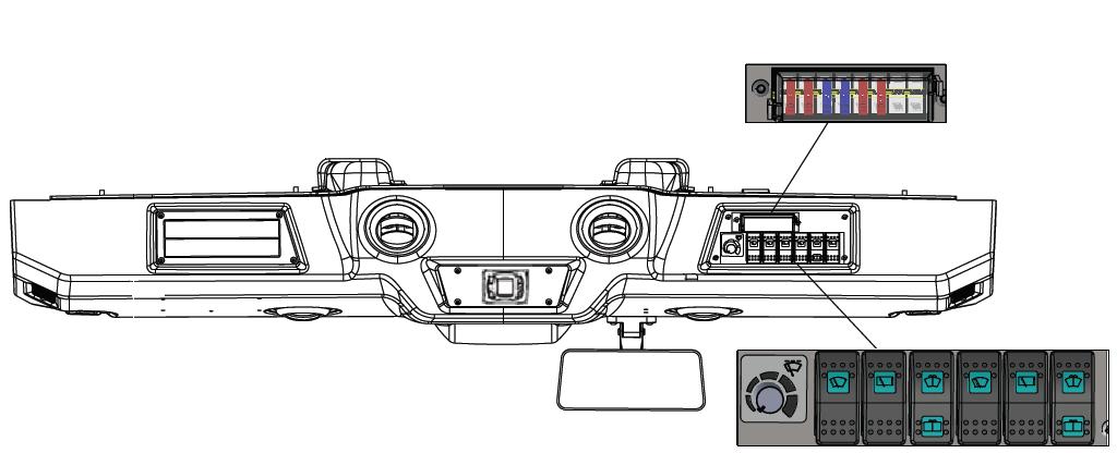
Control panel, side panel and command keyboard.
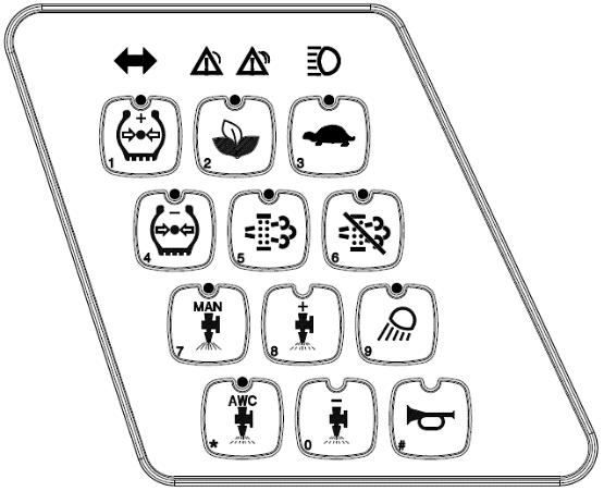
1. Ignition key
2. Forward/reverse lever
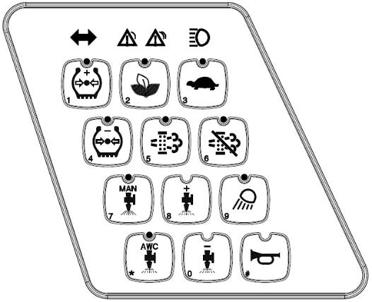
3. Command keyboard
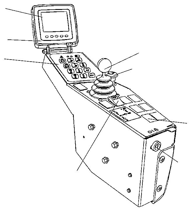
4. Direction lights (OPTION)
5. Warning lights
6. High beam lights (OPTION)
7. "+" increase in the tire pressure (OPTION)
8. "-" decrease in the tire pressure (OPTION)
9. High/low speed
10. "MAN" manual sprinkler (OPTION)
11. "AWC" automatic sprinkler (OPTION)
12. "+" increase of the sprinkler interval (timer) - OPTION
13. "-" decrease of the sprinkler interval (timer) - OPTION
14. Working lights (OPTION)
15. Horn
16. Emergency stop button
17. Eco-mode
18. Enable regeneration (Tier iV engine)
19. Disable regeneration (Tier iV engine)
20. Hazard warning lights (OPTION)
21. Rotating beacon (OPTION)
22. Control panel
23. Function buttons (5)
24. Brake test pedal
25. Parking brake
26. Edge cutter (OPTION)
27. Edge cutter sprinkler(OPTION)
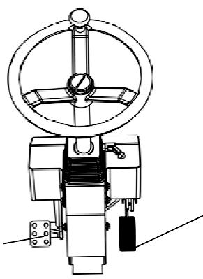
Pedals
The roller has two pedals:
1. Throttle pedal
2. Brake pedal
Steering column multiple switch (option)
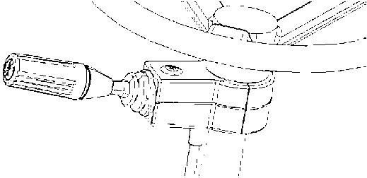
Switch functions:
1. Forward/reverse lever
2. Central warning lights
3. Direction lights
No. DESIGNATION
1 Ignition key
Instrument/controls - Description and function
Instrument/controls - Description and function
SYMBOL FUNCTION
The electric circuit is off.
All instruments and electric controls are on.
The starter is activated.
2 Forward/reverse lever - To start the machine, the lever shall be in the "neutral" position. Move the lever forward and step on the throttle to drive forwards; move the lever back and step on the throttle to drive backwards.
3 Command keyboard -
4 Direction lights
5 Central warning lights
6 High beam lights
7 "+" increase in the tire pressure
It shows that the direction lights are activated (activation via switch at the steering column).
Appoints general fault. See the control panel (22) for the description of the fault.
It shows that the high beam lights are on (via switch at the steering column).
When activated, it increases the tires pressure.
8 "-" decrease in the tire pressure
When activated, it decreases the tires pressure.
9 High/low speed
10 Manual sprinkler
11 Automatic sprinkler
12 "+" increase of the sprinkler interval (timer)
The roller starts always in the high speed mode. The low speed mode is obtained when activated.
Gives continuous sprinkling of water on the wheels.
When activated, sprinkling is automatically turned on/off when the forward/reverse lever is in the "neutral" position.
The sprinkling frequency increases each time the water volume on the wheels is also increased.
4812314580EN
2020-01-06
No. DESIGNATION
13 "-" decrease of the sprinkler interval (timer)
14 Working lights
15 Horn switch
16 Emergency stop button
17 Eco-mode
18 Button to enable the regeneration (Tier IV Engine)
19 Button to disable the regeneration (Tier IV Engine)
20 Hazard warning lights
21 Rotating beacon
Instrument/controls - Description and function (cont.)
SYMBOL FUNCTION
The sprinkling frequency decreases each time the water volume on the wheels is also decreased.
Press to turn on/off all the working lights.
Press to sound the horn.
Press it to turn off the machine and the engine. All the power supply is also turned off.
When activated, maintain speed reducing the engine rotation, thus saving fuel (up to 30% economy)
Press to execute the regeneration
Press to disable regeneration.
Press the switch to activate the hazard warning lights.
Press the switch to activate the rotating beacon.
Instrument/controls - Description and function 2020-01-06
22 Control panel
Instrument/controls
- It shows the engine and transmission functions. Refer to the Section: "Before Starting".
23 Function buttons (5)24 Brake test pedal
Press it to test the brakes.
25 Parking brake
26 Edge cutter
When it is pressed, the parking brake is activated.
To turn it off, slide the red part backwards (towards you) and change the switch position.
NOTE: to start the machine, the parking brake shall be activated.
The edge cutter can be moved up and down when machine is in work postion.
Press to activate the edge cutter sprinkler.
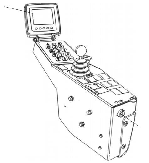
Control panel – General description
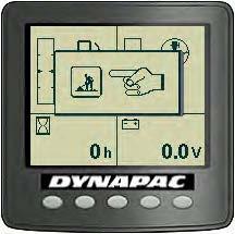
When the ignition key is in the position "I", the start screen is visible on the display. It remains activated for a few seconds then it switches to the status screen.
The status screen provides information about the fuel level, the sprinkler tank water level, the working hours and the voltage level. The water and fuel levels are specified in percentage (%).
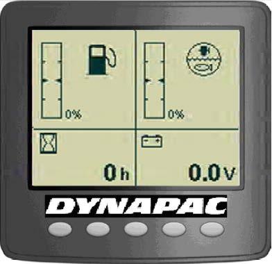
The screen remains visible until the Diesel engine is turned on or if one of the function buttons below the screen is pressed.
If the engine starts before you choose the screen, it will switch to the main screen.
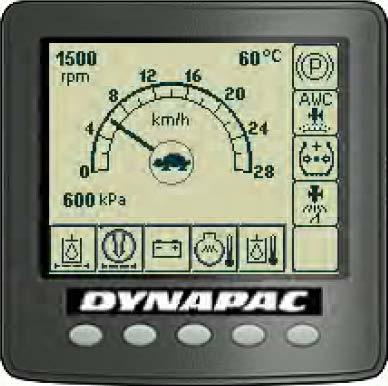
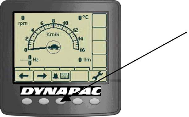
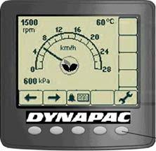
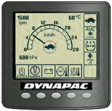
This screen provides an overview and it remains on during the operation:
- The speed is shown in the middle of the screen.
- The high/low speed mode is shown with a symbol in the middle of the screen.
- The engine rpm, the asphalt temperature (option) and the tires pressure (option) are shown in the upper left corner and in the lower left corner, respectively.
Control panel – General description (cont.)
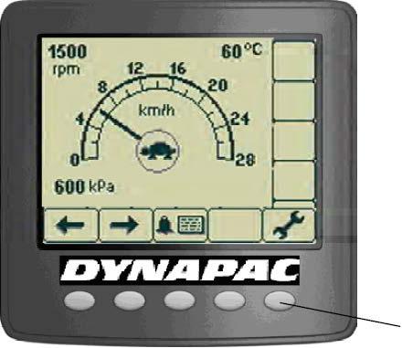
A menu field is shown by pressing one of the selection buttons. It is visible for a short time, then it fades out if any selection is made. A menu field appears again by pressing one of the selection buttons (1).
Scroll/selection buttons to choose the available functions. Alarm log button to show the alarms of the engine and machine. Settings/menu selection button, which opens the main menu. Settings can be changed in the main menu.
Exit/return button, returns 1 step at once. Pressing the button for approximately 2 seconds displays the main menu again.
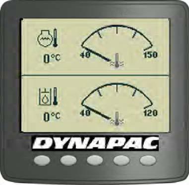
The temperature screen shows the engine oil (top of the screen) and hydraulic oil temperature (bottom of the screen). The values are shown in Celsius or Fahrenheit, according to the choice of unit system.
Control panel - Alarms
It is also possible to refer to a menu with the asphalt temperature when the asphalt temperature gauge (option) is installed. Set the upper and lower temperature limits with the function keys.
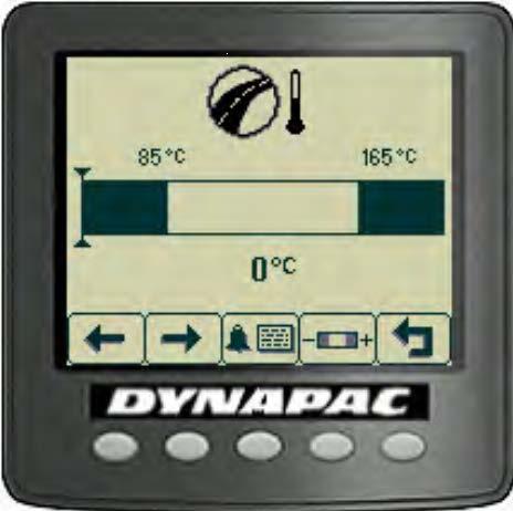
If the asphalt effective temperature is outside the limits, the value shown in the top of the main screen starts to flash. The temperature value is continuously on when it is in the right limit.
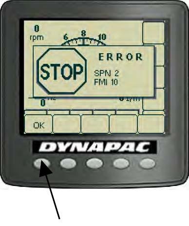
When an engine motor alarm is activated, it is shown in the screen. The alarm is sent from the engine's ECM, which tracks its functions.
The message displays SPN and FMI codes and can be read via the engine supplier error code list. To erase the message, press "OK".
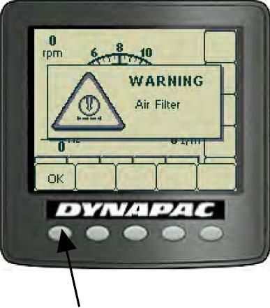
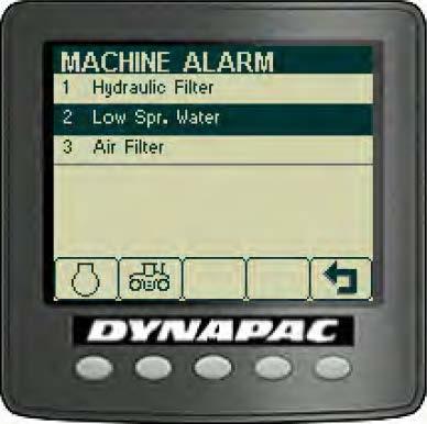
When a machine's alarm is activated, it is shown in the screen with a warning text describing it.
To erase the message, press "OK".
Control panel – Alarms (cont.)
Symbol Description
Warning symbol, hydraulic oil filter.
Warning symbol, air filter.
Warning symbol, battery charging.
Function
If the symbol appears with the engine in maximum rpm, it shall be necessary to replace the hydraulic oil.
If the symbol appears with the engine in maximum rpm, it shall be necessary to clean or replace the air filter.
If the symbol appears with the engine running, the alternator is not charging. Stop the engine and find the fault.
Warning symbol, engine temperature.
If this symbol appears, the engine is too hot. Stop immediately the engine and find the fault. Refer also to the engine manual.
Warning symbol, hydraulic oil temperature.
Warning symbol, low fuel level.
Warning symbol, low sprinkler water level.
This symbol appears when the hydraulic oil is too hot. Do not drive the roller, put the engine on idle, wait until the oil cools down and find the fault.
This symbol appears when the fuel level is 10%.
This symbol appears when the sprinkler water level is 10% in the main tank.
Warning symbol, low braking capacity.
This symbol appears when the oil level and/or pressure for the brakes are low. If this alarm appears and remains with the machine working, stop it immediately and contact DYNAPAC
Instrument/controls - Description and function
Fail list
The machine stops and cannot be used before the fault is corrected.
Control panel – Alarms (cont.)
Alarms received are stored/logged and can be seen by selecting Display Alarms. .
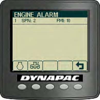
“ENGINE ALARM”
Stored/logged engine alarms.
“MACHINE ALARM”
Stored/logged machine alarms. They come from other systems on the machine.
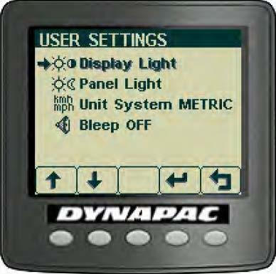
“USER SETTINGS”
Users can change lighting settings, choose between Metric or Imperial system and set warning sounds on/off.
Adjustment of light and contrast settings on the display, including brightness of the panel light.


Operator help when starting
Emergency procedures
When trying to turn on the machine without having set up to three necessary conditions to do so, the missing ones are shown in the display. The missing conditions must be set before turning on the machine.
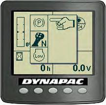
Conditions that must be set:
- The parking brake shall be activated.
- The forward/reverse lever shall be in the neutral position.
- The Diesel engine rpm shall be in the low speed (low = slow speed) (not all the models, refer to the manual to know if your model fits in this condition).
Operator help when activating
When trying to activate the edge cutter (option) with the machine in high speed, the display will show the slow speed mode for a few seconds.
To activate the previous function, make sure the low speed mode is activated.
Eco-mode
This equipment has a new fuel economy system.
When activated the Eco-mode maintain work speed decreasing the engine rotation (≈1700 rpm), so the fuel economy can reach 30% depending on work (slopes, ballast, etc).
Don´t use Eco-mode on slopes higher that 15%.
Emergency procedures
Regeneration system (Emission Control)
This equipment has a system of emission control and need special care during the operation. This system has a particulate filter (DPF) which accumulates pollutants throughout the operation and must go through a regeneration process that happens automatically, to eliminate the accumulated material. When the machine is stationary with the engine running, if necessary, the regeneration system will start.
! During regeneration, the engine increases its operation speed.
! Whenever regeneration is initiated, it is advisable to wait with the equipment on and stopped to completion.
The equipment controls the level of contamination of the DPF in 5 stages: Empty, Low, Medium, High and Service.

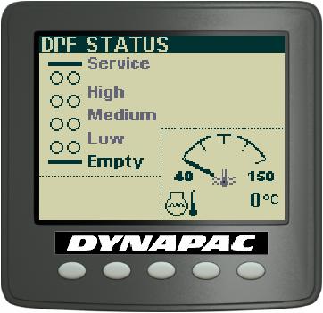
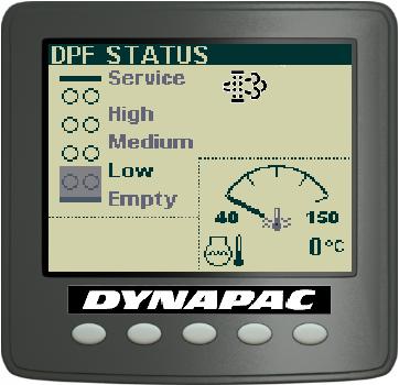
When the accumulation in the DPF reaches the low level (Low) contamination, the alert will be shown regeneration, indicating that the machine will trigger automatic regeneration if the machine is stopped.
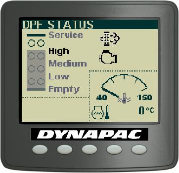
When the accumulation in DPF reach the average level (Medium) of contamination, the alert ‘regeneration’ flashes and yellow alert ‘engine’ is activated. In this condition, it is recommended to stop the machine at the first opportunity to perform regeneration.
Emergency procedures
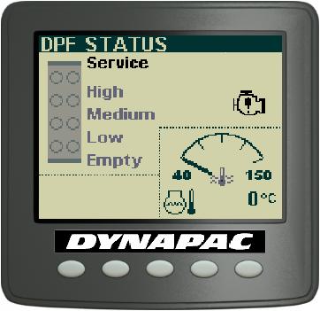
When the high level (High) contamination is achieved, the equipment will be turned off and the engine red alert will be triggered. Under these conditions, we recommend stop the machine immediately and let it perform the regeneration completely.
Attention! If the accumulation of the DPF reaches maximum level (Service) equipment is locked and the system is unable to regenerate itself. Under these conditions, cleaning the filter can only be performed manually by a skilled technician Cummins.
Attention! Inhibition should only be used in exceptional cases, when the machine has to be stopped and there is still a small part of work to be completed.
Emergency procedures
No. DESIGNATION
Instruments and controls - Cab
SYMBOL FUNCTION
1 Automatic Climate Control - Air conditioning automatic control (see A/C operation for detail)
2 Front wiper, intermittent - Intermittent function for front wiper.
3 Front wiper switch
4 Rear wiper switch
5 Front and rear windshield washers switch
6 Asymmetric front wiper switch
7 Asymmetric rear wiper switch
Press to operate the front windshield wiper.
Press to operate the rear windshield wiper.
Press the top to activate the front washers. Press the bottom to activate the rear washers.
Press to operate the front side windshield wiper.
Press to operate the rear side windshield wiper.
8 Asymmetric side windshield washers switch
Press the top to activate the front side washers. Press the bottom to activate the rear side washers.
9 Fuse box Contains fuses from the electric system in the cab.
10 Hammer for emergency exit
If it is necessary to leave the cab during an emergency, release the hammer and break the right side windows.
11 Defroster nozzle - Turn the defroster nozzle to direct the air flow.
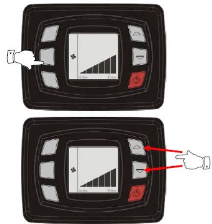
A/C – System operation
Power/Enter
By feeding the panel with 24VDC, the screen will be on, indicating that the product is in standby mode. Press to turn on the A/C, it will show the software version and then the temperature. To return to standby mode you must press the button for 3s.
Set point Up/Down
Set point is the desired temperature inside the vehicle. To set it up press or . The set point temperature will flash on the display; press until reaches desired temperature.
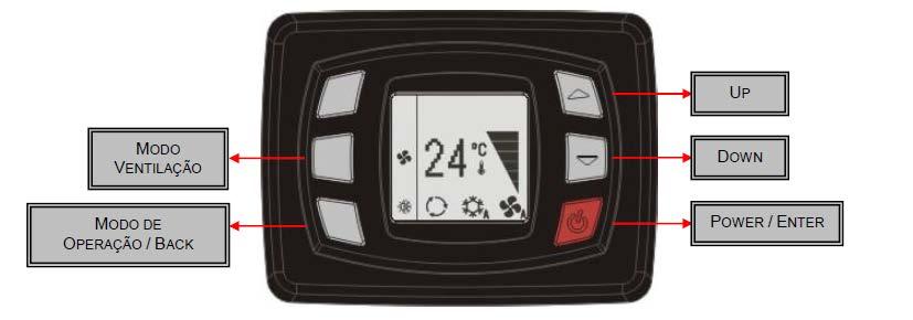

Display
The display shows set point value, bar graph evaporator speed, active function and other information. It also serves to allow the operator to view the coil and return temperature, as well as the parameters. It also serves to alert when there is some system flaws.
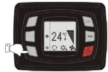
Operation Mode
To change the operation mode, press the button (operation mode), select the desired mode:
The controller has 4 operation modes that are:
- Only ventilation
- Only cooling
- Only heating
- Automatic mode
Press the button to confirm or wait a few seconds to cancel.
Ventilation
The controller has two ventilation modes: manual and automatic ventilation.
Manual ventilation
The manual ventilation has three speeds. When some function (cooling, heating or automatic mode) is active, the ventilation function is always on. To change the fan speed, press the key (Ventilation mode) and after set the desired speed with the keys or After press the key to confirm or wait a few seconds and the speed will be saved
Operation - Before starting
Daily maintenance
Before starting your work shift and operating the equipment, make sure the daily maintenance was carried out. For further information, refer to the maintenance section in this manual.
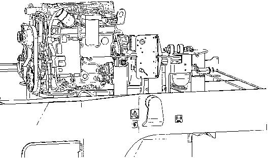
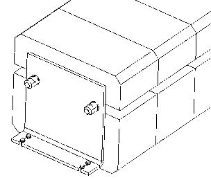
Master switch
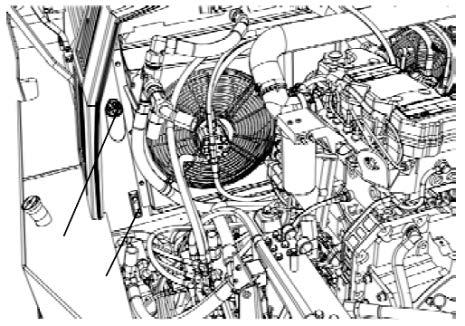
Check if the master switch is on. The master switch is located in the electric device compartment (1) on the right side of the machine.
After the daily use of the roller, the master switch shall be turned off. It prevents the machine to be turned on accidentally and protects the electronic devices.
If the main battery switch is closed, the engine hood shall be opened during the operation to make it possible to reach in an emergency.
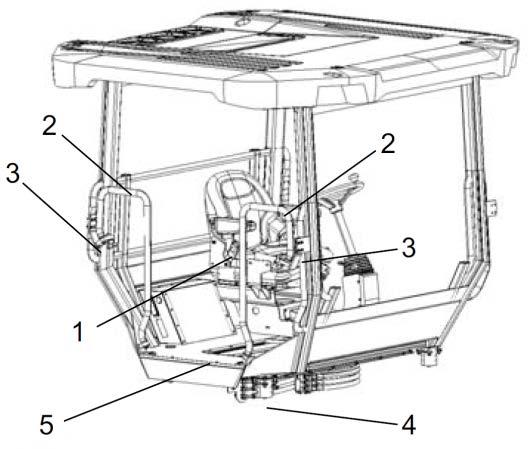
The control and operation unit
The control and operation unit has three adjustment options: transverse travel, rotation and steering column angle.
For transverse travel, raise the inner lever (1). The transverse travel brake will be released.
For rotation, raise the outer lever (2). Make sure the control unit is in the correct position before operating the machine.
For steering column angle, release the locking lever (3). Fix it again in the new position.
To adjust the operator's seat, refer to the next section.
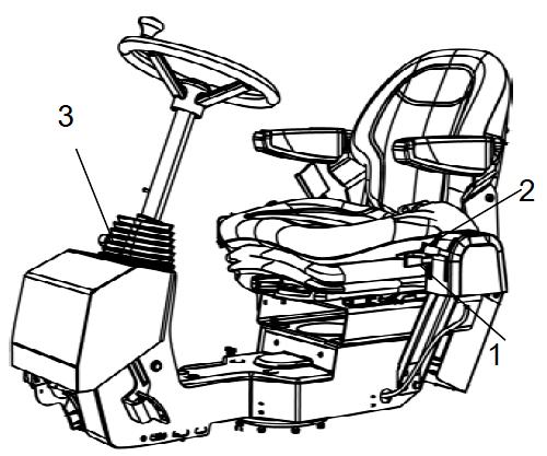
Perform all the control and operation unit adjustments when the machine is stationary.
Before starting your work shift and operating the machine, make sure the seat and the steering column are locked and never release the side travel if you are on a slope.
Operation - Before starting
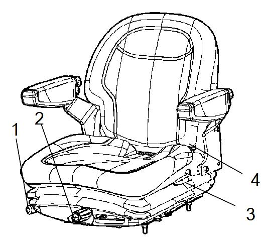
Standard operator's seat - adjustment
Adjust the operator's seat so all the controls are within easy reach and the machine operation is comfortable.
(1) Length adjustment.
(2) Weight adjustment.
(3) Back support adjustment.
(4) Seat belt.
ALWAYS make sure the seat is locked before starting the operation.
Always use the seat belt (4).
Comfort operator's seat (option) - adjustment
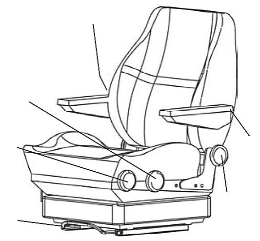
Adjust the operator's seat so all the controls are within easy reach and the machine operation is comfortable.
(1)
(2)
(3)
(4)
(5)
(6) ength adjustment. eight adjustment. eat-cushion inclination. ack support inclination. rmrest inclination. umbar support adjustment.
(7) Seat belt.
View
Before starting the engine, make sure that the view around the machine is unobstructed.
All the cab windows shall be clean and the rear view mirrors adjusted for a good rear view.
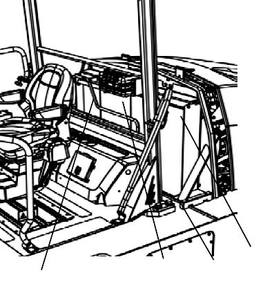
Operator position
If a ROPS (Roll Over Protective Structure) or a cab is fitted to the roller, always use the seat belt (1) and wear a protective helmet.
Always replace the seat belt for a new one if the previous show signs of wear or has been subjected to a huge impact.
The safety railings (2) around the operator's station are adjustable both in the inner and outer positions. Retract them when driving close to walls or other side obstacles.
Release the locking knob (3) and adjust and lock the railings in the desired position.
Make sure the anti-slip protections (4) of the platform are in good condition and replace them for new ones if they are worn.
If the machine is fitted with a cab, make sure the door is always closed when in motion.
Interlock
The roller is equipped with Interlock.
The Diesel engine turns off after 4 seconds if the operator leaves the seat when the machine is moving forward/backward. If the machine is in neutral position when the operator leaves the seat, a horn is sound until the parking brake is activated.
If the parking brake is activated, the Diesel engine will not stop, but the engine will be automatically turned off if, by any reasons, the transmission is not in the neutral position when the operator is not seated in his place.
Sit down for all operations!
Starting Screen - Control
Sit down for all operations.
Turn the ignition key (1) to the position I and the initial screen is shown in the Control panel (2).

Check if the voltmeter (3) appoints at least 24 volt and if the fuel (4) and water (5) levels show a percentage value.
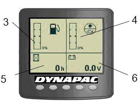
The hourmeter (6) records and shows the total quantity of the engine working hours.
Starting the engine
Make sure the emergency stop system (2) is off (upper position) and the parking brake is on.
The forward/reverse lever (1) shall be in the neutral position. The Diesel engine cannot be started if the lever is not in this position.
When sitting on the operator's seat, turn the ignition key (3) to the right (the first position I) and then to the start position. Release the switch as soon as the engine starts.

Do not try to run the start engine for too long (max. 30 seconds). If it does not work, wait 60 seconds to try again.
Let the engine idle for a few minutes or more if the environment temperature is below 50 F (10º C).
When the engine is running indoors, make sure if there is proper ventilation to extract the exhaust gases.
Operation
Display and button set
The parking brake symbol is shown when the parking brake is activated.
= Low speed.
= Automatic water control (AWC). The sprinkling is activated when the forward/backward lever is in the neutral position.
= Tire pressure.
= Sprinkler activation for edge cutter.
= High/low speed mode (in the center of the screen).
= Alarm display, see the table below for information.
Alarm descriptions
SYMBOL DESCRIPTION FUNCTION
Warning lamp, hydraulic oil filter
Warning lamp, air filter
Warning lamp, battery charging
Warning lamp, engine temperature
Warning lamp, hydraulic oil temperature
If the lamp is lit with the engine in maximum rpm, it shall be necessary to replace the hydraulic oil filter.
If the lamp is lit with the engine in maximum rpm, it shall be necessary to clean or replace the air filter.
If the lamp is lit with the engine running, the alternator is not charging. Stop the engine and find the fault.
If the lamp is lit it means the engine is too hot. Stop IMMEDIATELY the engine and find the fault. Refer to the engine manual.
If the lamp is lit it means the hydraulic oil is too hot. Do not operate the roller. Cool the oil making the engine run in idle and locate the fault.
Operating the roller
Under no circumstances the machine shall be operated away from the ground. The operator shall be seated inside the machine during the operation.

Make sure the areas at the front and behind the machine are free.
1. Select the maximum gear the machine will operate. To activate the operation speed, use the throttle on the right side of the steering column.
2. Make sure the steering is working normally by turning the steering wheel to the left and to the right once with the roller stationary.
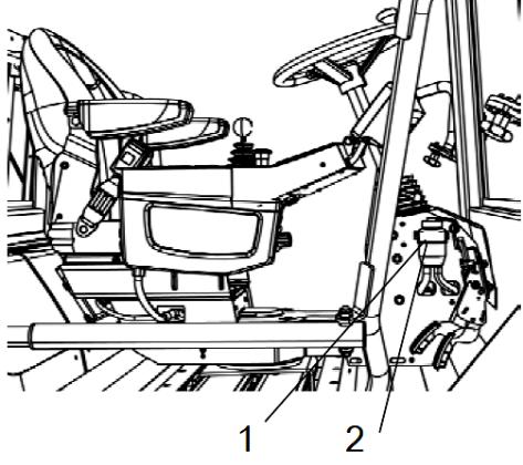
3. When compacting asphalts, do not forget to activate the sprinkler system (1) or (2).
Release the parking brake button (5) by sliding the red lock on the button backwards and changing the lever position. Remember that the machine can roll if you are on a slope.
4. Activate the low speed (3).
5. Move the forward/backward lever (4) carefully to any direction you desire.
6. Increase or decrease the machine speed using the throttle control.
Make sure the parking brake (5) is working correctly by activating it and moving the forward/backward lever (4) to the F or R position. Keep the brake test button pressed. This way, when you throttle the machine, it will not move.
Edge cutter (option)
To activate the edge cutter, the machine must be in low speed.
When the side panel button (1) is pressed with the machine in low speed, a hydraulic piston lowers down the edge cutter to the ground.
The tool can also be lifted if the machine is in the transport position.
A bypass valve prevents the hydraulic system being overloaded.
To prevent asphalt sticking to the edge cutter, the operator shall use a separate sprinkler system. It is operated by a switch (2). The water is supplied on the main tank and it is the same used in the standard sprinkler system.
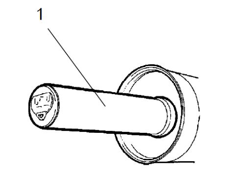
Tire pressure adjustment (option)
The operator can vary the pressure during the operation with the tire air pressure control. It can be variable adjusted with the keys (2) and (3) on the keypad, within the interval from 240 kPa to 830 kPa (35 to 120 PSI) and can be reduced with the key (3). The tire pressure level is shown in the lower left corner, on the Display (1).
When the tire pressure is at the maximum level (830 kPa) or at the minimum level (240 kPa), it will not be possible to increase/decrease the pressure.
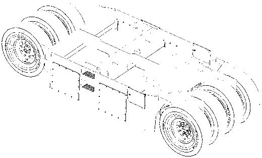
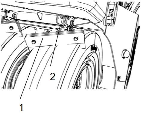
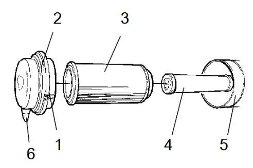
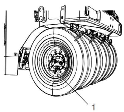
Coconut mats (option)
To apply the coconut mats (1) on the wheels, follow the instructions below:
- Hold and lift the handle in the middle of the scraper holder (2).
- Make sure the lock pin (4) releases properly from the locking hook (3) and allow the scraper to rest against the tires in the working position.
To release the coconut mats:
- Hold and lift the handle in the middle of the scraper holder (2).
- Make sure the lock pin (4) fits well in the locking hook (3).
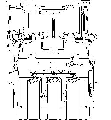
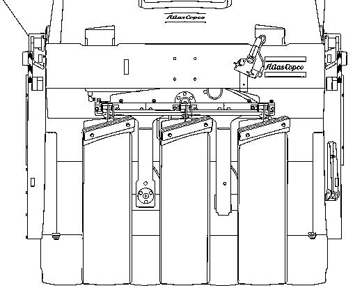
Ballast box
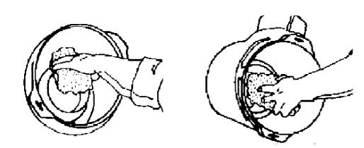
Water and wet sand ballast
Remove the top covers (1) and side upper covers (3) and fill with water and sand through this opening.
Keep the side lower covers (2) closed during the water filling.
Do not remove the draining plugs (4) because the water may leak when the ballast is filled with it.
Fill the ballast box, when necessary, with gravel, sand and steel.
The water shall be added when it is filled with sand, so it can fill all the spaces between the ballast.
When using the roller with mixed ballast, start using the steel objects available, and then add the requisite amount of sand and water.
Distribute the ballast evenly.
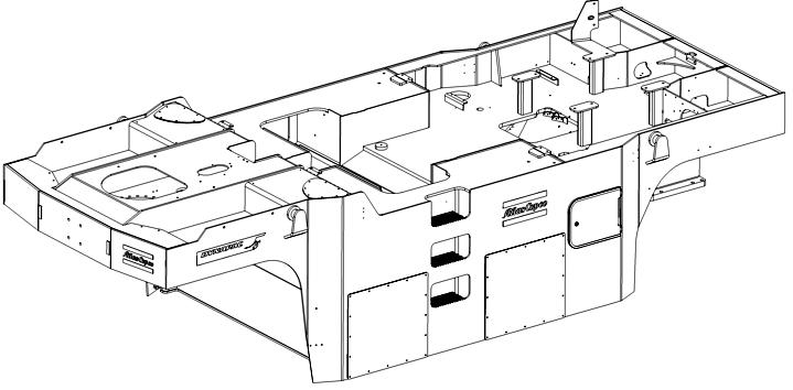
Removable steel ballasts
The CP2100/CP2100W roller uses an innovative and patented system of steel ballasts, which can be removed and installed easily and quickly:
1. With the ballast box drained (without water and/or sand), remove four side covers (1) from the ballast box.
2. Unscrew the nuts and counternuts (2) and four lower bolts (3) of the bedplate in the steel ballasts. Remove the bedplate (4) off the ballasts assembly.
3. Install or remove the ballasts, according to the necessity, using the forks from a standard forklift. The ballasts grooves (5) were projected so the forklift forks fit perfectly and to easy their removal, installation and transport
4. After installing or removing the ballasts in the box, mount the bedplate, performing the reversal steps used to remove them.
Distribute the steel ballast evenly in the box.
Operation
Ground pressure (driving)
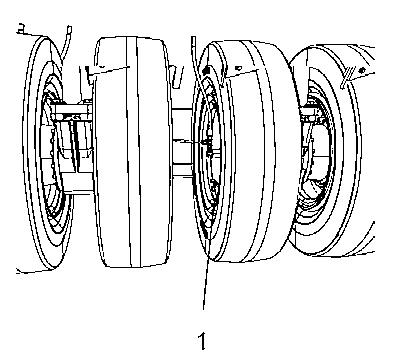
The tire contact surface can be changed by means of tire pressure.
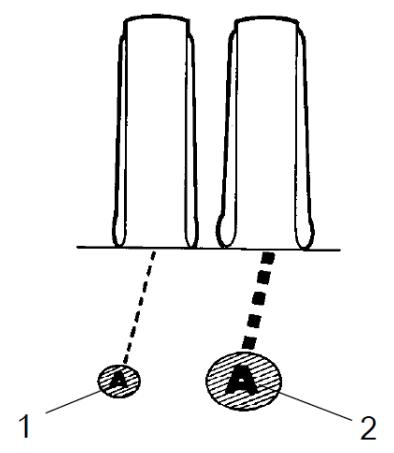
The high pressure on the tires provides a smaller contact surface (1) and the low pressure on the tire provides a larger contact surface (2).
The contact surface with the ground is very important for the compaction result. The total weight divided by the quantity of tires provides the correct pressure for the wheel, according to the following table.
Ground pressure
Operation
Low tire pressure – 240 kPa (34,8 PSI)
The lower the tires pressure, the lower the pressure on the contact surface, due to the larger surface area.
Normal tire pressure – 480 kPa (69,6 PSI)
Used for degradation session.
High tire pressure – 830 kPa (120,4 PSI)
The higher the tires pressure, the higher the pressure on the contact surface, due to the smaller surface area.
Interlock/Emergency Stop/Parking Brake
The interlock, emergency stop and parking brake shall be checked daily before starting the machine. To check if the emergency stop and interlock are working correctly, it is necessary to turn on and off the machine.
To check if the Interlock works correctly, the operator shall rise from the seat with the roller moving forwards and backwards (perform the test in both ways). The operator must hold the steering wheel firmly and be ready for a sudden stop. The alarm will be activated and after 4 seconds the engine will turn off and the brakes will be activated.
To check if the emergency stop works correctly, the operator shall press the corresponding button with the roller moving forwards and backwards (perform the test in both ways). Next, the operator must hold the steering wheel firmly and be ready for a sudden stop. The engine will be turned off and the brakes will be activated.
To check if the parking brake works correctly, it shall be activated with the roller moving forwards and backwards (perform the test in both ways). The operator shall hold the steering wheel and be ready for a sudden stop when it is activated. The engine does not turn off.
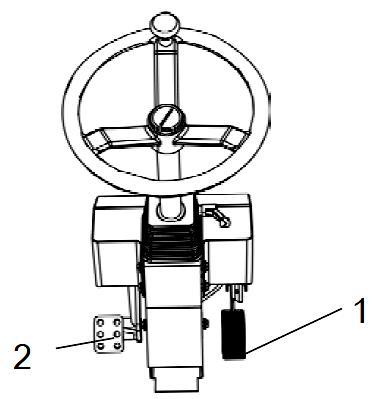
Normal braking
Release the throttle control (1) and press the brake pedal (2).
Emergency braking
The brake pedal is normally used to brake.

For emergency braking, press the emergency stop button (1), hold the steering wheel and be ready for a sudden stop. The engine stops.
The Diesel engine will be turned off and it must be turned on again, if necessary.
When starting the engine after an emergency stop, the forward/backward lever shall be in the neutral position and the parking brake shall be on.
Turning off the engine
Allow the engine to cool down in low idle for a few minutes.
Check if the Display (1) shows any indication of faults. Turn off all the lights and other electric functions.
Press the parking brake switch (3).
Turn the ignition key (2) to the left to turn it off.
Fit and fix the cover of the instruments panel over the screen and the upper part of the control box (on rollers without cab).
Chocking the wheels
Never leave the roller and let it with the engine running unless the parking brake is activated.
Make sure the machine is parked in a safe area, without traffic. Chock the wheels when parking on slopes.
In extremely cold weather, some components may freeze. Drain the water tanks and pipings.

Master switch
At the end of the working shift, turn off the battery master switch (1) and remove the handle.
This will prevent the battery discharging and will also make it difficult to start and drive the machine if unauthorized people try to use it. Close and lock the maintenance covers and doors.
Long-term storage
For long-term storage (more than a month) follow the instructions below:
These measures are valid for storage for a period of up to 6 months.
Before starting the machine again, the points stated below shall be performed before parking and store the roller.
Wash the machine and touch up the painting finishing to prevent rusting. Use anti-rust agents on the exposed parts and lubricate carefully the machine, besides applying grease to unpainted surfaces.
Engine
Refer to the manufacturer information in the engine instruction manual supplied with the roller.
Battery
Remove the batteries from the roller, clean their outside parts and recharge them once a month.
Air cleaner, exhaust pipe
Close the air tube (refer to the sections "Every 50 Hours of Operation" and "Every 1,000 Hours of Operation") or the respective intake opening with plastic or tape. Also cover the exhaust pipe opening with sealing material to avoid moisture entering in the engine.
Water distribution system
Drain all the water in the water tank and all the hoses. Also drain the filter housing and the water pump and remove all the sprinkler nozzles.
Refer to the Maintenance section to obtain further information about water draining.
Fuel tank
Fill the fuel tank completely to prevent condensation.
Hydraulic oil reservoir
Fill the hydraulic reservoir until the uppermost level mark (refer to the section "Every 10 Hours of Operation").
Tires
Make sure the tires pressure is at least 200 kPa (29 PSI).
Place supports under the chassis so that the tires are not overloaded.
Steering cylinder, hinges, etc.
Grease the steering cylinder plunger spindle to preserve it.
Also lubricate the hingers on the engine compartment and cab doors.
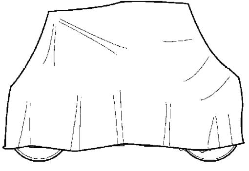
Hoods, tarpaulin
Lower the instruments hood/covering over the instrument panel.
Cover the entire roller with a tarpaulin. It shall have a gap between it and the ground.
If possible, store the machine indoors and preferably in a place with regular temperature.
When stopping and parking the equipment, always apply the parking brake.
As a precaution measure, chock the roller tires when parking on slopes and turn off the engine.
To prevent accidents, when parking on slopes, stop transversally to the road towards the slope.
Never leave the roller with the engine running. Before leaving it, apply the emergency/parking brake.
Make sure the roller is parked in a safe place and that it is not obstructing the traffic.
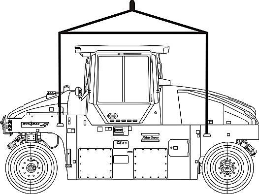
Lifting Lifting the roller
Make sure the front wheels are parallel with the frame before lifting the roller.
Make sure the hooks are safely placed in the lifting eyes. The equipment shall only be lifted by the proper lifting eyes.
Always use cables and steel chains according to the safety norms and make sure there are no worn components and that parts are not damaged during the lifting.
The machine's gross weight is specified in the hoisting plate (1). Refer also to the Technical Specifications.
Do not go under or next to the machine when it is being lifted.
Make sure the lifting hooks are safely connected to the machine. Check the machine gross weight and the compatibility of the lifting equipment.
Lifting the roller with a jack
The machine's gross weight is specified in the hoisting plate (1). Refer also to the Technical Specifications.
Lifting devices such as a jack (2) or equivalents must be dimensioned according to the safety regulations for lifting devices.
Do not go under or next to the machine when it is being lifted. Also check if the lifting device is fixed and secure in its position, and at a steady level and surface.
The roller shall only be lifted with a jack or similar if it is correctly fitted in the lifting eyes. The frame is reinforced in these points to support the tension. Lifting at any other place can result in damage to the machine or personal injury to the operator.
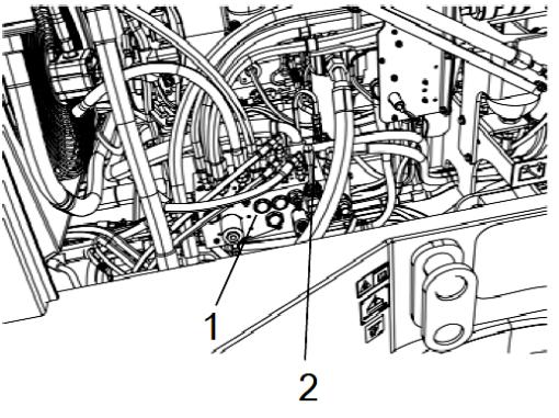
Towing
Short distance towing with the engine running
The roller can be moved up to 984 feet (300 meters), according to the following instructions:
To tow the machine, use the same lifting points.
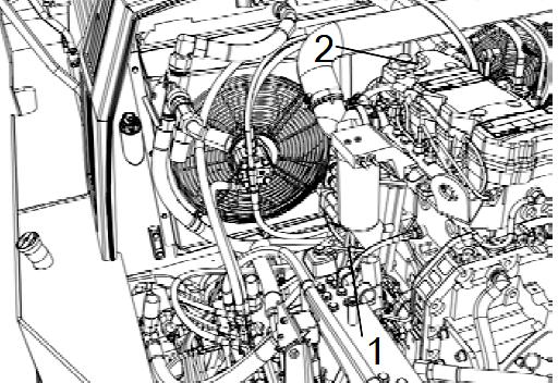
1. Park the roller on a flat and safe place. If necessary, chock the tires.
2. Open the hood and check if the propulsion pump is accessible.
3. On the pump, there are two by-pass valves (1) (hexagonal bolts) which should be turned three turns anticlockwise to put the whole system in the by-pass mode, which means that the A and B sides of the pump are freely connected to the pressure side. This function allows the machine to be moved without the drive shaft rotating.
4. Start the Diesel engine and run it in idle.
5. Move the forward/backward lever in one of the two positions. If it is in a neutral position, the hydraulic engine brakes are activated.

6. The roller can be towed and even steered now, if the steering system is working.
7. To leave the by-pass mode, turn both valves (1) three times to the right.
The machine must not be moved in a speed higher than 5 km/h and over 984 feet (300 meters). If it happens, there are risks of damage in the transmission system. Make sure the towing valves are reseted (turning them three times to the right) after the towing.
Towing
Short distance towing with the engine inoperative
As a safety measure, chock the wheels to prevent the machine to move when the brakes are hydraulically disengaged.
The roller can be moved up to 984 feet (300 meters), according to the following instructions:
1. Park the roller on a flat and safe place.
2. Open the hood and check if the propulsion pump is accessible.
3. On the pump, there are two by-pass valves (1) (hexagonal bolts) which should be turned three turns anticlockwise to put the whole system in the by-pass mode, which means that the A and B sides of the pump are freely connected to the pressure side. This function allows the machine to be moved without the drive shaft rotating.
4. The brake release pump is at the right side of the engine compartment.
5. Pump with the arm (3) until the brakes are released.
6. So the brake release pressure is quickly drained, turn on the start engine for a few seconds.
7. If you cannot start it, turn the towing valve four times to the left (remember always to turn it four times later to the right).
8. To disconnect the by-pass mode, loose the hexagon bolts turning them three times to the right.
9. This way the roller can be towed.
The machine must not be moved in a speed higher than 5 km/h and over 984 feet (300 meters). If it happens, there are risks of damage in the transmission system. Make sure the towing valves are reseted (turning them three times to the right) after the towing.
Towing the roller
When towing, the roller shall be braked by the towing vehicle. Always use a towing bar, because the machine cannot brake.
The roller must be towed slowly and must not be moved in a speed higher than 5 km/h and over 984 feet (300 meters).
During the roller towing, its devices shall be connected in both lifting holes.
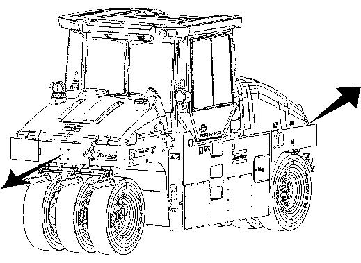
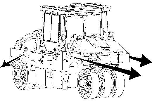
The pulling forces shall act to the machine's longitudinal axis, as illustrated in the figure. Refer to the table below to know the maximum pulling force allowed for this machine model:
Trailer eye (option)
The roller can be equipped with a trailer eye. It shall only be used for towing objects weighing no more than 4,000 kg.
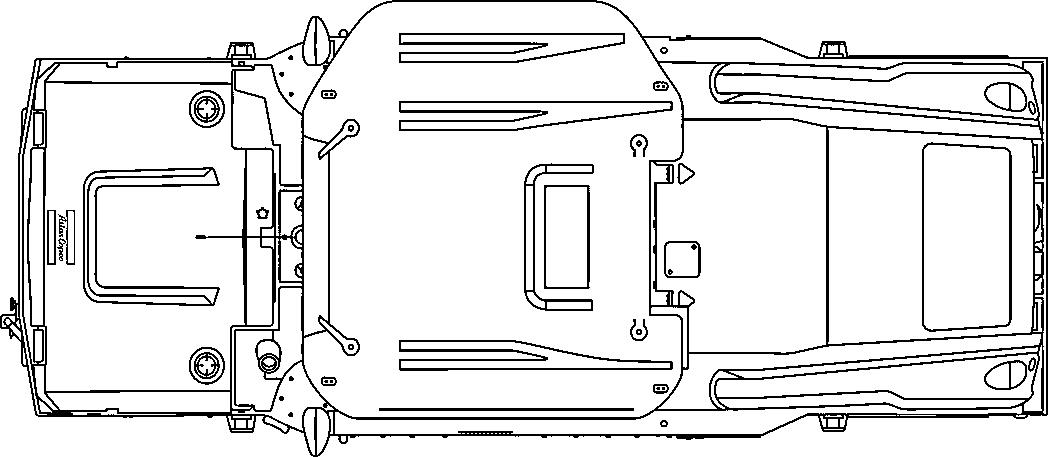
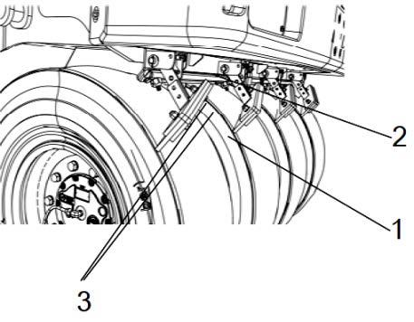
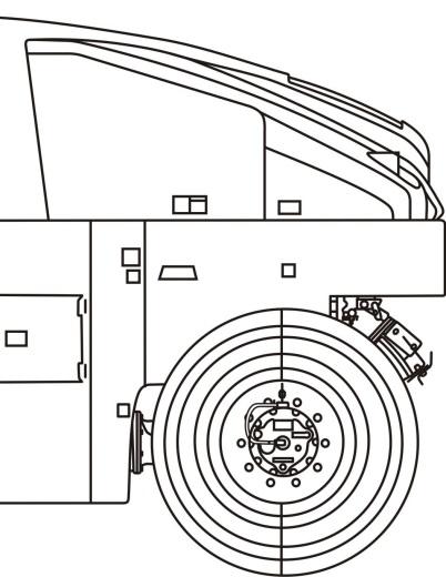
Transport Preparing the roller for transport
Apply the parking brake and make sure the machine is in the neutral position, that is, that the tires are pointing forwards.
Chock (1) the tires in an angle of 37º and at a minimum height of 9,9 inches (25 cm). They should be chocked both forwards and backwards.
Chock under the frame (2) to ensure that the chains remain tensioned if the air goes out of the tires. Block up the machine according to the figure.
Secure the roller with chains in all four corners. The attachment points are shown in the safety decals. Put the chains in symmetrical pairs, crossing each other.
Make sure the chains, supports and attachments of the transport vehicle are approved and have the proper tension to perform the fitting and locking. Check regularly if the chains are not slack.
Operation instructions - Overview
Operation instructions - Overview
Follow the safety instructions specified in the Safety Manual.
● Make sure all the MAINTENANCE INSTRUCTIONS were carried out. For further information, refer to the Maintenance section in this manual.
● Turn on the battery switch.
● Move the forward/backward lever to the "P" position.
● Apply the emergency stop. The roller will always start in the High speed.
● Keep the ignition key in the "O" position.
● Start the engine and warm it.
Always check the brakes. Before starting the working shift, carry out a test in the system, and remember that if the hydraulic oil is cold, the brake distance will be longer.
When operating the roller, use carefully the forward/backward lever.
● Make sure the tires are well sprinkled, when necessary.
In an emergency, apply the emergency stop, hold well the steering wheel and be ready for a sudden stop.
● When parking: stop the engine, apply the parking brake and chock the roller tires.
● When towing: refer to the towing instructions in this manual.
● When lifting: refer to the lifting instructions in this manual.
● When transporting: refer to the transport instructions in this manual.
Preventive maintenance Introduction
It is necessary to carry out a complete maintenance so the machine can work satisfactorily and at the lowest possible costs.
The Maintenance section includes the periodic maintenance that shall be carried out on the machine.
The recommended maintenance intervals assume that the machine is being used in a normal environment and working conditions.
Delivery
The machine is tested and adjusted before leaving the plant.
The inspection shall happen in the moment it arrives to the client, following the list in the warranty document.
Any transport damage shall be immediately reported to the carrier company.
Warranty
The warranty is only valid if the inspections were carried out at the time of the delivery, as well as the maintenance inspections according to the warranty.
The warranty is not valid if there are damages due improper assistance, misuse of the machine, use of lubricants and hydraulic oils not specified in the manual or if other adjustments were made without the proper authorization.
Warning symbols
WARNING! Damage to the machine or its parts.
CAUTION! Risk of death or injures.
ENGINE OIL
Preventive maintenance - Symbols and lubricants
Preventive maintenance - Symbols and lubricants
Always use high quality lubricants and in the amounts required. Too much grease or lubricant oil can cause overheating and premature wear.
Room temperature: 5 F to 122 F (-15ºC to 50ºC)
ENGINE TIER III
Shell Rimula R4 L 15W -40 or equivalent.
ENGINE TIER IV
Shell Helix Ultra 5W -40 or equivalent.
HYDRAULIC OIL
Room temperature: 5 F to 122 F (-15ºC to 50ºC)
Room temperature: above 122 F (50ºC)
BIOLOGICAL HYDRAULIC OIL
When leaving the plant, the machine may be filled with biologically degradable oil. When replacing or filling with oil, use the same type of oil used previously.
GREASE
FUEL
Refer to the engine manual instructions.
COOLANT
Antifreeze protection effective down to34.6 F (-37ºC). 50/50 mixed (clean water + coolant additive).
TRANSMISSION OIL
Shell Tellus V68 or equivalent.
Shell Tellus V100 or equivalent.
PANOLIN HLP Synth 46 (www.panolin.com)
Shell Retinax LX2 or equivalent.
-
GlycoShell/Carcoolant 774C or equivalent.
Shell Spirax S2 ALS 85W -140 API GL-5 or equivalent.
For room temperatures extremely high or low, other lubricants shall be applied. Refer to the chapter "Special Instructions" or contact DYNAPAC.
Preventive maintenance - Symbols and lubricants
Engine, oil level
Engine, oil filter
Hydraulic fluid, level
Air filter
Hydraulic fluid, filter
Transmission, oil level
Fuel filter
Battery
Coolant level
Lubricating oil
Air pressure
Sprinkler
Sprinkler water
Recycling
The roller can use 16 ballast blocks inside the frame. Each block is 1,102 lb (500 kg) and is used individually. Eight of them are in the front part and eight are in the rear part, so use a proper combination to obtain the maximum of the ballast.
The roller working weight consists of the machine weight and the ballast weight. Thicker layers demand a heavier machine for compacting, and thinner layers do not need a machine that heavy.
Filling Volumes
Specifications
Specifications (cont.) – Working capacity
COMPACTION DATA
Load on the tires:
- Without ballast 1,400 kg
- With wet sand ballast 2,100 kg
- With the ballast at its max. 3,000 kg
Torque
Torque for oiled bolts tightened with a torque wrench.
Torque (cont.)
Hydraulic system
Specifications
Specifications (cont.)
Air conditioning (option)
The system described in this manual is the ACC (Automatic Climate Control), that is, a system which maintains the set temperature in the cab provided that all the windows and doors are kept closed.
Coolant designation: R134a
Coolant weight when full: 1,000 g (2.20 lbs).
Engines
ENGINE
Manufacturer and model Cummins QSB 3.3 TIER 3
Power (SAE J1995) 99 HP (74 kW) @ 2,200 rpm
ENGINE
Manufacturer and model Cummins QSB 3.8 TIER 4
Power (SAE J1995)
Lamps (when installed)
HP (89 kW) @ 2,200 rpm
Maintenance and lubrication points
Maintenance and lubrication points
Read carefully this manual section before carrying out any maintenance or lubrication on the machine.
Always check the areas around and under the equipment. It is an easy way to detect earlier leakages and possible damages.

Scheduled maintenance and lubrication
Scheduled maintenance and lubrication
Maintenance and lubrication procedures
The maintenance and lubrication shall be carried out first based on the working hours. When they cannot be considered, use the periods, like daily, weekly, etc.
Always clean around the covers, plugs, grease nipples or hoods before open or apply grease to them.
Respect and follow the engine manufacturer instructions. For further information, refer to the Engine Manual.
Notes
WEEKLY (after the first 50 hours of operation) POSITION
IN THE FIGURE ACTION
Notes
1, 2 Replace the Diesel engine oil and the oil filter Refer to the engine manual instructions.
10 Check and replace the main air filter Refer to the engine manual instructions.
10 Check and replace the secondary air filter Refer to the engine manual instructions.
3 Replace the engine fuel filter Refer to the engine manual instructions.
4 Replace the hydraulic oil filters
20 Lubricate the lower pivot bearing
21 Lubricate the upper pivot bearing
23 Replace the wheel gear oil
WEEKLY (Every 50 hours of operation) POSITION
IN THE FIGURE
ACTION NOTES
- Check the engine air intake system Refer to the engine manual instructions.
- Check the tires air pressure
- Retighten the wheel nuts
10 Check and clean the engine air filter elements Replace them, if necessary
- Drain the fuel pre-filter Refer to the engine manual instructions.
18 Check the air conditioning When equipped (option)
- Clean the air conditioning
19 Check and lubricate the edge cutter When equipped (option) 20 Lubricate the lower pivot bearing 21
MONTHLY (Every 250 hours of operation)
POSITION IN THE FIGURE ACTION
Notes
1, 2 Replace the Diesel engine oil and the oil filter Refer to the engine manual instructions.
8 Check and clean the hydraulic water and Diesel engine water coolers.
If necessary
18 Check the air conditioning When equipped (option)
16 Check the batteries
Lubricate the pilot and link bearings
20 Lubricate the lower pivot bearing
21 the upper pivot bearing
Replace the air dryer filter
Machine equipped with AOR
EVERY THREE MONTHS (Every 500 hours of operation)
POSITION IN THE FIGURE ACTION NOTES
3 Replace the Diesel engine fuel filter Refer to the engine manual instructions.
- Replace the Diesel engine pre-filter Refer to the engine manual instructions.
- Check the bolted joints
7 Check the hydraulic oil tank cover 15
Daily (Every 10 hours of operation)
Park the roller on a level surface.
When checking and adjusting the machine, always turn off the engine and make sure the forward/backward lever is in the neutral position.
When the engine is off in enclosed places, make sure there is a good ventilation, to prevent carbon monoxide poisoning.
Check the Diesel engine oil level
The oil dipstick is under the oil filling plug (1), on the left side of the engine.
Be careful with hot engine parts and also with the cooler when removing the oil dipstick. There is risk of burns.
1. Remove the dipstick (2) and check if the oil level is between the upper and lower parts. For further information, refer to the Engine Manual instructions.
Check the engine coolant
The expansion tank is placed in the center, between the operator platform and the engine compartment. To access the expansion tank (3), remove both retaining bolts (1) and also the protective plate (2).
Check if the coolant level is between the MAX and MIN marks in the expansion tank (3). If necessary, remove the tank hood and fill the level.
NEVER open the expansion tank cap if the engine is still hot and always use protective gloves and goggles.
When filling with coolant, always use a mixed solution with 50% of water and 50% of additive. Refer to the lubricant specifications in this manual and in the engine instructions manual.
Check the hydraulic oil level
1. Park the roller on a level ground and turn off the engine.
2. Check the hydraulic oil reservoir sight glass (1) located on the right side of the machine.
3. If the oil level is 2 cm below the glass upper line, fill with the recommended hydraulic oil.
Use only hydraulic oil recommended by DYNAPAC.
Filling the fuel tank
Never fill the engine when it is working. Do not smoke and avoid spilling fuel.
The filling nozzle and the tank cap are in the front of the operator platform, in the left side of the machine.
Check the fuel tank daily before starting the operation or fuel the tank when the work is done.
Unscrew the tank cap (1) and check up to the lower edge of the filler pipe.
The tank capacity is of 55.4 gal (210 liters) of fuel. For further information about the fuel grade, refer to the Engine Manual.
Before filling, stop the machine on a safe place with level surface, turn off the engine and ground the filling pipe, putting it in contact with the frame in a non-insulated place.
When filling, keep the pump nozzle in contact with the filling pipe. Always use fuel recommended by DYNAPAC
Using adulterated, contaminated, dirty or bad quality fuel damages the injection system and engine components. The repairs due to the conditions above are NOT covered by the warranty.
Fill the water tanks
There are two filling caps above the water tank (1).
Unscrew the tank cap and fill with clean water. Do not replace the filter.
1. Fill the tank; it holds 110 gal. (415 liters).
Only recommended additive: small quantity of environmentally-friendly antifreeze.
Check the sprinkler system
Fill the tank with emulsion fluid, e.g. water mixed with 2% of cutting fluid.
Check if the sprinkler injectors (3) are not blocked, and if necessary, clean them, as well as the filter.
Check periodically if there is excessive wear on the roller tires.
Do not add flammable fluids or those which are hazardous to the environment in the emulsion tank.

Clean the sprinkler injector
Dismantle the blocked nozzle by hand (1).
Use compressed air to clean the nozzle (1) and the strainer (2). It is also possible to use the spare parts and to clean the blocked ones later on.
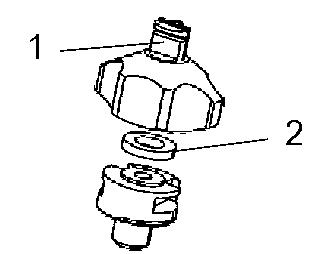
After checking and cleaning, turn on the system and inspect if it is working correctly.
Use protective goggles when working with compressed air.
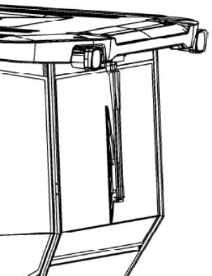
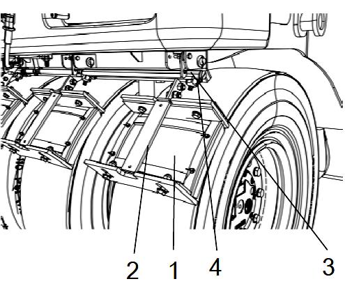
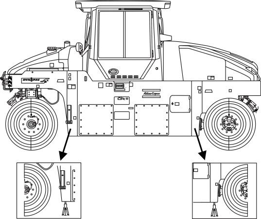
Adjust the scrapers
Make sure the scrapers and tires are in good operation conditions, otherwise, replace them.
If the scraper's wear is uneven, unscrew the adjusting bolt (3) in the back of the scraper attachment.
Pull down the blade (1) until it is leveled with the tire. After the adjustment, tighten the screws again (3).
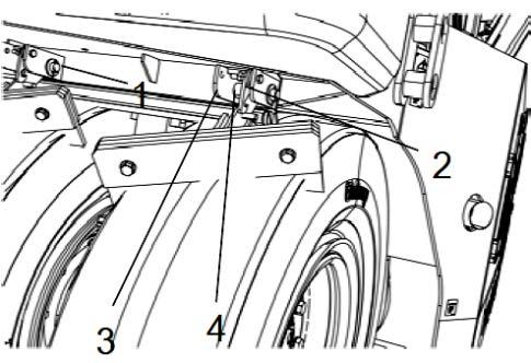
The scrapers shall be adjusted on the tires during the transport.
To do it, lift up the scraper blades (1) and make sure they are fixed at this position by the locking hooks (2).
To lower down the scrapers, raise the scraper blade (1) firmly while pressing the locking hook (2).
The scrapers can be easily removed for cleaning and inspection.
1. First, fix the scraper in the locking hook (3) at the scraper attachment (4) to prevent the scraper to fall onto the ground.
2. Remove the pin (1) on the hook axle removing the hairpins (2) on both sides of the pin. Grip the hook axle up and pull it straight out.
To put the scraper back after the inspection, it shall be initially fit on the locking hook before the up hook is fitted in the right position.
Refit the pin (3) in the right position and make sure it is well secured by the attachment (4).
Check the brakes oil level
Check daily if the oil level is within the max. and min. marks. Open the brake oil tank (1) under the plastic cap, on the right side of the steering column.
Next, fill with hydraulic oil up to the tank's maximum level, if it is under the min. mark.
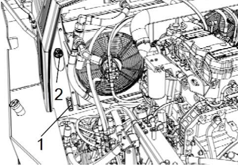
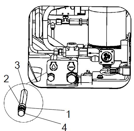
Clean the coarse filter
The coarse filter is inside the frame' upper compartment, on the right side of the machine.
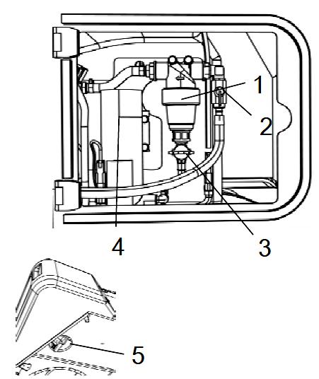
To clean the coarse filter (1), open the drain cock (2) of the filter and let the dirt run out.
If necessary, close the cock (3) and clean the filter and its housing. Check if the rubber gasket of the filter housing is in intact.
After the cleaning and inspection, put again all the components on their right places and start the system to check if it works correctly.
Another drain cock (5) is under the water tank, on the left side of the front of the frame. It can be used to drain the water tank and the pumping system.
It is also possible to install an extra pump if the standard fails to work.
To drain the complete sprinkler system, refer to "Draining the sprinkler system", in the section "Maintenance - Every 2,000 hours".
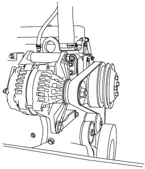
Check the alternator belt tension
Use the pressure or Burroughs type gauge to check the belt tension.
• The new belt tension shall be 200 lb (890 N).
• The old belt tension shall be 80 – 160 lb (360 – 710 N).
NOTE: The belt is considered used after 10 or more minutes of use.
NOTE: This procedure is not applied in belt automatic tensioners.
If the used belt tension is under the minimum value, tighten it to the maximum allowed value for used belts.
Drain the fuel filter
To drain the fuel filter, follow the instructions below:
1. Unscrew the drain plug (1), in the bottom of the filter.
2. With the hand-operated secondary pump (2), make sure all the sediments were removed. For further information, refer to the Engine Manual instructions.
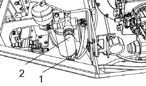
3. When only clean fuel is coming out of the filter, close the drain plug.
TAKE CARE OF THE ENVIRONMENT: All the used oil shall be properly stored for subsequent disposal. Do not dispose of oil on the ground, sewage system or other place which can harm the environment.
Weekly (Every 50 hours of operation)
Park the roller on a level surface.
When checking and adjusting the machine, always turn off the engine and make sure the forward/backward lever is in the neutral position.
When the engine is off in enclosed places, make sure there is a good ventilation, to prevent carbon monoxide poisoning.
Replace the Diesel engine oil
The engine oil drain plug is on the rear of the machine, on the right side. Its access can be found when opening the panel in front of the exhaustion duct.
Drain the oil when the engine is still hot and put a container with minimum capacity of 3.69 gal (14 liters) under the plug.
Be extremely careful when draining the oil. Use gloves and protective goggles to prevent the hot oil getting in contact with the skin, which can cause burns.
1. Remove the hexagon nut (1), take off the hose (2) and loose the oil drain plug (3).
2. Let all the oil come out to the container and when the operation is done, fix the drain plug (3) back to its place and fit the hose (2) back again.
3. Next, tighten the hexagon nut.
TAKE CARE OF THE ENVIRONMENT: All the used oil shall be properly stored for subsequent disposal. Do not dispose of oil on the ground, sewage system or other place which can harm the environment.
Always fill with new oil. For correct grade oil information, refer to the Lubricant specifications or the Engine Manual Instructions. Fill according to the oil volume necessary to the engine. Check the dipstick to know if the volume is correct and before carrying out the operation, let the engine in idle for a few minutes and turn it off.
Replace the Diesel engine oil filter
Never perform any maintenance work under the machine while the engine is still operating. Always park the roller on a flat and safe place and chock the tires.
The oil filter (1) is on the right side of the engine compartment. Refer to the Engine Instructions Manual to obtain information about the oil filter replacement.
Check and replace the main air filter
Replace the main filter element when the corresponding warning light on the instrument panel comes on and the engine is in the maximum speed.
1. Release the clamps (1), take off the cap (2) and the main filter (3). Do not take off the backup filter (4).
2. If necessary, clean the air filter, according to this page instructions.
3. When replacing the main filter (3), put a new one in its place and fit back all the air filter components in the reverse order.
4. Check if the dust valve (6) is in good conditions and replace it, if necessary.
5. When fitting the cap, make sure the dust valve is positioned downwards.
To clean the air filter, follow the instructions below:
1. Wipe inside the cap and the filter housing.
2. Wipe also both outlet pipe surfaces, as shown in figure.
Check if the hoses clamps between the filter housing and the intake hose are tighten and if the hoses are intact. Check the entire hose system, all the way to the engine.
Check and replace the secondary air filter
Replace the backup filter when the main air filter is replaced for the third time.
To replace the backup filter for a new one, follow the instructions below:
1. Remove the old backup filter (1) from the holder, install a new on and fit the components back in the reverse order.
2. Clean the main filter, if necessary.
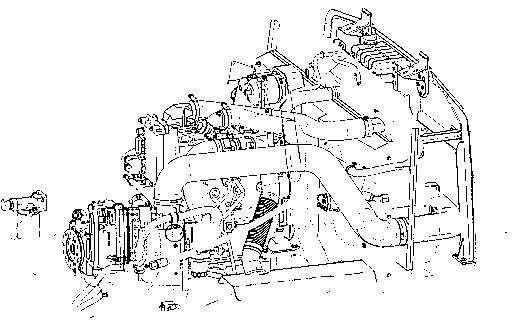
Replace the engine fuel filter
The fuel filter is located in front of the accumulators, on the left side of the engine compartment.
1. Unscrew the bottom of the filter and drain the water. Next, screw the unit back in its place.
2. Fit the fuel filter in the correct place, turn on the engine and check if the filter is well sealed.
Replace the hydraulic oil filters
The hydraulic filters are located on the left side of the engine compartment, behind the battery disconnected
TAKE CARE OF THE ENVIRONMENT: All the used oil shall be properly stored for subsequent disposal. Do not dispose of oil on the ground, sewage system or other place which can harm the environment. The filter is disposable and cannot be cleaned.
1. Open the hydraulic oil tank cap (1).
2. Clean carefully the sealed surface on the filter holder.
3. Apply a thin layer of clean hydraulic oil on the rubber gasket of the new filter.
4. Fit manually the filter, first until the filter gasket manages to reach the holder. Next, tighten it with one more turn.
5. Check the hydraulic oil level on the sight glass (2) and adjust, if necessary. Refer to the section "Every 10 Hours" to obtain further information.
6. Turn on the engine and check if the filter is well sealed.
Check the tires air pressure
To check the pressure, use an air pressure gauge. The pressure in all the tires must be the same.
To know the recommended pressure values, refer to the "Technical Specifications" section.
When replacing the tires, it is important that all of them have the same original diameter and width, otherwise they can slide into the wheel or make their installation impossible.
Lubricate the upper/lower pivot bearing
1. Lubricate the grease fitting of the upper pivot bearing (1) and the grease fitting of the lower pivot bearing (2) by operating the grease gun manually with five pump strokes.
2. Use the grease according to the lubricant specifications recommended by DYNAPAC
Replace the wheel gear oil
Be extremely careful when draining the oil. Use gloves and protective goggles to prevent the hot oil getting in contact with the skin, which can cause burns.
1. Unscrew the drain plug (1).
2. Put a container with 5.28 gal (20 liters) of capacity under the drain plug.
3. Unscrew the drain plug (1) and the filling plug (2) to evacuate the air. Allow all the oil to drain out to the container and refit the plugs.
TAKE CARE OF THE ENVIRONMENT: All the used oil shall be properly stored for subsequent disposal. Do not dispose of oil on the ground, sewage system or other place which can harm the environment.
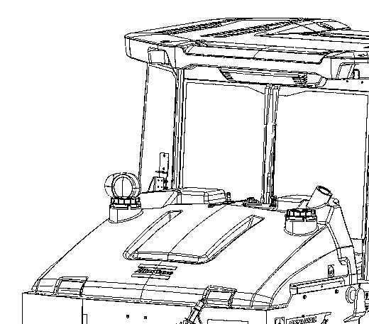
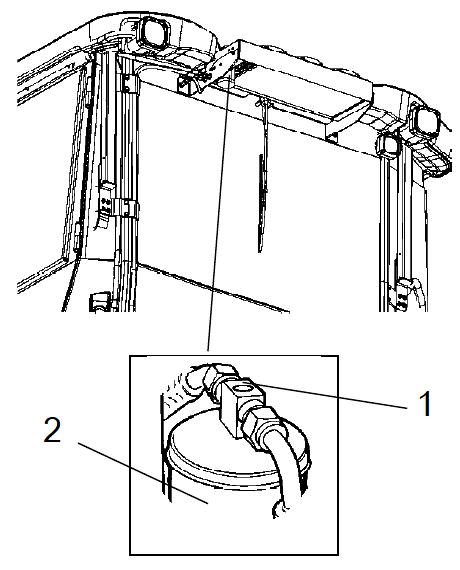
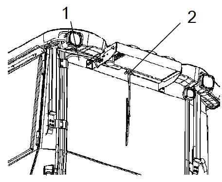
Check the air conditioning (if equipped)
Park the roller on a level surface.
When checking and adjusting the machine, always turn off the engine and make sure the forward/backward lever is in the "P" position.
With the machine working and with the aid of the sight glass (1), check if there are no visible bubbles on the drying filter.
The filter is located on the upper rear part, on the cab's roof. If there are visible bubbles, it indicates that the coolant level is too low. Turn off the air conditioning to prevent damages and fill it with coolant.
Clean the air conditioning
If there is a significant loss of cooling capacity, clean the condenser element (3), located on the rear of the cab's roof.
Check and lubricate the edge cutter (if equipped)
Refer to the Operation section to obtain more information about how to work with an edge cutter.
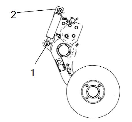
Lubricate both points indicated in the figure.
Recommended grease shall be used to lubricate it.
Lubricate all the pivot points, with 5 grease gun applications each.
Monthly (Every 250 hours of operation)
Park the roller on a level surface.
When checking and adjusting the machine, always turn off the engine and make sure the forward/backward lever is in the neutral position.
When the engine is off in enclosed places, make sure there is a good ventilation, to prevent carbon monoxide poisoning.
Replace the Diesel engine oil
The engine oil drain plug is on the rear of the machine, in the right side. Its access can be found when opening the panel in front of the exhaustion duct.
Drain the oil when the engine is still hot and put a container with minimum capacity of 3.69 gal (14 liters) under the plug.
Be extremely careful when draining the oil. Use gloves and protective goggles to prevent the hot oil getting in contact with the skin, which can cause burns.
1. Remove the hexagon nut (1), take off the hose (2) and loose the oil drain plug (3).
2. Let all the oil come out to the container and when the operation is done, fix the drain plug (3) back to its place and fit the hose (2) back again.
3. Next, tighten the hexagon nut.
TAKE CARE OF THE ENVIRONMENT: All the used oil shall be properly stored for subsequent disposal. Do not dispose of oil on the ground, sewage system or other place which can harm the environment.
Always fill with new oil. For correct grade oil information, refer to the Lubricant specifications or the Engine Manual Instructions. Fill according to the oil volume necessary to the engine. Check the dipstick to know if the volume is correct and before carrying out the operation, let the engine in idle for a few minutes and turn it off.
Replace the Diesel engine oil filter
Never perform any maintenance work under the machine while the engine is still operating. Always park the roller on a flat and safe place and chock the tires.
The oil filter (1) is on the right side of the engine compartment. Refer to the Engine Instructions Manual to obtain information about the oil filter replacement.
Check and clean the hydraulic water and Diesel engine water coolers.
1. Make sure the air flow through the coolers is unobstructed. If the cores are dirty, wash them with flowing water (with the engine cold) and blow them with compressed air.
When using compressed air, always use protective goggles.
Whenever possible, clean the cores on the opposite direction to the fan air flow. Every time you clean the core, cover the electric and electronic components.
Check the air conditioning (if equipped)
Check the coolant hoses and connections and make sure there is no sign of oil. If there is oil, maybe there is a possible leakage as well.
Check the batteries
When checking the batteries, never smoke or allow sparks or flame next to them. Usually the batteries produce explosive gases which can cause severe injuries.
The batteries are sealed and maintenance-free.
Never use open flames when checking the electrolyte level. When the alternator is being charged, an explosive gas is formed in the battery.
When removing the battery, first remove the negative pole (-). But when installing it, connect first the positive pole (+). Avoid the contact of both battery posts with metallic tools or the accidental contact between the positive post with the machine's frame, otherwise short circuits can happen.
1. Open the right cap of the equipment, where the batteries are located.
2. Clean the external caps of the batteries.
When working with batteries, protect your face and eyes using the proper equipment for individual protection and always provide the proper ventilation as well.
3. Take off the cell caps and check the electrolyte level, which must be at least 10mm above the plates. If necessary, fill the level with the battery fluid solution. If the operation room temperature is below 32 F (0ºC), allow the engine to work for a few minutes after the level is filled, otherwise the solution may freeze.
4. Check if the cell cap breather is not obstructed, and clean it, if necessary.
5. The battery posts must be kept clean and the contacts must have their cables tightened. If they are oxidized, clean them with a solution of water and sodium bicarbonate and apply a layer of petroleum jelly to prevent a new corrosion process.
TAKE CARE OF THE ENVIRONMENT: Return the used battery, according to the CONAMA 257/99 (06/30/1999) resolution. Every client or final user has the obligation to return the used battery to a sales point.
Lubricate the upper/lower pivot bearing
1. Lubricate the grease fitting of the upper pivot bearing (1) and the grease fitting of the lower pivot bearing (2) operating the grease gun manually with five pump strokes.
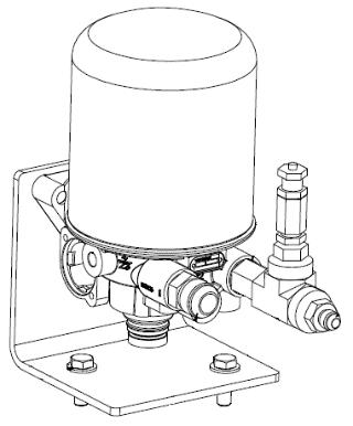
2. Use the grease according to the lubricant specifications recommended by DYNAPAC.
Replace the air dryer filter
To replace the filter, empty the compressed air and unscrew the cartridge with suitable tool Clean and grease the sealing surfaces and the fixing screw Manually screw the cartridge until there is resistance, and tighten half turn
Quarterly (Every 500 hours of operation)
Park the roller on a level surface.
When checking and adjusting the machine, always turn off the engine and make sure the forward/backward lever is in the neutral position.
When the engine is off in enclosed places, make sure there is a good ventilation, to prevent carbon monoxide poisoning.
Replace the engine fuel filter
The fuel filter is located in front of the accumulators, on the left side of the engine compartment.
1. Unscrew the bottom of the filter and drain the water. Next, screw the unit in its place again
2. Fit the fuel filter in the correct place, turn on the engine and check if the filter is well sealed.
Replace the air dryer filter
To replace the filter, empty the compressed air and unscrew the cartridge with suitable tool Clean and grease the sealing surfaces and the fixing screw Manually screw the cartridge until there is resistance, and tighten half turn
Check the hydraulic oil tank cover
To check the hydraulic oil tank cap:
1. Unscrew the tank cap and check if it’s obstructed. The air must flow freely throughout the cap in both ways.
2. If one way is obstructed, wash the filter with a small portion of Diesel oil and use compressed air until the obstruction is eliminated or replace the cap for a new one.
Always use protective goggles when working with compressed air.
Lubricate the seat bearing
Keep in mind that the chain is a vital part of the steering mechanism.
To lubricate the seat bearing:
1. Remove the cap (2) to access the grease fitting (2). Lubricate the operator's seat rotation bearing with three strokes of a hand-operated grease gun.
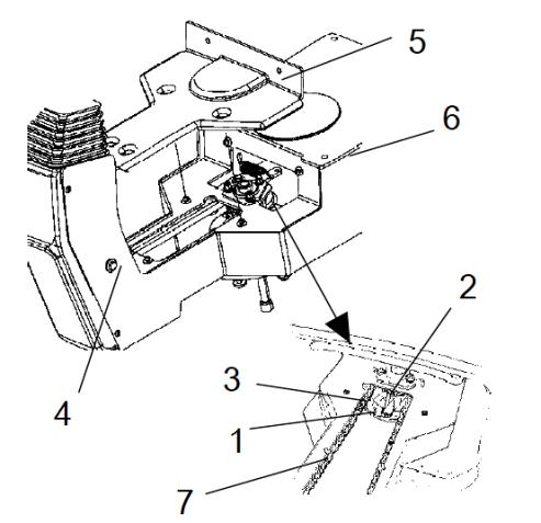
2. Clean and lubricate the chain (3) with grease between the seat and the steering column.
3. Also lubricate the slide rails (4) of the seat with grease.
4. If the chain gap is next to the sprocket wheel (5), loose the bolts (6) and move the steering column forward. Tighten the bolts and check if the chain is with the proper gap.
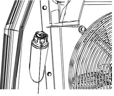
5. Do not tension the chain too tightly. It should be possible to move the chain about 0.4 inches (10 mm) to the side with a forefinger/thumb at the marking (7) in the seat frame. Fit the chain lock at the bottom.
If it is hard to move the seat, lubricate it more frequentl y than the instructions specified in this manual.
Lubricate the upper/lower pivot bearing
1. Lubricate the grease fitting of the upper pivot bearing (1) and the grease fitting of the lower pivot bearing (2) operating the grease gun manually with five pump strokes.
2. Use the grease according to the lubricant specifications recommended by DYNAPAC
Lubricate the pivot bearing
1. Lubricate each grease fitting (1) with five hand-operated strokes.
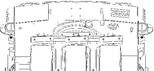
2. Use the grease according to the lubricant specifications recommended by DYNAPAC
Semiannually (Every 1,000 hours of operation)
Park the roller on a level surface.
When checking and adjusting the machine, always turn off the engine and make sure the forward/backward lever is in the neutral position.
When the engine is off in enclosed places, make sure there is a good ventilation, to prevent carbon monoxide poisoning.
Replace the main air filter
Replace the air filter (1) every 1,000 hours of operation, even if it was not cleaned 5 times. For further information about the filter's replacement, refer to the "Maintenance - Every 50 Hours of Operation" section.
If the filter is not replaced when it is obstructed, the engine will lose power and the exhaust will let the smoke black, besides the risks of damaging the engine.
Replace the secondary air filter
Replace the secondary air filter for a new one when you clean or replace the main filter for the fifth time. The secondary air filter shall not be cleaned.
To replace it for a new one, follow the instructions below:
1. Remove the old backup filter (1) from the holder, install a new one and fix the components in the reverse order used to remove them.
Replace the air dryer filter
To replace the filter, empty the compressed air and unscrew the cartridge with suitable tool. Clean and grease the sealing surfaces and the fixing screw Manually screw the cartridge until there is resistance, and tighten half turn.
Maintenance - Every 1,000 hours
Replace the hydraulic oil filters
The hydraulic filters are located on the left side of the engine compartment, behind the battery switch.
TAKE CARE OF THE ENVIRONMENT: All the used oil shall be properly stored for subsequent disposal. Do not dispose of oil on the ground, sewage system or other place which can harm the environment. The filter is disposable and cannot be cleaned.
1. Open the hydraulic oil tank cap (1).
2. Clean carefully the sealed surface on the filter holder.
3. Apply a thin layer of clean hydraulic oil on the rubber gasket of the new filter.
4. Fit manually the filter, first until the filter gasket manages to reach the holder. Next, tighten it with one more turn.
5. Check the hydraulic oil level on the sight glass (2) and adjust, if necessary. Refer to the section "Every 10 Hours" to obtain further information.
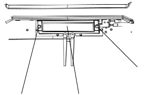
6. Turn on the engine and check if the filter is well sealed.
Replace the cab air filter
There is an air filter (1) on the left side of the cab. To replace it, follow the instructions below:
1. Open the protective cap.
2. Unscrew the bolts (2) and remove the entire holder. Remove the filter element and replace the filter for the new one.
3. If the machine works in places with excessive dust, it may be necessary to replace the filter more frequently.
Lubricate the upper/lower pivot bearing
1. Lubricate the grease fitting of the upper pivot bearing (1) and the grease fitting of the lower pivot bearing (2) operating the grease gun manually with five pump strokes.
2. Use the grease according to the lubricant specifications recommended by DYNAPAC
Replace the wheel gear oil
Be extremely careful when draining the oil. Use gloves and protective goggles to prevent the hot oil getting in contact with the skin, which can cause burns.
1. Unscrew the drain plug (1).
2. Put a container with 5.28 gal (20 liters) of capacity under the drain plug.
3. Unscrew the drain plug (1) and the filling plug (2) to evacuate the air. Allow all the oil to drain out to the container and refit the plugs.
TAKE CARE OF THE ENVIRONMENT: All the used oil shall be properly stored for subsequent disposal. Do not dispose of oil on the ground, sewage system or other place which can harm the environment.
Refill the wheel gear oil
Drive the machine until the filling plug is in the right position. The opening must be a little above the horizontal position in order to make the filling easier.
Unscrew the filling plug (1) and also the level plug (2), so the air can be released. Apply the oil only from the external part of the gears.
Fill with 2.11 gal (8 liters) of new transmission oil. Refer to the manufacturer specifications.
Drive the machine until the level plug (2) is in the horizontal position.
Check if the oil level reaches the bottom of the plug opening.
Clean and fix the plugs again.
Check the wheel gear oil level
Drive the machine until the level plug (2) is in the horizontal position.
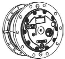
Clean the place around the level plug (2) and then unscrew it.
Check if the oil level reaches the bottom of the plug opening. If the level is low, fill with new transmission oil until it reaches the correct level. Refer to the lubricant specifications.
Clean and fix the plugs again.
Annually (Every 2,000 hours of operation)
Park the roller on a level surface.
When checking and adjusting the machine, always turn off the engine and make sure the forward/backward lever is in the neutral position.
When the engine is off in enclosed places, make sure there is a good ventilation, to prevent carbon monoxide poisoning.
Replace the hydraulic oil
Be extremely careful when draining the oil. Use gloves and protective goggles to prevent the hot oil getting in contact with the skin, which can cause burns.
To replace the hydraulic tank oil, follow the instructions below:
1. Park the roller on a level surface and turn off the engine.
2. Use a container with the proper capacity to drain the hydraulic circuit tank (13.20 gal or 50 liters).
3. Remove the battery cap in front of the wheel rears, on the left side of the frame. There is a drain cock (1) and a plug (2) on the right side, inside the frame.
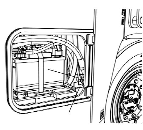
4. Remove the hose connected to the drain plug and remove the plug from the hose edge, then, open the cock.
5. Drain totally the oil. Fill the plug again with new oil and close the drain cock.
TAKE CARE OF THE ENVIRONMENT: All the used oil shall be properly stored for subsequent disposal. Do not dispose of oil on the ground, sewage system or other place which can harm the environment.
1. Clean the fuel tank
NEVER perform maintenance work under the machine when the engine is working. Always park the roller on a flat and safe place and chock the tires.
The fastest and simple way to clean the tank is when it is empty:
1. Open the filling cap (1) of fuel tank.
2. Place two proper containers under the drain plug of the fuel tank (2).
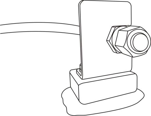
The drain plug of the fuel tank is on the right side of the machine, in a proper compartment.
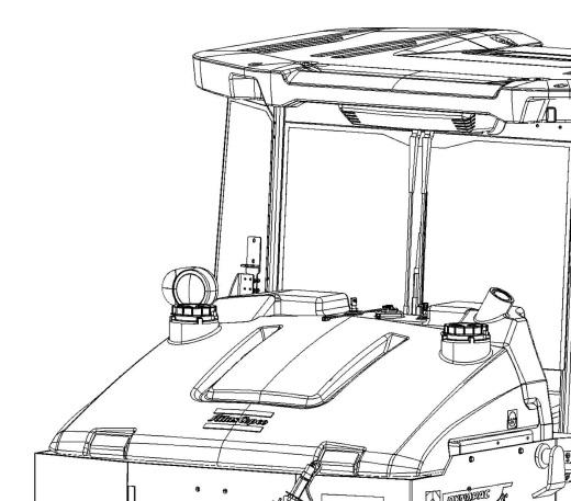
3. Unscrew the drain plug (2) and drain the remaining fuel inside the tank.
4. Refit the drain plug and tighten it.
Using adulterated, contaminated, dirty or bad quality fuel damages the injection system and engine components. The repairs due the conditions above are NOT covered by the warranty.
TAKE CARE OF THE ENVIRONMENT: All the used waste shall be properly stored for subsequent recycling. Do not dispose of any waste on the ground, sewage system or other place which can harm the environment.
Be extremely careful when handling fuel. There is risk of fire.
Clean the water tank
Wash the water tank adding a small quantity of a suitable detergent for plastic surfaces.
Close the drain cock (1), fill with water and check if there are leakages.
The water tank is made of plastic (polyethylene) and can be recycled.
Clean the sprinkler system
Keep in mind there are risks of freezing components during a cold weather. Empty the tanks, compartments, filters and tubes during such period or mixed fluid with water and antifreeze.
The coarse filter is inside the frame’s upper compartment, on the right side of the machine.
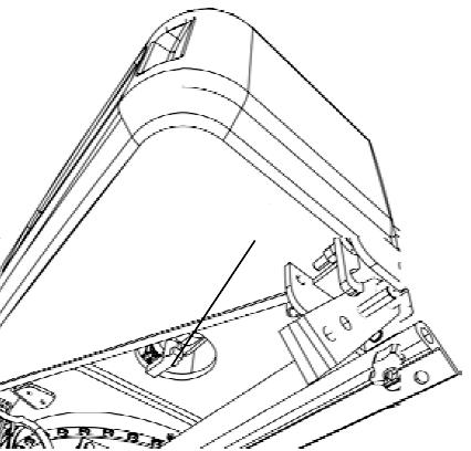
The filter housing (1) contains a drain cock (2) on the pumping system, in the water tank. The tank and pumping system parts can be drained through this cock.
The water hoses are connected to the pump with faster joints (3) to make the draining process easier. If necessary, replace the backup pump (if installed).
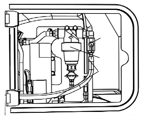
Replace the engine coolant
Caution! Risk of severe burns! Wait until the engine temperature cools down to 122 F (50°C) before removing the coolant tank cap or draining the coolant system.
1. Open the expansion tank cap.
NEVER open the coolant tank cap when the engine is hot.
2. Drain the engine coolant system through the cooler valve drain.
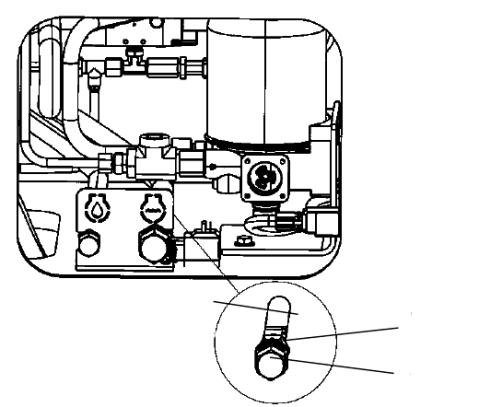
3. Use a proper container to collect the coolant (with 3.69 gal or 14 liters of capacity).
Be careful when draining the product. Use gloves and protective goggles.
TAKE CARE OF THE ENVIRONMENT: All used coolant shall be properly collected and store for subsequent recycling. Do not dispose of the coolant on the ground, sewage system or other place which can harm the environment.
4. Unscrew the hexagon nut (1), remove the hose (2) and unscrew the drain plug (4). Drain all the fluid to the container.
5. After the replacement, tighten the drain plug (4) and fit back the hose and the hexagon nut (1).
Check the air conditioning (if equipped)
Park the roller on a level surface.
When checking and adjusting the machine, always turn off the engine and make sure the forward/backward lever is in the "P" position.
Use compressed air to clean the dust off the condenser element (1). Clean from upwards to downwards.
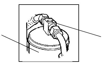
Do not use compressed air blows with too much power, otherwise the element fins can be damaged.
Always use protective goggles when working with compressed air.
Check if the condenser element is well secured.
Also check if the system hoses are not in contact with other components.
Check if there are no draining obstructions on the coolant unit. There is a risk of condensation being accumulated inside the unit.
Check the air conditioning draining filter (if equipped)
With the roller operating, use the sight glass (1) to check if there are bubbles on the drying filter.
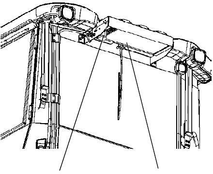
The filter is located on the upper rear of the cab's roof.
If there are visible bubbles, it means that the coolant level is too low. Turn off the machine to prevent damage and fill with coolant until it reaches the correct level.
Only authorized people/companies can carry out works on the coolant circuit.
Lubricate the upper/lower pivot bearing
1. Lubricate the grease fitting of the upper pivot bearing (1) and the grease fitting of the lower pivot bearing (2) operating the grease gun manually with five pump strokes.
2. Use the grease according to the lubricant specifications recommended by DYNAPAC.
Special instructions
Standard oil and fluid recommended
When the roller leaves the plant, its several systems are filled with oil or fluid indicated on the item "Symbols and Lubricants", which are proper for operating in places with temperatures between 5 F and 104 F (-15°C and 40°C).
The following recommendations are applied for operations in places with temperatures up to 104 F (40°C).
Highest temperature, from 122F (50°C).
The engine can work under this temperature using standard production oil, but for other components, use the following oils: Hydraulic system - mineral oil, Shell Tellus T100 or equivalent.
Lowest temperaturerisk of freezing
Temperatures
To prevent the system freezing, make sure that the system has been drained (sprinkler system, tank(s), hoses) or that antifreezing solutions were applied.
The limit temperatures are valid for series rollers.
The rollers with additional equipment, like noise level diminution equipment may need special attention when they are operated in high temperatures.
High pressure washing
It is important to keep in mind that the high pressure water must not be directed towards the fuel tank caps and the hydraulic system.
Cover the filling nozzle caps with plastic and lock them with rubber bands. It prevents the water to penetrate into the cap vent hole, which may cause damage on the involved systems and obstructions in the filters.
Never direct the high pressure water towards electric and electronic components or on the display (always keep them covered by covers or plastic).
Fire extinguisher If there is fire on the equipment, use a dry fire extinguisher or ABC class carbon dioxide. It is also possible to use a CO2 extinguisher (BE class).
Roll Over Protective Structure (ROPS)
NEVER weld or make holes on the ROPS.
NEVER repair a ROPS. Always replace it for a new one.
Battery handling
Special instructions
When removing the batteries, always turn off the negative cable first.
When mounting them, always turn on the positive cable first.
Dispose of the used batteries in an environmentally-friendly way. They do not contain toxic lead.
Never use fast charging in the battery. There is a risk of reducing its useful life.
Jump starting (24V)
Do not connect the negative cable to the negative pole in a dead battery. A spark may ignite a gas mixed combustion containing oxygen and hydrogen formed around the battery.
Check if the battery used for the jumper starting and the dead battery have the sam e tension.
Turn off the ignition key and all the power consuming equipment. Turn off the roller engine supplying power to the jump starting. The jump starting cables must have 24V.
Auxiliary starting
When using a booster battery besides the ones installed on the roller, always connect the positive post (+) of the booster battery to the positive post (+) of the installed battery, as well as the negative post (-) of the booster battery to the negative post (-) of the installed battery. Turn on the machine engine supplying power and let it work for a little while. Next, try to turn on the other machine. Then disconnect the cables in the reverse order.
Electrical system
Electrical system

The machine's main control box (1) is located on the rear of the operator platform. There is a plastic cap over it and the fuses.
A 24V jack is available in the plastic cap.
The fuses inside the engine compartment are located alongside the battery master switch.
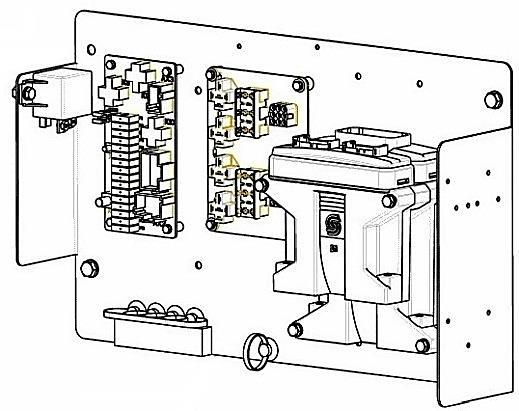
The roller is equipped with a 24V electrical system, supplied by an AC alternator.
Connect the batteries to the correct polarities (negative posts to the mass). NEVER disconnect the cable between the battery and the alternator when the engine is operating.
Electrical system
Fuses
F1 fuse box:
1. Ignition key, main relay (5A)
2. Main ECU, I/O unit, screen (5A)
3. Main ECU, PWR 1 (10A)
4. Main ECU, PWR 2 (10A) - option
5. Main ECU, PWR 3 (20A)
6. Main ECU, PWR 4 (20A)
7. Jack, 24V (10A)
8. Transmission ECU (10A)
F2 fuse box:
1. Air during the operation (5A) 2. Asphalt, (10A) 3.
Electrical system
Cab fuse box
1. Indoors lighting (10A)
2. Radio/CD player (10A)
3. Air conditioning (15A)
4. Heating (15A)
5. Windscreen wiper/washers, front/rear (10A)
6. Windscreen wiper/washers, right (10A)
7. Empty
8. Empty
The main fuses panel is behind the battery master switch, on the battery compartment.
1. General key
2. Pre-heating relay (120A)
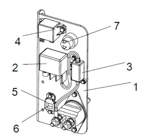
3. F20 fuse (pre-heating 120A)
4. Starting relay (50A)
5. F13 fuses (engine ECU: 30A), F10 (main: 50A) and F11 (cab: 50A)
6. F5 fuse (cab/Radio/CD player 10A)
7. 24V jack