11 minute read
Maintenance – List of fuels and lubricants

from Dynapac DRP45DX Reversible plate Operating & Maintenance Instruction Manual DL820355 - PDF DOWNLOAD

8.4 List of fuels and lubricants
Maintenance – Running-in instructions
8.5 Running-in instructions
8.5.1 General
The following maintenance work must be performed when running in new machines or overhauled engines.
8.5.2 After 25 operating hours
1. Change the engine oil.
2. Check the valve clearance, adjust if necessary ÄChapter 8.9.2 ‘Checking, adjusting the valve clearance’ on page 79
3. Check engine and machine for leaks.
4. Retighten the fastening screws on air filter, exhaust and other attachments.
5. Retighten the bolted connections on the machine.
6. Check the V-belt ÄChapter 8.11.3 ‘Servicing the V-belt’ on page 95
7. Check the oil level in the exciter shaft housing ÄChapter 8.11.4 ‘Checking the oil level in the exciter housing’ on page 96.
8.7 Weekly 8.7.1 Checking, cleaning the air filter
NOTICE!
Danger of engine damage!
–Do not start the engine after having removed the air filter.
–If necessary, the air filter may be cleaned up to six times.
–Cleaning does not make sense if the air filter element is covered with a sooty deposit.
–Do not use gasoline or hot fluids to clean the filter element.
–After cleaning, the air filter must be inspected for damage using a torch.
–Do not continue to use a damaged air filter element. If in doubt use a new air filter.
Protective equipment: n Working clothes n Safety shoes n Protective gloves n Safety goggles
1. Park the machine safely ÄChapter 6.4 ‘Parking the machine in secured condition’ on page 57
2. Allow the engine to cool down.
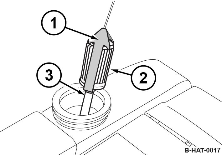
3. Remove the cap (3).
4. Unscrew the knurled nut (2) and pull out the air filter (1).
5. Clean the cover.
6.
NOTICE!
Danger of engine damage!
–Prevent dirt from getting into the air intake opening.
–Do not clean the air filter housing with compressed air.
Clean the filter housing with a clean, lint-free cloth.
7.
CAUTION!
Danger of eye injuries caused by particles flying around!
–Wear your personal protective equipment (safety gloves, protective working clothes, goggles).
Blow the air filter out with dry compressed air (max. 5 bar (73 psi)) from inside to outside by moving the gun up and down inside the element, until it is free of dust.
8. Examine the air filter with a torch for cracks and holes.
9. Replace the air filter if it is damaged.
10. Insert the air filter (1) carefully into the filter housing and fasten it with the knurled nut (2).
11.
NOTICE!
Danger of engine damage!
–Ensure correct fit of air filter cover and seal. Close the cap (3).
8.7.2 Checking and cleaning the water separator
The service intervals for the water separator depend on the water content in the fuel and can therefore not be determined precisely. After taking the engine into operation you should check for signs of water and dirt initially every day.
Protective equipment: n Working clothes n Safety shoes n Protective gloves
1. Park the machine safely ÄChapter 6.4 ‘Parking the machine in secured condition’ on page 57.
2. Place the transparent container under the drain plug.
3. Loosen the drain plug and collect escaping fluid.
4. Drain the fuel off until there is no water left.
5. Screw the drain plug back in tightly. Ensure leak tightness.
6. Dispose of collected fluid in line with environmental regulations.
8.8 Semi-annually
8.8.1 Battery service
Maintenance free batteries also need care. Maintenance free only means that the fluid level does not need to be checked.
Every battery has a self-discharge, which may, if not checked occasionally, even cause damage to the battery as a result of exhaustive discharge. Exhausted batteries (batteries with formation of sulphate on the plates) are not covered under warranty!
Protective equipment: n Working clothes n Safety shoes n Protective gloves n Safety goggles
1. Park the machine safely ÄChapter 6.4 ‘Parking the machine in secured condition’ on page 57
2. Remove the bracket (1) of the battery.
3. Remove the battery (3) and the vibration damping mats (2, 4, 5, 6).
4. Check the condition of the vibration insulation mats, replace if necessary.
5. Clean the outside of the battery.
6. Clean battery poles and pole clamps and grease them with pole grease (Vaseline).
7. On serviceable batteries check the acid level, if necessary top up to the filling mark with distilled water.
8. Install battery and vibration insulation mats.
9. Install the bracket of the battery.
Maintenance – Annually / every 250 operating hours
8.9 Annually / every 250 operating hours
8.9.1 Replacing the V-belt
Protective equipment: n Working clothes n Safety shoes n Protective gloves
1. Park the machine safely ÄChapter 6.4 ‘Parking the machine in secured condition’ on page 57 ð Nominal value: 384 ± 1 mm (15.1 ± 0.04 in)
2. Allow the engine to cool down.
3. Unscrew the V-belt guard (1).
4. Unscrew the guard (1).
5. Unscrew the V-belt pulley (1).
6. Replace the V-belt (3).
7. If necessary, reassemble the spacers (2) that may have been removed.
8. Fasten the V-belt pulley, tightening torque: 35 Nm (26 ft lbf).
9. Check the centre distance (x) between the centrifugal clutch (1) and the V-belt pulley (2).
If the centre distance is incorrect, contact our customer service.
10. Fasten the guard (1), tightening torque: 15 Nm (11 ft lbf).
8.9.1.1 Checking the frequency of the base plate
Keep feet and hands clear of the vibrating base plate.
CAUTION!
Danger of injury caused by uncontrolled machine movement!
–Always hold on to a running machine.
–Always keep an eye on a running machine.
Protective equipment: n Working clothes n Hearing protection n Safety shoes
Special tool: n Sirometer ð Nominal value: ÄChapter 2 ‘Technical data’ on page 11
1. Park the machine on a rubber mat.
2. Start the engine ÄChapter 6.2 ‘Starting the engine’ on page 53.
3. Run the machine at maximum speed for one minute.
4. Check the base plate’s frequency with a suitable measuring instrument (e.g. Sirometer).
5. Park the machine safely ÄChapter 6.4 ‘Parking the machine in secured condition’ on page 57
6. If frequency incorrect: n Check the engine speed. n Check the V-belt. n If necessary, contact our customer service.
8.9.2 Checking, adjusting the valve clearance
NOTICE!
Danger of engine damage! We recommend to have this work carried out by trained personnel or our after sales service.
–Before checking the valve clearance let the engine cool down.
Preparations
Protective equipment: n Working clothes n Protective gloves
1. Park the machine in secured condition ÄChapter 6.4 ‘Parking the machine in secured condition’ on page 57
2. Let the engine to cool down to ambient temperature.
Maintenance – Annually / every 250 operating hours
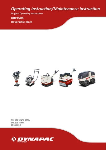
3. Remove the air filter cover (2).
4. Disassemble the covering (1).
5. Unscrew the fastening screws (1).
6. Remove the valve cover (2) with gasket.
Checking
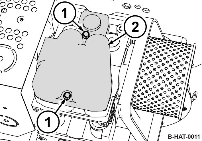
The Valve Clearance
Valve clearance:
Intake valve (IN) 0.20 mm (0.008 in)
Exhaust valve (EX) 0.20 mm (0.008 in)
1. Crank the engine, until the exhaust valve (EX) is fully open.
2. Check the valve clearance on the intake valve (IN) with a feeler gauge (1), adjust if necessary.
3. Crank the engine further, until the intake valve is fully open.
4. Check the valve clearance on the exhaust valve, adjust if necessary.
Adjusting the valve clearance
1. Loosen screw (3) on the rocker arm.
2. Adjust the hexagon nut (2), until the feeler gauge (1) can be inserted and pulled out with noticeable resistance after the screw (3) has been tightened.
1. Install the valve cover (2) with a new gasket.
2. Tighten the fastening screws (1) evenly.
3. Assemble covering (1) and air filter cover (2).
4. After a short test run check the valve cover for leaks.
8.9.3 Changing the engine oil and cleaning the oil filter
NOTICE!
Danger of engine damage!
–Change the oil only with the engine at operating temperature.
–Use only oil of the permitted specification
ÄChapter 8.3.1 ‘Engine oil’ on page 67
–Filling quantity: ÄChapter 8.4 ‘List of fuels and lubricants’ on page 70
Maintenance – Annually / every 250 operating hours
Protective equipment: n Working clothes n Protective gloves n Safety goggles
1. Park the machine in secured condition ÄChapter 6.4 ‘Parking the machine in secured condition’ on page 57
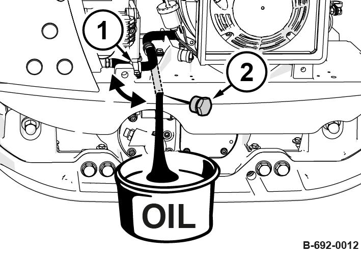
2. Clean the area around the dipstick and pull the dipstick out.
3. Clean the area around the drain hose.
4. Loosen the hose clamp (1) and route the drain hose to the outside.
5.
WARNING!
Danger of burning on hot components!
–Wear your personal protective equipment (protective gloves, protective clothing).
–Avoid touching hot components.
Unscrew the drain plug (2) and collect any oil running out.
6. Clean and screw in the drain plug.
7. Assemble the drain hose with the hose clamp.
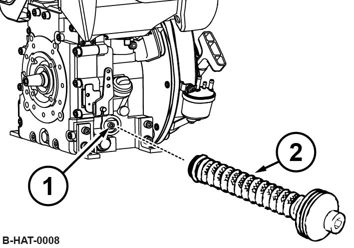
8. Loosen the screw (1) for approx. five turns and pull the oil filter (2) out of the housing.
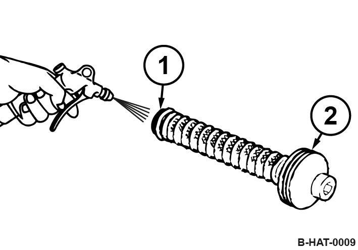
9.
CAUTION!
Danger of eye injuries caused by particles flying around!
–Wear your personal protective equipment (safety gloves, protective working clothes, goggles).
Use compressed air to blow the oil filter out from the inside to the outside.
10. Check the seal ring (2) for damage, change if necessary.
11. Slightly oil the seal rings (1) and (2).
Concluding work
8.9.4 Replacing the fuel filter
12. Insert the oil filter (2) into the housing and press it against the end stop.
13. Before tightening the screw (1) make sure that the tensioning springs touch the oil filter with both ends.
14. Tighten the screw.
15. Fill in fresh engine oil up to the bottom edge of the filling opening.
16. After a short test run check the oil level on the dipstick; if necessary, top up to the top dipstick mark.
17. Check oil filter and drain plug for leaks.
18. Dispose of oil in an environmentally friendly way.
NOTICE!
Danger of engine damage!
–Ensure strict cleanliness! Thoroughly clean the area around the fuel tank beforehand.
–Never operate the engine after having removed the fuel filter.
Protective equipment: n Working clothes n Protective gloves
1. Park the machine in secured condition ÄChapter 6.4 ‘Parking the machine in secured condition’ on page 57.
2. Clean the area around the tank filler cap.
3. Remove the tank filler cap.
4. Pull the fuel filter out of the tank by the string.
5. Pull the fuel hose (3) off the fuel filter (2).
6. Take the fuel filter out of the bracket (1) and replace it with a new one.
7. Plug on the fuel line.
8. Insert the fuel filter into the tank.
9. Close the fuel tank tightly.
The fuel system is self-bleeding.
10. Dispose of fuel and filter in an environmentally friendly way.
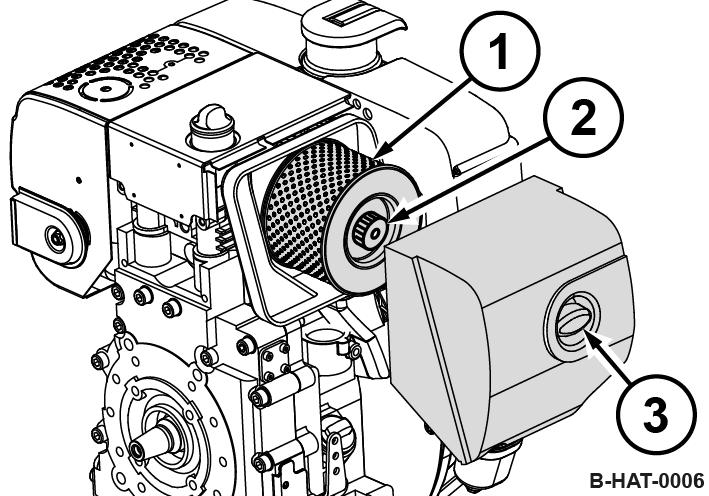
8.9.5 Replacing the air filter
NOTICE!
Danger of engine damage!
–Do not start the engine after having removed the air filter.
Protective equipment: n Working clothes n Protective gloves
1. Park the machine in secured condition ÄChapter 6.4 ‘Parking the machine in secured condition’ on page 57
2. Allow the engine to cool down.
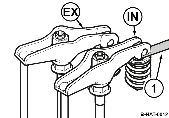
3. Remove the cap (3).
4. Unscrew the knurled nut (2) and pull out the air filter (1).
5. Clean the cover.
6.
NOTICE!
Danger of engine damage!
–Prevent dirt from getting into the air intake opening.
–Do not clean the air filter housing with compressed air.
Clean the filter housing with a clean, lint-free cloth.
7. Replace the air filter.
8. Insert the air filter (1) carefully into the filter housing and fasten it with the knurled nut (2).
9.
NOTICE!
Danger of engine damage!
–Ensure correct fit of air filter cover and seal.
Close the cap (3).
8.9.6 Changing the oil in the exciter housing
NOTICE! Components may get damaged!
–Use only oil of the permitted specification ÄChapter 8.4 ‘List of fuels and lubricants’ on page 70.
–Do not use low-ash engine oils for the exciter shaft housing.
Protective equipment: n Working clothes n Safety shoes n Protective gloves
1. Park the machine on level ground.
2. Park the machine safely ÄChapter 6.4 ‘Parking the machine in secured condition’ on page 57
3. Clean the area around the bleeding screw (1) and filling/drain plug (2).
4. Tilt the machine slightly towards the oil drain side and secure it properly.
5. Unscrew the bleeding screw.
6. Unscrew the filling/drain plug and collect any oil running out.
B-692-0013
7. Tilt the machine to the opposite side and secure it properly.
8. Fill in new oil.
9. Stand the machine horizontally and check the oil level. ð Nominal value: Bottom edge of filling/drain bore.
10. Clean the bleed screw (1) and filling/drain plug (2) and screw them in with a low-strength sealing agent (e.g. spare parts number: DL 009 700 16).
11. Dispose of oil in line with environmental regulations.
8.9.7 Checking the hydraulic oil level
Protective equipment: n Working clothes n Protective gloves
1. Park the machine in secured condition ÄChapter 6.4 ‘Parking the machine in secured condition’ on page 57
2. Adjust the steering rod with height adjustment so that the area with the filler screw is horizontal.
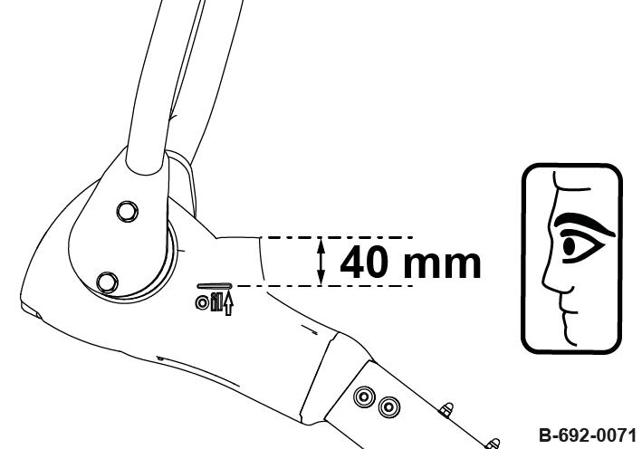
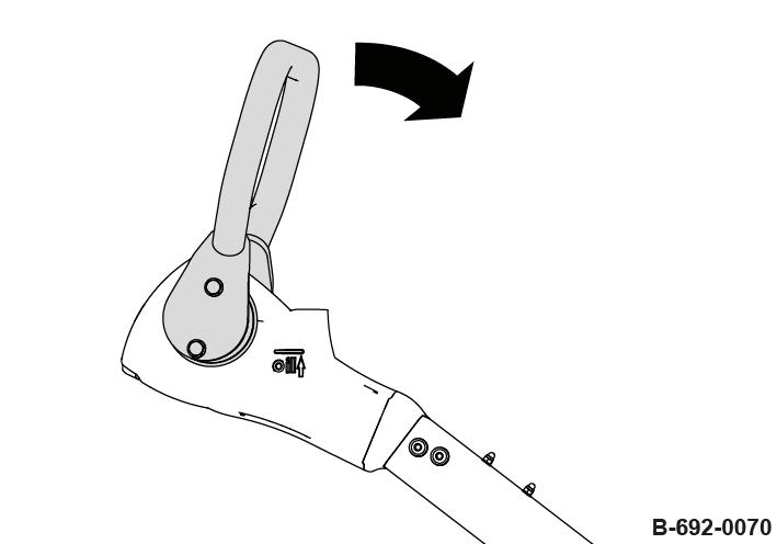
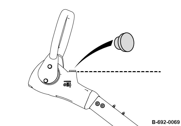
3. Unscrew the filler screw.
4. Press the handle forward against the stop and secure it using suitable means.
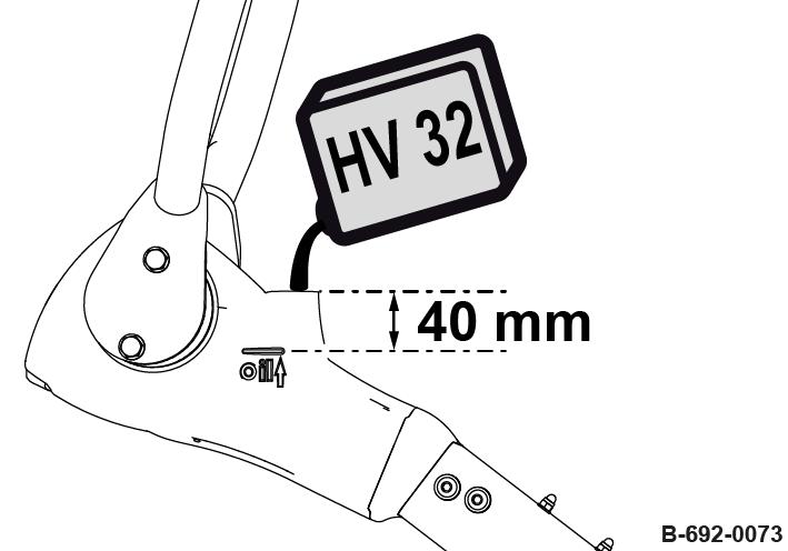
5. The oil level must reach the mark on the steering rod head, if necessary, fill in hydraulic oil.
Mark: approx. 40 mm (1.6 in) below the filler opening
NOTICE!
Components may get damaged! –Use only oil of the permitted specification.
6. Press the handle forward against the stop and secure it using suitable means.
7. Place a cloth underneath the bleeding screw to collect leaking oil.
8. Slacken the bleeding screw.
9. Wait until all air has escaped and then tighten the bleeding screw.
10. Fill in hydraulic oil up to the mark on the steering rod head.
11. Screw in the filler screw.
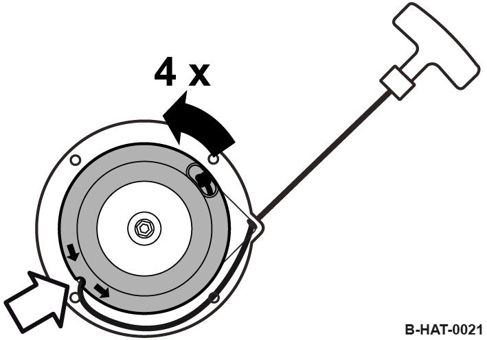
8.9.8 Replacing the starter rope
Protective equipment: n Working clothes n Protective gloves
1. Park the machine in secured condition ÄChapter 6.4 ‘Parking the machine in secured condition’ on page 57
2. Allow the engine to cool down.
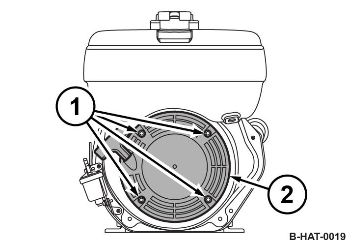
3. Unscrew the fastening screws (1) and disassemble the recoil starter (2).
4. Pull the starter rope with the starter handle (1) out completely.
5. Secure the coil (2) against winding up.
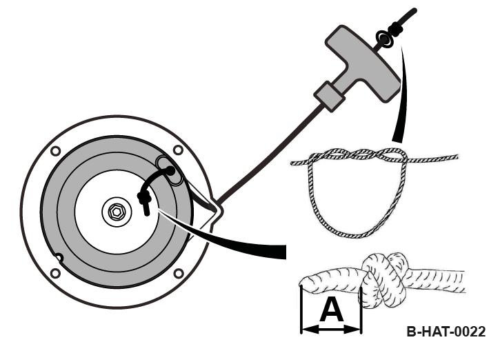
6. Loosen the knot (3) in the starter rope and remove the old starter rope.
7. Carefully turn the coil back, until the recoil spring is relieved.
8. Thread in the new starter rope and fix it with knots on both ends .
A = 15 mm (0.6 in)
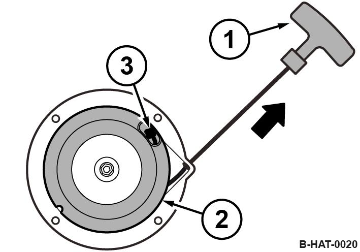
9. Pre-tension the coil by approx. 4 rotations in direction of arrow.
Thereby place the starter rope into the recess in the coil .
10.
CAUTION!
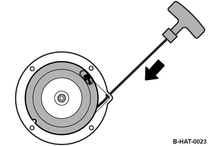
Danger of injury caused by the starter handle hitting against your body! –Do not let the starter handle hit back.
Slowly guide the starter handle back to initial position .
11. Pull the starter handle to check the function and light movement of the recoil starter.
12. Assemble the recoil starter (2) with fastening screws (1).
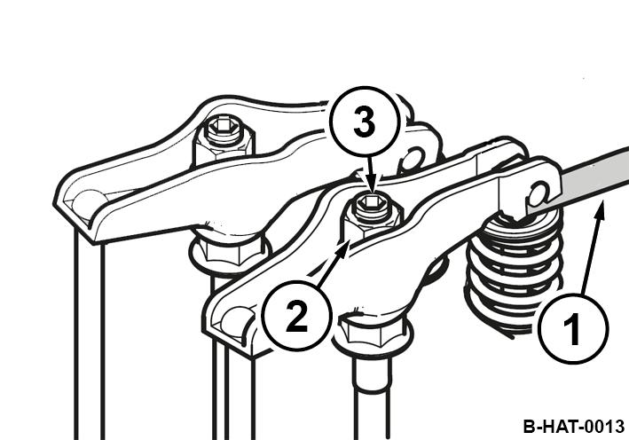
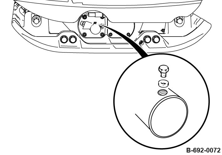
8.9.9 Lubricating the machine
Protective equipment: n Working clothes n Safety shoes n Protective gloves
1. Park the machine safely ÄChapter 6.4 ‘Parking the machine in secured condition’ on page 57
2. Unscrew the four fastening screws (1) and remove the cover (2).
3.
NOTICE!
Inadequate lubrication will cause damage to components!
–Use only grease of the permitted specification. (Spare parts number of lubrication grease: 924 109 63)
Grease the mechanical parts between the fork head (1), lever (2) and bolt (3).
4. Fasten the cover (2) with four fastening screws, tightening torque: 10 Nm (7.5 ft lbf).
Maintenance – Every 2 years / every 500 operating hours
8.10
Every 2 years / every 500 operating hours
8.10.1 Changing the hydraulic oil
Protective equipment: n Working clothes n Protective gloves
1. Park the machine in secured condition ÄChapter 6.4 ‘Parking the machine in secured condition’ on page 57
2. Adjust the steering rod with height adjustment so that the area with the filler screw is horizontal.
3. Unscrew the filler screw.
4. Press the handle forward against the stop and secure it using suitable means.
5. Unscrew the bleeding screw and collect any oil running out.
6. Screw in the bleeding screw.
7.
NOTICE!
Components may get damaged!
–Use only oil of the permitted specification.
Fill in hydraulic oil up to the mark on the steering rod head. Mark: approx. 40 mm (1.6 in) below the filler opening
8. Slacken the bleeding screw.
9. Wait until all air has escaped and then tighten the bleeding screw.
10. Fill in hydraulic oil up to the mark on the steering rod head.
11. Screw in the filler screw.
12. Dispose of oil in an environmentally friendly way.