18 minute read
Maintenance – Preliminary remarks and safety notes


8.1 Preliminary remarks and safety notes
DANGER!
Danger to life caused by an operationally unsafe machine!
–The machine must only be serviced by qualified and authorized personnel.
–Follow the safety regulations for maintenance work ÄChapter 3.9 ‘Maintenance work’ on page 32.
WARNING!
Health hazard caused by fuels and lubricants!
–Safety regulations and environmental protection regulations must be followed when handling fuels and lubricants ÄChapter 3.4 ‘Handling fuels and lubricants’ on page 23
Wear your personal protective equipment. Do not touch hot components.
Park the machine on horizontal, level, firm ground. Perform maintenance work only with the engine shut down and the spark plug connector disconnected.
Make sure that the engine cannot be accidentally started during maintenance work.
Thoroughly clean machine and engine before starting maintenance work.
Do not leave any tools or other objects, that could cause damage, in or on the machine.
After maintenance work has been completed, dispose of fuels and lubricants, filters, sealing elements and cleaning cloths in an environmentally friendly way.
After all maintenance work is completed reinstall all guards and safety installations.
8.2 Fuels and lubricants
8.2.1 Engine oil
8.2.1.1 Oil quality
Maintenance – Fuels and lubricants
The following engine oil specifications are permitted: n Engine oils for four-stroke engines acc. to API-classification SJ or higher
Avoid mixing of engine oils.
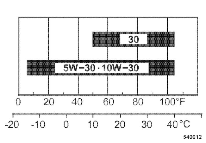
8.2.1.2 Oil viscosity
Since engine oil changes its viscosity with the temperature, the ambient temperature at the operating location of the engine is of utmost importance when choosing the viscosity class (SAE-class). The temperature data of the SAE-class always refers to fresh oils. In travel operation engine oil ages because of soot and fuel residues. This adversely affects the properties of the engine oil, especially under low ambient temperatures.
SAE 10W-30 is recommended for general use.
You may alternatively use 15W-40 (except under low temperatures).
8.2.1.3 Oil change intervals
8.2.2 Fuel
8.2.2.1 Fuel quality
Oil change interval: semi-annually or every 100 operating hours.
Use unleaded gasoline with a research octane number of 91 or higher (or octane number 86 or higher).
Use unleaded standard grade gasoline with maximum 10 percent by volume of ethanol (E10) or maximum 5 percent by volume of methanol.
Methanol must also contain co-solvents and corrosion inhibitors. Do not use any fuel with a higher ethanol or methanol content. The use of fuels with a higher ethanol or methanol content will cause starting and/or power problems or even cause damage in the fuel system.
8.2.2.2 Fuel stabilizer
If the machine is only occasionally used (if it is out of use for longer than four weeks), mix in the correct amount of fuel stabilizer directly after you have purchased fresh fuel.
The fuel stabilizer has a limited shelf life.
Please follow the instructions of the manufacturer concerning the correct mixing ratio and shelf life.
Mixing in fuel stabilizer does not regenerate old fuel.
8.2.3 Oil for exciter shaft housing
Use only engine oils according to the following specifications: n API CI-4 or higher quality
Avoid mixing engine oils.
NOTICE!
Components may get damaged! –Do not use low-ash engine oils for the exciter shaft housing.
8.3 List of fuels and lubricants
Maintenance – List of fuels and lubricants
Maintenance – Running-in instructions
8.4 Running-in instructions
8.4.1 General
The following maintenance work must be performed when running in new machines or overhauled engines.
8.4.2 After 25 operating hours
1. Change the engine oil ÄChapter 8.7.1 ‘Changing the engine oil’ on page 79
2. Check engine and machine for leaks.
3. Retighten the fastening screws on air filter, exhaust and other attachments.
4. Retighten the bolted connections on the machine.
5. Checking the V-belt ÄChapter 8.9.4 ‘Servicing the V-belt’ on page 94
6. Check the oil level in the vibrator housing.
8.6 Weekly 8.6.1 Checking, cleaning the air filter
NOTICE!
Danger of engine damage!
–Do not start the engine after having removed the air filter.
–If necessary, the air filter may be cleaned up to six times.
–Cleaning does not make sense if the air filter element is covered with a sooty deposit.
–Do not use gasoline or hot fluids to clean the filter element.
–After cleaning, the air filter must be inspected for damage using a torch.
–Do not continue to use a damaged air filter element. If in doubt use a new air filter.
Protective equipment: n Working clothes n Safety shoes n Protective gloves n Safety goggles
1. Park the machine safely ÄChapter 6.5 ‘Parking the machine in secured condition’ on page 62
2. Allow the engine to cool down.
3. Unscrew wing nut (1) and remove cover (2).
4. Clean the cover.
5. Unscrew wing nut (3) and remove filter element (4).
6. Check the rubber seal (5), replace if necessary.
The rubber seal frequently sticks to the filter element.
Checking, cleaning the air filter
7. Separate paper element and foam element.
8.
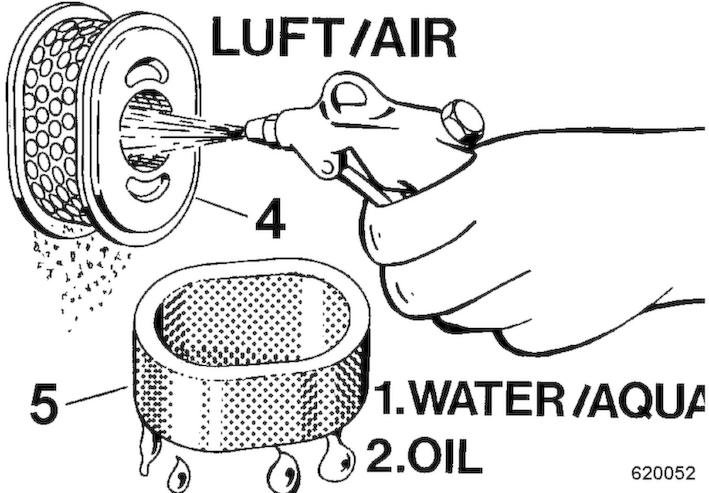
CAUTION!
Danger of eye injuries caused by particles flying around!
–Wear your personal protective equipment (safety gloves, protective working clothes, goggles).
Blow the paper element (4) out with dry compressed air (max. 2 bar (29 psi)) from inside to outside by moving the gun up and down inside the element, until it is free of dust.
9. In case of excessive dirt, replace the paper element.
10. Clean the foam element (5) in warm soapy water, rinse it and let it dry thoroughly.
11. Soak the foam element in clean engine oil and press excessive oil out.
12. Check both elements thoroughly for holes and cracks.
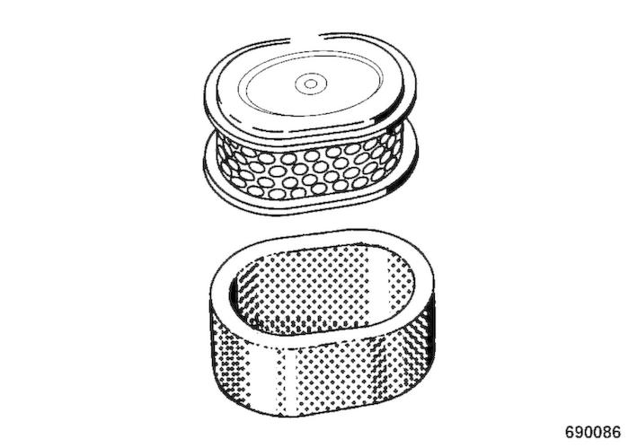
13. Replace if damaged.
14. Pull the foam rubber element over the paper element.
Assembling the air filter
NOTICE! Danger of engine damage! –Insert the filter element correctly.
15. Install the rubber seal (5).
16. Insert the filter element (4) correctly and tighten it with the wing nut (3).
17. Tighten the cover (2) with the wing nut (1).
18. Dispose of the filter element (if replaced) in an environmentally friendly way.
8.7 Semi-annually
8.7.1 Changing the engine oil
B-SYM-1078
NOTICE!
Danger of engine damage!
–Change the oil only with the engine at operating temperature.
–Use only oil of the permitted specification
ÄChapter 8.2.1 ‘Engine oil’ on page 71
–Filling quantity: ÄChapter 8.3 ‘List of fuels and lubricants’ on page 73
Protective equipment: n Working clothes n Safety shoes n Protective gloves
1. Park the machine safely ÄChapter 6.5 ‘Parking the machine in secured condition’ on page 62
2.
WARNING!
Danger of burning on hot components! –Wear your personal protective equipment (protective gloves, protective clothing). –Avoid touching hot components.
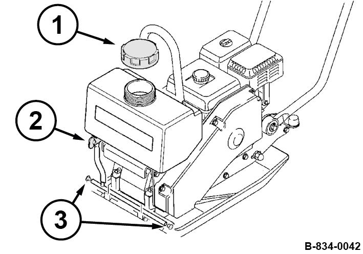
Clean the area around oil dipstick (1) and drain plug (3).
3. Unscrew the oil dipstick.
4. Unscrew the drain plug and collect any oil running out.
5. Clean the oil drain plug and screw it back in with a new seal ring (2).
6. Fill in fresh oil up to the bottom edge of the filler bore.
7. Push the oil dipstick (1) back in.
8. Check for leaks after a short test run.
9. Check the oil level on the dipstick, correct if necessary.
10. Dispose of oil in line with environmental regulations.
8.8 Annually
8.8.1 Replacing the spark plug
NOTICE!
Danger of engine damage!
–Do not use spark plugs with incorrect heat value.
Recommended spark plugs:
NGK
DENSO
BPR6ES
W20EPR-U
Protective equipment: n Working clothes n Protective gloves
Special tool: n 13/16 inch spark plug spanner
1. Park the machine in secured condition ÄChapter 6.5 ‘Parking the machine in secured condition’ on page 62 ð Nominal value: 0.7 - 0.8 mm (0.028 - 0.032 in)
2. Allow the engine to cool down for at least 15 minutes.
3. Clean the area around the spark plug.
4. Unscrew the spark plug using a 13/16 inch spark plug spanner.
5. Check the electrode gap of the new spark plug with a feeler gauge, if necessary, adjust the gap.

6. Screw in the new spark plug carefully by hand.
7. Once the sealing surface of the new spark plug is in contact, tighten for another 1/2 turn with the spark plug spanner.
8.8.2 Checking, adjusting the valve clearance
NOTICE!
Danger of engine damage! We recommend to have this work carried out by trained personnel or our after sales service.
–Before checking the valve clearance let the engine cool down.
Preparations
Protective equipment: n Working clothes n Protective gloves
1. Park the machine in secured condition ÄChapter 6.5 ‘Parking the machine in secured condition’ on page 62
2. Let the engine cool down to 20 °C (68 °F).
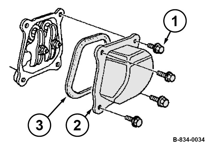
3. Unscrew the fastening screws (1).
4. Remove valve cover (2) with seal (3).
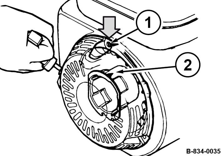
5. Set the piston to the top dead centre position of the compression stroke.
For this purpose align the alignment mark (2) on the starter disc to the top bore (1).
1. Check the valve clearance with a feeler gauge between rocker arm (2) and valve shaft (1) on both valves, adjust if necessary.
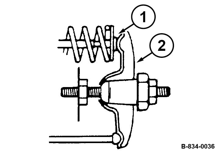
Adjusting the valve clearance
1. Hold the hexagon nut (1) on the rocker arm and loosen counter nut (2).
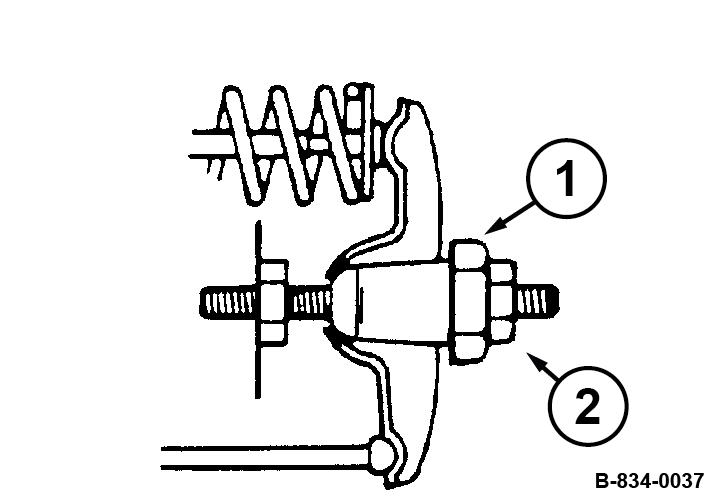
2. Adjust the hexagon nut, until the feeler gauge can be inserted and pulled out with little resistance after retightening the counter nut.
Concluding work
1. Install the valve cover (2) with a new seal (3).
2. Tighten the fastening screws (1) evenly.
3. After a short test run, check the engine for leaks.
8.8.3 Replacing the V-belt
Protective equipment: n Working clothes n Safety shoes n Protective gloves
1. Park the machine safely ÄChapter 6.5 ‘Parking the machine in secured condition’ on page 62.
2. Allow the engine to cool down.
3. Loosen the fastening screws (2) and remove the V-belt guard (1).
4. Slightly loosen the fastening screws (2) on both sides.
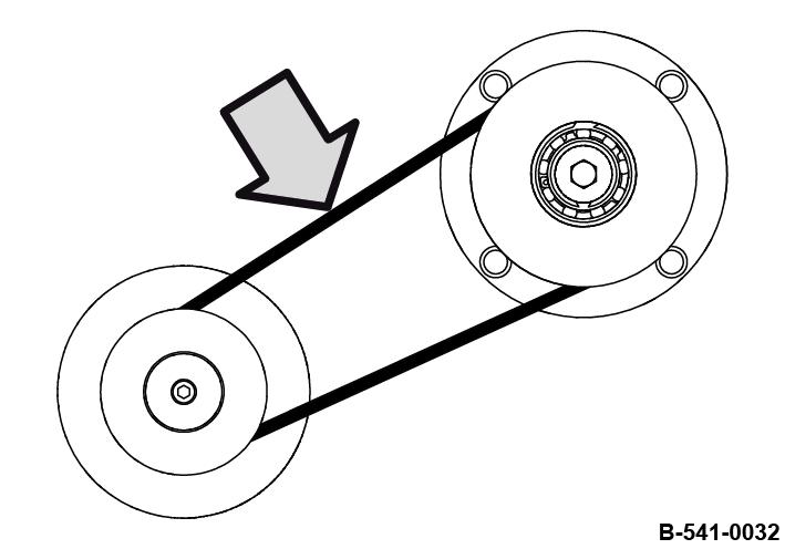
5. Pull the engine carrier forward, remove and replace the Vbelt (1).
B-834-0170
6. Install the new V-belt and pull the engine carrier back.
7. Tighten the fastening screws (1) on both sides.
B-834-0171
8. Check tension of V-belt, tighten if necessary. ð Compression measurement: approx. 5 mm (0.2 in).
9. Assemble the V-belt guard (1) with fastening screws (2).
10. Check the V-belt tension again after 25 operating hours, tighten if necessary.
8.8.3.1 Checking the frequency of the base plate
Keep feet and hands clear of the vibrating base plate.
CAUTION!
Danger of injury caused by uncontrolled machine movement!
–Always hold on to a running machine.
–Always keep an eye on a running machine.
Protective equipment: n Working clothes n Hearing protection n Safety shoes
Special tool: n Sirometer
1. Park the machine on a rubber mat.
2. Start the engine ÄChapter 6.2 ‘Starting the engine’ on page 55 ð Nominal value: ÄChapter 2 ‘Technical data’ on page 11
3. Run the machine at maximum speed for one minute.
4. Check the base plate’s frequency with a suitable measuring instrument (e.g. Sirometer).
5. Park the machine safely ÄChapter 6.5 ‘Parking the machine in secured condition’ on page 62.
6. If frequency incorrect: n Check the engine speed. n Check the V-belt. n If necessary, contact our customer service.
8.8.4 Cleaning the slurry filter and fuel strainer
DANGER!
Danger to life caused by explosive gas-air mixes!
–Do not allow gasoline to come into contact with hot components.
–Smoking and open fire is prohibited.
–Keep away from heat sources, sparks and other sources of ignition.
–Do not spill any gasoline.
Protective equipment: n Working clothes n Safety shoes n Protective gloves
1. Park the machine safely ÄChapter 6.5 ‘Parking the machine in secured condition’ on page 62
2. Allow the engine to cool down.
3. Close the fuel valve.
4. Disassemble filter bowl (3), O-ring (2) and filter (1).
5. Clean filter bowl and filter in a non-inflammable solvent, dry them thoroughly afterwards.
6. Open the fuel valve and collect running out fuel.
7. Close the fuel valve.
8. Check the O-ring (2) for damage, replace if necessary.
9. Install the filter (1).
Observe the alignment (A) of the filter on the housing.
10. Assemble the filter bowl (3) with the O-ring.
11. Unscrew the hexagon nuts (2) and the hexagon screw (1) and take off the fuel tank.
12. Loosen the hose clamp (1) and pull off the fuel hose.
13. Unscrew the fuel strainer (3) with the seal (2).
14. Clean the fuel strainer, check the condition of the screen, replace if necessary.

15. Turn the fuel strainer tightly in with the new seal.
16. Assemble the fuel hose with the hose clamp.
8.8.5 Replacing the air filter
17. Assemble the fuel tank with hexagon nuts (2) and hexagon screw (1).

18. Check the fuel system for leaks.
19. Dispose of fuel and replaced components in an environmentally friendly way.
NOTICE!
Danger of engine damage!
–Do not start the engine after having removed the air filter.
Protective equipment: n Working clothes n Safety shoes n Protective gloves
1. Park the machine safely ÄChapter 6.5 ‘Parking the machine in secured condition’ on page 62
2. Allow the engine to cool down.
3. Unscrew wing nut (1) and remove cover (2).
4. Clean the cover.
5. Unscrew wing nut (3) and remove filter element (4).
6. Check the rubber seal (5), replace if necessary.
The rubber seal frequently sticks to the filter element.
8.8.6 Replacing the starter rope
7. Replace the filter element consisting of paper and foam insert.
NOTICE!
Danger of engine damage! –Insert the filter element correctly.
8. Install the rubber seal (5).
9. Insert the filter element (4) correctly and tighten it with the wing nut (3).

10. Tighten the cover (2) with the wing nut (1).
11. Dispose of the old filter element in an environmentally friendly way.
Protective equipment: n Working clothes n Protective gloves
1. Park the machine in secured condition ÄChapter 6.5 ‘Parking the machine in secured condition’ on page 62
2. Allow the engine to cool down.
3. Disassembling the recoil starter.
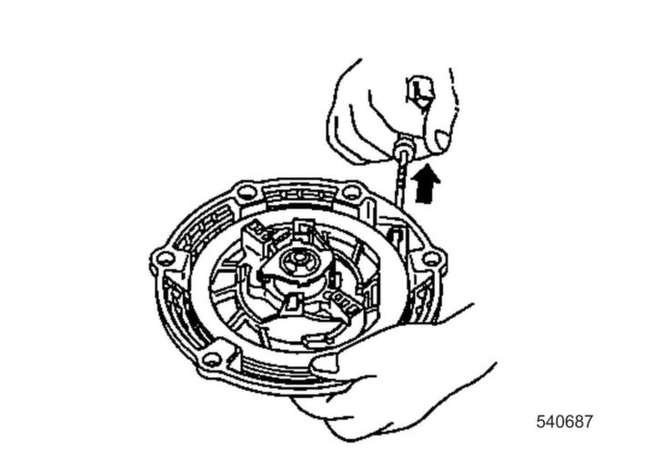
4. Pull the starter rope with the starter handle out completely.
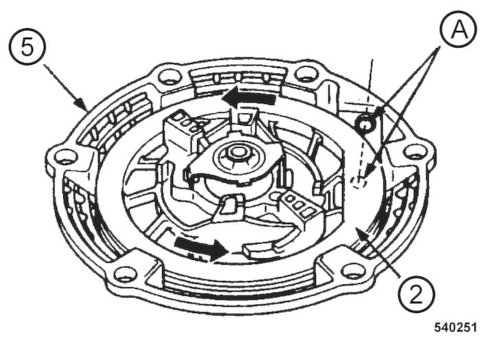
5. If the starter rope has been torn or the coil has recoiled completely: n Before assembling the rope, turn the coil (2) 5 revolutions in anti-clockwise direction and align the rope openings in coil and housing (5) to one another (A).
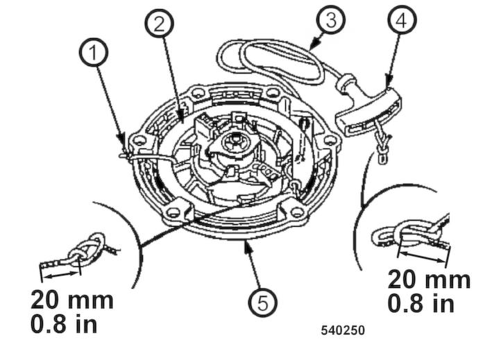
6. Secure the coil against winding up. For this purpose tie the coil (2) to the housing (5) with a cable strap (1).
7. Untie the knots of the starter rope at both ends and remove the old starter rope.
8. Thread in the new starter rope (3) and fix it with knots on both ends.
9.
CAUTION!
Danger of injury caused by the starter handle hitting against your body!
–Do not let the starter handle hit back.
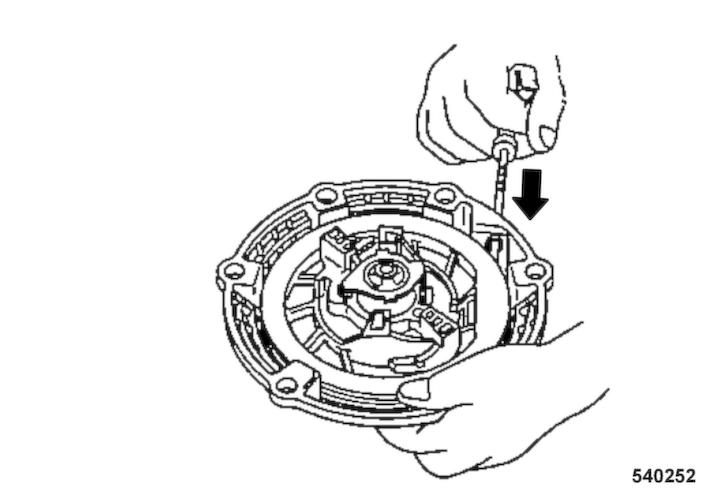
Remove the fixing of the coil and run the starter handle slowly back to initial position.
10. Pull the starter handle to check the function and light movement of the recoil starter.
11. Assemble the recoil starter.
8.8.7 Changing the oil in the exciter housing
NOTICE!
Components may get damaged!
–Use only oil of the permitted specification ÄChapter 8.3 ‘List of fuels and lubricants’ on page 73
Protective equipment: n Working clothes n Safety shoes n Protective gloves
1. Drive the machine onto horizontal, level, firm ground.
2. Park the machine safely ÄChapter 6.5 ‘Parking the machine in secured condition’ on page 62.
3. Tilt the machine slightly towards the oil drain side and secure it properly.
4. Clean the area around the filler plug (1) and the drain plug (2).
5. Unscrew the filler plug and drain plug.
6. Collect leaking oil.
B-834-0302
7. Tilt the machine to the opposite side and secure it properly.
8. Screw the drain plug back in.
NOTICE!
Components may get damaged! Do not use low-ash engine oils for the exciter shaft housing.
Observe the filling quantity ÄChapter 8.3 ‘List of fuels and lubricants’ on page 73
9. Fill in oil.
10. Stand the machine horizontally and check the oil level. ð The oil level must reach the bottom edge of the filler opening.
11. Screw the filler plug back in.
12. Dispose of oil in line with environmental regulations.
8.9 As required
8.9.1 Cleaning the cooling fins and the cooling air intake openings
How dirty the cooling fins and cooling air intake openings are depends very much on the daily operating conditions; clean daily if necessary.
NOTICE!
Danger of engine damage caused by reduced cooling!
–For this reason you should always seal any oil or fuel leaks in the vicinity of the cooling fan or the coolers and clean the cooling fins after.
Protective equipment: n Working clothes n Protective gloves n Safety goggles
1. Park the machine in secured condition ÄChapter 6.5 ‘Parking the machine in secured condition’ on page 62
2. Allow the engine to cool down.
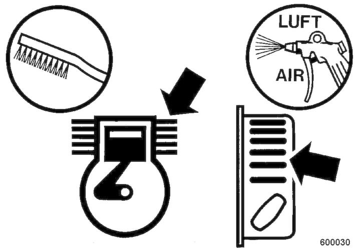
3. Remove dried dirt with a suitable brush from all cooling fins and cooling air intake openings.
4.
CAUTION!
Danger of eye injuries caused by particles flying around!
–Wear your personal protective equipment (safety gloves, protective working clothes, goggles).
Blow out the cooling fins and cooling air intake openings with compressed air.
Cleaning with cold cleansing agent
If the engine is oily, use a cold cleansing agent for cleaning.
NOTICE!
Components can be damaged by water entering into the system!
–Do not direct the water jet directly into the air filter, carburettor, recoil starter, air intake or starter switch.
1. CAUTION!
Danger of eye injuries caused by particles flying around!
–Wear your personal protective equipment (safety gloves, protective working clothes, goggles).
Spray the engine with a suitable, non-inflammable cleansing agent, let is soak in for a while, clean it off with water and blow out with compressed air.
2. Warm up the engine for a while to avoid corrosion.
3. Look for the cause of oily contamination and have any leaks sealed by our customer service.
8.9.2 Cleaning the machine
NOTICE!
Danger of engine damage caused by reduced cooling!
–Immediately seal any oil or fuel leaks near fuel tank, cylinder or cooling air intake.
1. Park the machine in secured condition ÄChapter 6.5 ‘Parking the machine in secured condition’ on page 62
2. Allow the engine to cool down for at least 30 minutes.
NOTICE!
Components can be damaged by water entering into the system!
–Do not direct the water jet directly into the air filter, carburettor, recoil starter, air intake or starter switch.
3. Clean the machine with a water jet.
4. Run the engine warm for a while to avoid corrosion.
Maintenance – As required
8.9.3 Cleaning the water spraying system
1. Park the machine in secured condition ÄChapter 6.5 ‘Parking the machine in secured condition’ on page 62
2. Remove the cap (1) from the water tank.
3. Remove the rubber caps (3) from the spray tube.
4. Open shut-off valve (2) and drain off all water.
5. Flush the water tank with a strong water jet, until all dirt has run out.
6. Plug the rubber caps back on the spray tube.
7. Fill the water tank with clean water and close the cap.
8.9.4 Servicing the V-belt
Protective equipment: n Working clothes n Safety shoes n Protective gloves
1. Park the machine safely ÄChapter 6.5 ‘Parking the machine in secured condition’ on page 62 ð Compression measurement: approx. 5 mm (0.2 in).
2. Allow the engine to cool down.
3. Loosen the fastening screws (2) and remove the V-belt guard (1).
4. Check condition and tension of the V-belt, tighten if necessary.
5. If necessary, tighten the V-belt; if damaged, replace the Vbelt ÄChapter 8.8.3 ‘Replacing the V-belt’ on page 82
6. Assemble the V-belt guard (1) with fastening screws (2).
8.9.5 Checking, cleaning the spark plug
NOTICE!
Danger of engine damage!
–Do not use spark plugs with incorrect heat value.
Protective equipment: n Working clothes n Protective gloves
Special tool: n 13/16 inch spark plug spanner
1. Park the machine in secured condition ÄChapter 6.5 ‘Parking the machine in secured condition’ on page 62
2. Allow the engine to cool down for at least 15 minutes.
3. Clean the area around the spark plug.
4. Unscrew the spark plug using a 13/16 inch spark plug spanner.
5. Check the condition of the spark plug, clean if necessary.
6. In case of excessive combustion residues or burned off electrodes, replace the spark plug ÄChapter 8.8.1 ‘Replacing the spark plug’ on page 80 ð Nominal value: 0.7 - 0.8 mm (0.028 - 0.032 in)

7. Check the electrode gap of the spark plug with a feeler gauge, if necessary, adjust the gap.
8. Carefully screw in the spark plug by hand.
9. Once the sealing surface of the used spark plug is in contact, tighten for another 1/8 to 1/4 turn with the spark plug spanner.
NOTICE!
Danger of engine damage caused by a loose spark plug!
–Always screw the spark plug in correctly.
8.9.6 Measures if there is a risk of frost
1. Park the machine safely ÄChapter 6.5 ‘Parking the machine in secured condition’ on page 62.
2. Remove the cap (1) from the water tank.
3. Remove the rubber caps (3) from the spray tube.
4. Open shut-off valve (2) and drain off all water.
5. Insert the rubber caps.
6. Close the shut-off valve.
7. Close the cap.
8.9.7 Measures prior to extended shut-down period
8.9.7.1 Measures before shutting down
DANGER!
Danger to life caused by explosive gas-air mixes!
–Do not allow gasoline to come into contact with hot components.
–Smoking and open fire is prohibited.
–Keep away from heat sources, sparks and other sources of ignition.
–Do not spill any gasoline.
If the machine is shut down for a longer period of time, e.g. winter season, the following work must be carried out. Depending on weather influences these conservation measures will protect the machine for approx. 6 to 12 months.
1. Park the machine safely ÄChapter 6.5 ‘Parking the machine in secured condition’ on page 62
2. Allow the engine to cool down for at least 30 minutes.
3. Clean the machine thoroughly.
4. Change the engine oil ÄChapter 8.7.1 ‘Changing the engine oil’ on page 79
5. Use fuel stabilizer or empty the fuel tank completely.
Using fuel stabilizer
1. Mix fresh fuel with fuel stabilizer (follow the instructions of the manufacturer).
2. Empty the fuel tank and fill it with the prepared fuel mix.
3. Start the engine and run the machine for approx. 10 minutes in the open.
4. Park the machine in secured condition.
2. Disassemble the drain plug (3) and the seal (4) from the carburettor and collect leaking fuel.
3. Disassemble the filter bowl (2) and the O-ring (1).
4. Open the fuel valve and collect running out fuel.
5. Close the fuel valve.
6. Install the drain plug with the seal on the carburettor.
7. Assemble the filter bowl with the O-ring.
8. Dispose of fuel in line with environmental regulations.
Special tool: n 13/16 inch spark plug spanner ð Valves are closed so that no moisture can enter into the cylinder.
1. Unscrew the spark plug using a 13/16 inch spark plug spanner.
2. Fill in several drops of fresh engine oil through the ignition plug opening.
3. Crank the engine several times with the recoil starter to distribute the oil in the cylinder.
4. Screw the spark plug back in.
5. Slowly pull the starter rope until resistance can be felt and the alignment mark (2) on the starter disc is in line with the upper bore (1).
6. Slowly guide the starter rope back.
1. After shutting down store the machine under cover in a dry and well ventilated room.
2. Repair damaged paint; preserve bare areas thoroughly with anti-corrosive agent.
3. Cover the engine to protect it against dust and moisture.
4. A machine with conserved engine must be clearly marked by attaching an information sign.
8.9.7.2 Measures before restarting
DANGER!
Danger to life caused by explosive gas-air mixes!
–Do not allow gasoline to come into contact with hot components.
–Smoking and open fire is prohibited.
–Keep away from heat sources, sparks and other sources of ignition.
–Do not spill any gasoline.
1. Check the oil levels.
2. If the fuel was drained off before shutting down, you must now fill in fuel.
3. Check hoses and lines for cracks and leaks.
4. Clean the machine thoroughly.
5. Start the engine and run it for 15 to 30 minutes with idle speed.
9.1 Preliminary remarks
Malfunctions are frequently caused by incorrect operation of the machine or insufficient maintenance. Whenever a fault occurs you should therefore thoroughly read these instructions on correct operation and maintenance.
If you cannot locate the cause of a fault or rectify it yourself by following the trouble shooting chart, you should contact our customer service department.
9.2 Engine malfunctions
Malfunction Possible cause
Engine does not start
Fuel tank empty
Fuel valve closed
Fuel system clogged
Troubleshooting – Engine malfunctions
Remedy
Check, fill up if necessary
Open the fuel valve
Clean the fuel screen
Check the fuel screen in the carburettor
Have checked by qualified expert personnel
Set the starter switch to “OFF” position
Engine oil level too low
No ignition spark
Starter switch defective
No fuel in carburettor
Set the starter switch to “ON” position
Check the engine oil level, correct if necessary
Clean the spark plug, replace if necessary
Have checked by qualified expert personnel
Check the fuel supply
Have checked by qualified expert personnel
Engine does not crank when operating the recoil starter
Starter rope of recoil starter does not return to initial position
Recoil starter defective
Spring broken
Recoil starter dirty
Insufficient pre-tension of the spring
Spring broken
Low engine power Air filter clogged
Throttle cable defective
Engine defective
Carburettor defective
Engine overheats Lack of cooling air
Engine stops Fuel system clogged
Fuel tank empty
Replace the recoil starter
Replace the recoil starter
Clean the recoil starter
Check the pre-tension of the spring, adjust if necessary
Replace the recoil starter
Clean the air filter, replace if necessary
Have checked by qualified expert personnel
Have checked by qualified expert personnel
Have checked by qualified expert personnel
Clean the air filter, replace if necessary
Cleaning the cooling fins and the cooling air intake openings
Clean the fuel screen
Check the fuel screen in the carburettor
Have checked by qualified expert personnel
Check, fill up if necessary