17 minute read
KEEPTHIS MANUALAVAILABLEFORFUTUREUSE

The CC102/122 are specially designed for repair work on asphalt compounds, but can also be used for paving small streets, sidewalks and bicycle trails. They are often used as a complement to bigger rollers for compacting cross-joints and restricted spaces.
The CC122C is a light combo roller that are used for compacting thin layers and soft asphalt compounds.
The CC142 is a typical ”town roller” for compacting asphalt compounds on streets, parking lots and industrial sites. The capacity for this type of work is adequate for following a smaller-size surface finisher.
The CC142C is also intended for minor paving jobs on low-traffic asphalt areas where a level and attractive surface structure is desired. Typical workplaces—in addition to sidewalks and bicycle trails—are therefore parks, golf courses and sports fields.
Contents
Warning Symbols
Safety instructions—Personal safety.
Special caution—Machine or component damage.
Safety Manual
Each operator of the roller must study the safety manual that accompanies each machine. Always follow the safety rules and do not remove the manual from the roller.
General
This manual contains instructions for operation and use of the roller. For care and maintenance information, see the MAINTENANCE, CC102/122/C/142/C manual.
Remember that when you start and drive a cold machine, the hydraulic fluid is cold and the braking distance will be longer than normal until the machine reaches normal working temperature.
California
Proposition 65 Warning
Diesel engine exhaust and some of its constituents are known to the State of California to cause cancer, birth defects, and other reproductive harm.
SAFETY INSTRUCTIONS (Also read the safety manual)
1. The operator must be familiar with the contents of the OPERATION MANUAL before starting the roller.
2. Make sure that all instructions in the MAINTENANCE MANUAL are followed.
3. Only trained and/or experienced operators are allowed to drive the roller. Passengers are not allowed on the roller. Remain seated during all operation.
4. Never use the roller if it is in need of adjustment or repairs.
5. Board and leave the roller only when it is stationary. Use the grips and railings that are provided. A ”three-point grip” is recommended whenever you board or leave the machine—both feet and one hand, or one foot and both hands in contact with the machine.
6. Always use the Roll Over Protective Structure (ROPS) when the machine is used on risky ground.
7. Drive slowly in sharp bends.
8. Avoid driving at an angle on slopes; drive straight up or down.
9. When driving close to unsafe edges or holes, make sure that at least two thirds of the drum width is firmly on material that has already been compacted.
10. Make sure that there are no obstacles in the direction of travel, on the ground or overhead.
11. Drive extra carefully on uneven ground.
12. Use the safety equipment provided. The seat belt must be worn on machines fitted with ROPS.
13. Keep the roller clean. Clean dirt and grease from the operator’s platform without delay. Keep all signs and decals clean and clearly legible.
14. Safety measures before refueling:
– Stop the engine.
– Don’t smoke.
– No naked flame in the vicinity.
– Ground the nozzle of the filling device against the tank to prevent sparks.
15. Before repairs or service:
– Place chocks against the drums/wheels and against the strike-off blade.
– Lock the articulation if necessary.
16. Hearing protectors are recommended if the noise level is higher than 85 db(A). The noise level will vary depending on the surface being worked on by the machine.
17. Make no changes or modifications on the roller that could affect safety. Changes may only be made following written consent by Dynapac.
18. Do not use the roller until the hydraulic fluid has reached its normal working temperature. Braking distance can be longer than usual if the fluid is cold. See starting instructions in the OPERATION MANUAL.
Safety When Driving
Driving near an edge
When driving near an edge, at least two thirds of the drum width must be on solid ground.
Remember that the machine’s center of gravity is displaced outwards when steering to one side. For example, it moves to the right when steering to the left.
At least 2/3
Slopes
Max. 20° or 36%
ROPS is always recommended when driving on slopes or insecure ground.
Where possible, avoid all driving across slopes. Drive up and down on sloping ground.
The tipping angle given here applies to smooth, hard ground and a stationary machine. Steering angle zero, vibration switched OFF and all tanks full. Remember that loose ground, steering of the machine, vibration switched ON, driving speed and an increase in height of the center of gravity (for example, with accessories) may cause the machine to topple even on a smaller slope than that specified here.
To leave the cab in an emergency, release the hammer located on the rear right post and break the rear window.
Safety When Driving
Sitting position
Always remain seated in the operator’s seat for all driving. If the operator rises from his seat the horn will sound, or on some versions the brakes will be applied.
Always fasten the seat belt if the machine is equipped with one. Should the machine turn over there is a serious risk that the operator will fall out with the machine on top of him if he has not fastened the seat belt.
The seat belt is standard equipment on rollers equipped with a Roll Over Protective Structure (ROPS) (1).

SAFETY DECALS, LOCATION AND DESCRIPTION
Crush zone, articulation/ drum. Maintain a safe distance from the crush zone.
The operator is urgently requested to read the safety manual, and the operation and maintenance instructions, before using the machine.
Warning—rotating engine components. Keep your hands at a safe distance from the danger zone.
Warning—very hot surfaces in the engine compartment. Do not touch.
The articulation joint must be locked while lifting. Read the instruction manual.
Machine And Engine Plates
Machine plate
The machine plate (1) is attached to the front left side of the rear frame, by the steering joint.
The plate specifies the manufacturers name and address, the type of machine, the PIN, Product Identification Number (serial number), operating weight, engine power and year of manufacture. CE markings and the year of manufacture may be omitted on machines supplied to markets outside the EU.
Serial number on frame
Please state the machine´s PIN when ordering spares.
The machine’s PIN (1) is punched on the right edge of the forward frame.
The machine type plate (1) is affixed on top of the engine. The plate indicates the type of engine, serial number and engine data. Please specify the engine serial number when ordering spares. See also the engine manual.
Engine plate
Instruments And Controls
INSTRUMENTS AND CONTROLS, FUNCTIONAL DESCRIPTION
1 Horn, switch
Press to sound the horn. Hor n, hor n
2 Main power switch
In position O the electric circuit is broken. switch In position O the electr ic circuit is broken. In position I all electric switches and lamps In I all electr ic switches and except the starter motor circuit are powered. except the star ter motor circuit are powered
3 Sprinkler system, drum
Regulates the flow of water to the drum. Spr inkler dr um the flow of water to the dr um. MAN mode gives continuous watering. MAN mode continuous water ing. Watering is OFF in 0 mode. Water ing is OFF in 0 mode. The AUT mode gives automatic switching of The AUT mode automatic of watering ON/OFF while driving forward and water ing ON/OFF while dr iving forward and reverse. reverse
4 Starter contact
Press to run the starter motor. Star ter contact r un star ter motor
5 Vibration switch
Middle position=Vibration switched OFF. Middle position=Vibration switched OFF (Optional) Left position= Vibration on both drums (not C) Left Vibration on both dr ums Right position=Vibration on one drum. on one dr um
6 Reserve brake//Parking brake
Press to activate the reserve brake. Press Reser ve brake//Par king
Press to activate the reser ve brake. Press when the machine is stationary to activate the when the machine is stationar y to activate the parking brake. par king brake. Pull out to release both brakes. out to
7 Instrument protection
Lower over the instrument plate as protection Instr ument
8 Warning lamp,
Lower over the instr ument as against weather and sabotage. weather and sabotage
If the lamp lights while the engine is running, War ning
If the lamp lights while the engine is r unning, battery charging the alternator is not charging. batter y the alter nator is not Stop the engine and locate the fault.
9 Brake warning lamp
The lamp lights when the parking or reserve Brake war ning
10 Warning lamp, oil pressure,
The when the par king or reser ve brake knob is pushed in and the brakes are brake knob is in and the brakes are applied.
The warning lamp lights if lubricating oil War ning
The war ning if lubr icating oil or excessive temperature pressure is too low. Stop the engine and of or temperature pressure is too low. the and of engine oil. remedy the cause. See engine manual. remedy the cause. See manual.
11 Working lights backwards, Turn right to switch on the working lights. Wor king Tur n r ight to switch on the wor king switch (Optional)
12
Hazard beacon, Turn right to switch on the hazard beacon. Tur n r ight to switch on the hazard beacon switch (optional)
13 Working lights forward, Turn right to the first position to switch on the Wor king
Tur n r ight to the first to switch on the switch (Optional) parking lights and to the second position to par king and to the second to switch on the forward working lights. switch on the forward wor king lights
14 Sprinkler system, Regulates the flow of fluid to the tires Spr inkler the flow of fluid to the tires tires (Combo) Turn left=continual operation. Tur n left=continual Turn right=intermittent operation. Tur n r ight=inter mittent
INSTRUMENTS AND CONTROLS, FUNCTIONAL DESCRIPTION
15 Hazard flasher, Turn right to switch on the flashing Hazard Tur n r ight to switch on the switch (optional) warning lights. war ning
16 Direction indicator, Turn left to switch on the left direction Direction Tur n to on switch (optional) indicator. The flashing indicator is OFF in the indicator. The indicator is OFF in the middle position.
17 Pocket for manuals Pull up and open the top of the compartment Pull up and open the top of the compar tment for access to handbooks. access to handbooks
18 Fuse box Contains fuses for the electrical system. Contains fuses for the electr ical system (on front of steering column) See under the heading ”Electrical system” for steer ing See under the ”Electr ical for a description of the functions of the fuses. a descr iption of the functions of the fuses.
19 Rev control,
The right position gives engine idling revs. The r ight position revs. diesel engine The left position gives full revs.
20 Vibration ON/OFF, Press once and release to switch vibration Vibration once to switch ON, press again to switch vibration OFF. The ON, press again to switch vibration OFF The above applies only when switch 5 is in the left above applies only when switch 5 is in the left position. position
21 Forward/Reverse lever
The lever must be in neutral to enable the engine to start; the engine will not start if the forward/reverse lever is in any other position. The forward/reverse lever controls the driving direction and speed of the roller. Move the lever forward to drive the roller forward, etc. The speed of the roller is proportional to the distance of the lever from the neutral position. The further from neutral the higher the speed.
22 Warning lamp, When the lamp lights, there is only sufficient War ning When the there is sufficient low fuel level (optional) fuel left for a short distance. Refuel as soon low fuel a shor t distance as soon as possible. as possible
23 Seat switch Remain seated during all operation. If the Remain seated dur ing all operation If the operator rises from his seat the horn will r ises from his seat the hor n will sound, or the brakes will be applied. sound, or the brakes will be applied
Before Starting
Remember to perform daily service. See the operation manual.
The battery disconnecter is located in the engine compartment. Turn the key (1) to the ON position. The entire roller is now powered.
Item (2) is the engine hour meter. The number of hours is counted as long as the engine is running.
The engine hood must be unlocked during operation, so the battery power can be disconnected quickly if necessary.
Fill the front water tank, and check that the sprinkler pipe (2) is in position to distribute water mist over the whole surface of the drum.
Fill the rear emulsion tank with water and possibly cutting oil. Mixing 2–4% cutting oil (Fileum) in the sprinkler water for the tires can prevent fastening.
Make sure that the sprinkler pipe (2) is in position to give satisfactory spreading of water mist over the tires. Slacken the fastening screws (3) of the pipe clip to adjust the pipe.
Inspect the tire tread now and then to detect asphalt compound that has fastened. This is likely until the tires are sufficiently warm.
Before Starting
Operator’s seat – Setting
1. Set the operator’s seat in a comfortable position and so that the controls are easily accessible.
2. The seat has the following adjustment capabilities:
– Length adjustment (1)
– Backrest slope (2)
– Weight adjustment (3)
Always ensure that the seat is secure before beginning operation.
Comfort – Adjusting
1. Set the operator’s seat in a comfortable position and so that the controls are easily accessible.
2. The seat has the following adjustment facilities:
– Backrest slope (1)
– Length adjustment (2)
– Weight adjustment (3)
– Crosswise (4)
Before Starting
Instruments and lamps
Turn the ignition switch (2) to the right position.
Check that the warning lamps 8, 9 and 10 light.
Turn the switches (3) and (14) for sprinklers to operating mode and make sure that the system is working.
Parking brake – Control
Make sure that the reserve/parking brake knob (6) is pushed in. If the parking brake is not applied, the roller may start to roll when you start the engine on sloping ground.
Operator’s
Always fasten the seat belt (1) that is provided if a Roll Over Protective Structure (ROPS) or a cab is fitted on the roller, and wear a protective helmet.
Always replace the seat belt (1) with a new one if it is worn or has been subjected to a heavy load.
Check that rubber elements (3) on the platform are intact. Worn elements will impair comfort.
Make sure that anti-slip (4) on the platform is in good condition; replace with new antislip if friction is poor.
Starting
Set the forward/reverse lever (21) in neutral. The engine cannot be started if the lever is in any other position.
On certain versions, the F/R lever is located at the side of the instrument panel, but the function is the same.
Set the vibration switch (5) for manual/automatic vibration to the O mode.
Set the rev control (19) to idling mode. (On certain versions, the control is located on the right side of the instrument column.)
Turn the ignition switch (2) to the right to position I Press the starter switch (4). Release the starter switch as soon as the engine fires.
Do not run the starter motor too long; preferably wait a minute or so if the engine does not start.
Warm up the engine at idling speed for a few minutes, longer if the ambient temperature is below +10°C (50°F).
Check while warming up that the warning lamps for oil pressure (10) and charging (8) are out. The warning lamp for the parking brake (9) should still light.
Remember that when you start and drive a cold machine, the hydraulic fluid is cold and the braking distance will be longer than normal until the machine reaches normal working temperature.
Make sure that ventilation (extraction) is adequate if the engine is run indoors. Risk of carbon monoxide poisoning.
Operation
Driving the roller
Under no circumstances may the machine be operated from the outside. The operator must remain seated inside the machine during all operation.
Turn the rev control (19) and latch it in its working mode.
Check that the steering is working by turning the steering wheel once to the right and once to the left, while the roller is stationary.
When compacting asphalt, remember to turn on the watering unit (3), on combo rollers also (14).
Make sure that the area in front of and behind the roller is clear.
Pull up the reserve/parking brake knob (6) and check that the warning lamp for the parking brake is out. When starting the roller on a slope, be prepared that it may begin to roll.
Carefully move the forward/reverse lever (21) in the desired direction of travel. Speed increases as the lever is moved farther from the neutral position.
Speed must always be regulated with the forward/reverse lever and never by changing the engine speed.
Test the reserve brake by pressing the reserve/parking brake knob (6) while the roller is running slowly forward.
Interlock (Optional)
Testing the optional interlock function shoud be performed with the machine on level ground and the forward/reverse lever in neutral position.
Pull up the reserve/parking brake knob (6) and check that the warning lamp for the parking brake is out. The engine switches off about 4 seconds after the operator rises from the seat. This will occur regardless of whether the forward/reverse lever is in neutral or drive position. The engine will not stop if the parking brake is activated.
Combo machines only:
Inspect the tire tread now and then to detect asphalt compound that has fastened, this is likely until the tires are sufficiently warm. Mixing 2–4% cutting oil in the sprinkler water for the tires can prevent fastening.
OPERATION/VIBRATION
Manual/Automatic vibration
Select manual or automatic switching ON/OFF with switch (5).
In manual mode, the operator must activate vibration via the switch (20) on the forward/reverse lever.
In automatic mode, the vibration is activated when the pre-set speed is reached.
Even switching off is automatic when the lowest speed is reached.
Manual vibration—Switching on
Vibration is engaged and disengaged with the changeover switch (20) on the forward/reverse lever. Always switch off vibration before the roller comes to a complete standstill.
Vibration should not be allowed when the roller is stationary; this may damage the surface and the machine.
Vibration on one drum (Optional)
The selector switch (14) is used to choose vibration on the rear drum only or on two drums, ON/OFF.
In vibration ON mode, the operator must activate vibration via the switch (20) on the forward/reverse lever.
In left position, vibration is applied to both drums.
In right position, vibration is activated on the rear drum.
Braking
Using the reserve brake
6 9
Braking is normally done with the forward/reverse lever. The hydrostatic transmission brakes the roller when the lever is moved toward neutral.
In addition, each drum motor has a disc brake that acts as a reserve brake when driving, and as a parking brake when stationary.
To brake, press the reserve/parking brake knob (6), hold the steering wheel firmly and be prepared for a sudden stop.
After braking, restore the forward/reverse lever to neutral and pull up the reserve/parking brake knob.
Normal braking
6 9
Press the switch to switch off the vibration.
Move the forward/reverse lever to neutral to stop the roller.
Always press the reserve/parking brake knob (6), even for brief stops, when on sloping ground.
Turn the speed control back to idling, allow the engine to idle a few minutes to cool down.
Remember that when you start and drive a cold machine, the hydraulic fluid is cold and the braking distance will be longer than normal until the machine reaches normal working temperature.
Braking
Push the Reserve/parking brake knob (6).
Check instruments and warning lamps to see if any faults are indicated, switch off all lights and other electrical functions.
Turn the starter switch (2) to mode O. Lower the instrument cover (on rollers without cab) and lock it.
6.
19.
Chocking the drum
Never leave the roller with the engine running without first pressing the reserve/parking brake knob.
Make sure that the roller is parked in a safe place for traffic. Chock the drum and wheels if the roller is parked on sloping ground.
Remember the risk of freezing during the winter. Empty the water tank, emulsion tank, and also pumps and leads.
Turn off the battery disconnector and remove the key at the end of the working period.
This will prevent the battery discharging and will also make it difficult for any unauthorized person to start and drive the machine. Lock the engine hood too.
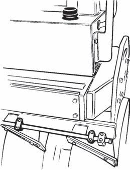
Instructions For Lifting
Before lifting the roller, the articulation must be locked to prevent inadvertent turning.
Turn the steering wheel so that the machine is set for driving straight forward. Push the reserve/parking brake knob.
Then pull down the bright galvanized locking bar (1) from its holder (3), and insert it from below into the hole in the lower articulation mount, push the bar through until its upper end is visible in the hole of the upper articulation mount.
Then secure the bar stud in position with the locking pin (2).
The maximum weight of the machine is noted on the hoisting plate (1). See also technical specifications in the maintenance instructions.
Lifting gear, such as chains, steel wires, straps, and lifting hooks must be dimensioned in conformance with current regulations.
Keep well clear of the hoisted machine! Make sure that hoisting hooks are securely anchored.
Remember to restore the locking bar (1) to its holder before driving again.
Instructions For Towing
Disengaging the brakes (Optional)
The following instructions apply to the CC102, CC122/122C and also the CC142C rear wheel motors.
Press the reserve/parking brake knob and stop the engine. Chock the drum so the roller does not begin to move on disengaging the brakes.
The disc brake in each drive motor must be disengaged mechanically, as described below, before the roller can be towed.
1. Use a swivel socket wrench with an 18 mm socket head.
2. Turn the disengagement screw (1) 1 1/2 turns clockwise to disengage the brake.
3. Disengage the brakes on both drums, or on the drum and the two rear wheel motors if it is a combo model.
4. After towing, turn the same screws 1 1/2 turns counter-clockwise to activate the brakes again.
Instructions For Towing
Disengaging the brakes
The following instructions apply to the CC142 and CC142C drums.
Press the reserve/parking brake knob and stop the engine.
Chock the drum so the roller does not begin to move on disengaging the brakes.
The disc brake in each drive motor must be disengaged mechanically, according to the following instructions, before the roller can be towed.
Restored brake
1. Remove the center plug (4) using a screwdriver.
2. Screw off the brake tool (1) from its threaded fixing hole. Then fix the brake tool (1) in the center hole by tightening the screw (2) until it bottoms in the hole. Tighten the nut (3) against the brake tool until it stops, indicating that the brake is now disengaged.
3. The rubber wheels are disengaged in the same way as for CC122C; see preceding page.
4. Screw out the nut again after towing. This returns the brakes to their normal mode. Screw off the brake tool and fit it back into its fixing hole. Refit the center plug (4) to counteract the formation of rust inside the threaded hole.
TOWING/RETRIEVAL
Towing a roller
The roller must be counter-braked when towing; use a towbar because the roller will have no braking ability.
The roller must be towed slowly (max. 3 km/h / 1.8 mph) and only a short distance (max. 300 m /275 yds).
When towing/retrieval a machine, the towing device must be connected to both lifting holes. The pulling forces must act longitudinally on the machine as illustrated. Maximum gross pulling force 130 kN.
Transportation
Roller
Interlock the articulation before hoisting and transportation; follow the instructions under the respective heading.
Chock the drums (1) and secure the chocks to the transport vehicle.
Block up under the drum frame (2), to avoid overload on the rubber suspension of the drum when lashing.
Clamp down the roller with lashing straps (3) at all four corners; decals indicate the fixing points.
Remember to restore the articulation interlock to open mode before starting the roller again.
The machine can be fitted with retractable ROPS.
Risk of being crushed when raising and lowering the exhaust pipe.
If the roller is equipped with a retractable protective structure, ROPS, then the machine may only be operated with the structure raised and locked in position.
To retract the protective structure, unscrew the securing screw (1), pull out the cotter pin (2) and pull out the bolt (3). Do this on both sides of the structure. If there is sufficient space the structure should preferably be retracted to the rear.
Restore the cotter pins and the bolts into position after retracting the structure.
Proceed in the reverse order to the above when raising the structure.
Always ensure that the structure is locked in its raised position before driving the roller.
Lubricate the securing screw (1) and the bolt (3) occasionally with waterproof grease.