11 minute read
MAINTENANCE

from Dana Spicer T12000 3,4,6-speed Intermediate Drop VDT12000 Transmission Service Manual 907397-b - PDF

Oil Specifications Recommended Lubricants
CUSTOMER OIL TYPE
CATERPILLAR TO-4.
JOHN DEERE J20 C. D.
MILITARY MIL-PRF-2104G.
ALLISON C-4.
DEXRON II Equivalent - See note below.
DEXRON* II EQUIVALENT IS ACCEPTABLE; HOWEVER IT IS NOT COMPATIBLE WITH TORQUE CONVERTERS OR TRANSMISSIONS EQUIPPED WITH GRAPHITIC FRICTION MATERIAL CLUTCH PLATES.
DEXRON* III, ENGINE OIL OR GL-5 OILS ARE NOT RECOMMENDED.
PREFERRED OIL VISCOSITY
It is recommended that the highest viscosity monograde lubricant available be used for the anticipated ambient temperature. Typically this will be a CAT TO-4 qualified lubricant. When large swings in ambient temperature are probable, J20 C, D multigrades are recommended. Multigrade lubricants should be applied at the lower viscosity rating for the prevailing ambient temperature, i.e. a 10W20 should be used where a 10W monograde is used. If a C-4 multigrade is used in stead of J20 lubricant it is recommended that the viscosity span no more than 10 points, i.e. 10W20.
SYNTHETIC LUBRICANTS ARE APPROVED IF QUALIFIED BY ONE OF THE ABOVE SPECIFICATIONS. OIL VISCOSITY GUIDELINES APPLY, BUT SYNTHETIC MULTIGRADES MAY SPAN MORE THAN 10 POINTS.
FOR FIRE RESISTANT FLUID RECOMMENDATIONS PLEASE CONTACT SPICER OFF-HIGHWAY PRODUCTS.
VALID FOR: VDT12000 & T12000
NORMAL OIL CHANGE INTERVAL
Drain and refill system every 1000 hours for average environmental and duty cycle conditions. Severe or sustained high operating temperature or very dusty atmospheric conditions will result in accelerated deterioration or contamination. Judgement must be used to determine the required change intervals for extreme conditions.
EXTENDED OIL CHANGE INTERVAL
Extended oil service life may result when using synthetic fluids. Appropriate change intervals should be determined for each transmission by measuring oil oxidation and wear metals, over time, to determine a baseline. Wear metal analysis can provide useful information but a transmission should not be removed from service based solely on this analysis.
VALID FOR: T12000
SUMP PREHEATERS
Preheat the transmission fluid to the minimum temperature for the oil viscosity used before engine start up.
FILTERS
Service oil filters element every 1000 hours under normal environmental and duty cycle conditions.
*Dexron is a registered trademark of GENERAL MOTORS CORPORATION.
T12000 - 3, 4, 6 speed
Maintenance Intervals
DAILY
Check oil level daily with engine running at idle (600 RPM) and oil at 82 - 93 °C (180-200 F).
Maintain oil level at full mark.
Normal Drain Period
Normal drain period and oil filter element change are for average environment and duty cycle condition.
Severe or sustained high operating temperature or very dusty atmospheric conditions will cause accelerated deterioration and contamination.
For extreme conditions judgement must be used to determine the required change intervals.
EVERY 1000 HOURS
Change oil filter element.
Drain and refill system as follows (Drain with oil at 65 - 93 °C (150 - 200 F)):
1 Drain transmission.
2 Remove and discard filter. Install new filter.
3 Refill transmission to FULL mark.
4 Run engine at 500 - 600 RPM to prime convertor and lines.
5 Recheck level with engine running at 500 - 600 RPM and add oil to bring level to FULL mark. When oil temperature is hot 82.2 - 93.3 °C (180- 200 F) make final oil level check and adjust if necessary to bring oil level to FULL mark.
NOTE
NOTE: IT IS RECOMMENDED THAT OIL FILTER BE CHANGED AFTER 100 HOURS OF OPERATION ON NEW, REBUILT OR REPAIRED UNIT.
Servicing Machine After Components Overhaul
The transmission, torque converter, and its allied hydraulic system are important links in the driveline between the engine and the wheels. The proper operation of either unit depends greatly on the condition and operation of the other. Therefore, whenever repair or overhaul of one unit is performed, the balance of the system must be considered before the job can be considered complete.
After the overhauled or repaired transmission has been installed in the machine, the oil cooler, and connecting hydraulic system must be thoroughly cleaned. This can be accomplished in several manners and a degree of judgement must be exercised as to the method employed.
The following are considered the minimum steps to be taken:
1 Drain entire system thoroughly.
2 Disconnect and clean all hydraulic lines. Where feasible hydraulic lines should be removed from machine for cleaning.
3 Replace oil filter element.
4 The oil cooler must be thoroughly cleaned. The cooler should be “back flushed” with oil and compressed air until all foreign material has been removed. Flushing in direction of normal oil flow will not adequately clean the cooler. If necessary, cooler assembly should be removed from machine for cleaning, using oil, compressed air, and steam cleaner for that purpose.
5 Reassemble all components and use only type oil (See chapter 4.1.1 “Recommended lubricants”). Fill the transmission through filler opening until fluid comes up to FULL mark on transmission dipstick.
NOTE: IF THE DIPSTICK IS NOT ACCESSIBLE OIL LEVEL CHECK PLUGS ARE PROVIDED.
–Remove check plug, fill until oil runs from oil hole. Relift filler and level plug.
–Run engine two minutes at 500 - 600 RPM to prime torque convertor and hydraulic lines.
–Recheck level of fluid in transmission with engine running at idle (500 - 600 RPM).
–Add quantity necessary to bring fluid level to FULL mark on dipstick or runs from oil level check plug hole.
–Install oil level plug of dipstick.
–Recheck with hot oil 82.2 - 93.3 °C (180 - 200 F).
–Adjust oil level to FULL mark on dipstick or runs freely from oil level plug.
6 Recheck all drain plugs, lines, connections, etc.…, for leaks and tighten where necessary.
VDT12000
MAINTENANCE INTERVALS FOR THE 3 & 4 SHAFT DROP BOX
DAILY
Check oil level daily. Maintain oil level at full mark. (Middle of oil level glass)
NORMAL DRAIN PERIOD
Normal drain period is every 1000 hours for average environment and duty cycle condition. Severe or sustained high operating temperature or very dusty atmospheric conditions will cause accelerated deterioration and contamination. For extreme conditions judgement must be used to determine the required change intervals.
MAINTENANCE INTERVALS FOR THE TRANSMISSION.
TO DRAIN THE TRANSMISSION, BOTH DRAIN PLUGS (A & B) NEED TO BE REMOVED NOTE
Undo the lock nuts (9) securing the runner pins (10). Remove the runner pins (10), holding the lock nuts (9) in position.
5
6
7
8
9
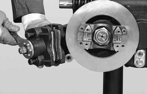
Move towards the external part of the brake caliper (7) the screws (9) complete with sleeves (3) and lock nuts (8) to facilitate the brake caliper (7) installation.
10
Insert
11
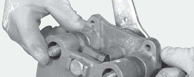
Remove the backlash between screws (9) and sleeves (3) working on the lock nuts (8). Send the screws (9) to end stroke, complete with sleeves (3) and lock nuts (8).
12
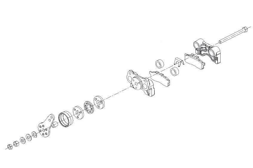
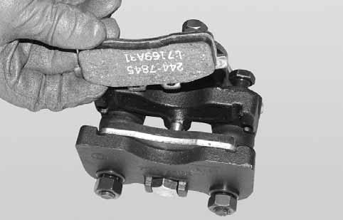
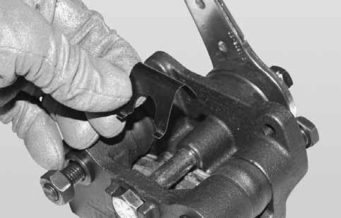
BRAKE CALIPER BACKLASH REGULATION
Repeat the operation on both screws. Holding the lock lock nut in position, unloose the screw of about 1 turn.
13
Repeat the operation on both screws. Using a screwdriver adjust the sleeve (3) as shown in picture.
14
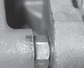
Repeat the operation on both screws. Insert a 0,7 mm shim between the sleeve (3) and the lock nut (8) to check the brake caliper (7) backlash.
NOTE: Check that the lock nut (8) is at end of stroke.
15
Repeat the operation on both screws. Keeping the shim in position, insert the screw (9) to regulate the backlash between sleeve (3) and lock nut (8).
16
Repeat the operation on both screws. Keeping the screws (9) in position, torque the lock nuts (8) to a tightening torque of 108 - 119 Nm.
17
Brake Pads Backlash Adjustment
Loosen and remove the brake pads (4) outer adjustment nut (1).
18
Tighten the inner adjustment nut (2) until firm contact is made with the disc by the pads (4). Using a dynamometric wrench tighten the nut to a tightening torque of 11 Nm.
19
Loosen the inner adjustment nut (2) by 4-5 surfaces. Check the correct working of the brake caliper (7). 20
Screw the outer nut (1) on the adjustment bolt (6). Keeping the inner nut (2) in position, torque the outer nut (1) to a tightening torque of 60 - 75 Nm.
Troubleshooting Guide
T12000 - 3, 4, 6 speed
The following information is presented as an aid to isolating and determining the specific problem area in a transmission that is not functioning correctly. When troubleshooting a “transmission” problem, it should be kept in mind that the transmission is only the central unit of a group of related powertrain components. Proper operation of the transmission depends on the condition and correct functioning of the other components of the group. Therefore, to properly diagnose a suspected problem in the transmission, it is necessary to consider the transmission fluid, charging pump, torque converter, transmission assembly, oil cooler, filter, connecting lines, and controls, including the engine, as a complete system. By analysing the principles of operation together with the information in this section, it should be possible to identify and correct any malfunction which may occur in the system.
T12000 Transmission
T12000 (power shift with torque converter transmission) troubles fall into three general categories:
1 Mechanical problems.
2 Hydraulic problems.
3 Electrical problems.
In addition to the mechanical and electrical components, all of which must be in the proper condition and functioning correctly, the correct functioning of the hydraulic circuit is most important. Transmission fluid is the “life blood” of the transmission. It must be supplied in an adequate quantity and delivered to the system at the correct pressures to ensure converter operation, to engage and hold the clutches from slipping, and to cool and lubricate the working components.
Troubleshooting Procedures
STALL TEST
A stall test to identifies transmission, converter, or engine problems. Use following procedure:
1 Put the vehicle against a solid barrier, such as a wall, and/or apply the parking brake and block the wheels.
2 Put the directional control lever in FORWARD (or REVERSE, as applicable).
3 Select the highest speed. With the engine running, slowly increase engine speed to approximately one-half throttle and hold until transmission (converter outlet) oil temperature reaches the operating range.
DO NOT OPERATE THE CONVERTER AT STALL CONDITION LONGER THAN 30 SECONDS AT ONE TIME, SHIFT TO NEUTRAL FOR 15 SECONDS AND REPEAT THE PROCEDURE UNTIL DESIRED TEMPERATURE IS REACHED.
EXCESSIVE TEMPERATURE 120 °C (250 F) MAXIMUM WILL CAUSE DAMAGE TO TRANSMISSION CLUTCHES, FLUID, CONVERTER, AND SEALS.
Transmission Pressure Checks
Transmission problems can be isolated by the use of pressure tests. When the stall test indicates slipping clutches, then measure clutch pack pressure to determine if the slippage is due to low pressure or clutch plate friction material failure.
In addition, converter charging pressure and transmission lubrication pressure can also be measured.
Mechanical And Electircal Checks
Prior to checking any part of the system for hydraulic function (pressure testing), the following mechanical and electrical checks should be made:
•Check the parking brake and inching pedal for correct adjustment.
•Be sure all lever linkage is properly connected and adjusted in each segment and at all connecting points.
•The controls are actuated electrically. Check the wiring and electrical components.
•Be sure that all components of the cooling system are in good condition and operating correctly. The radiator must be clean to maintain the proper cooling and operating temperatures for the engine and transmission. Air clean the radiator, if necessary.
•The engine must be operating correctly. Be sure that it is correctly tuned and adjusted to the correct idle and maximum no-load governed speed specifications.
HYDRAULIC CHECKS
Also, before checking the transmission clutches, torque converter, charging pump, and hydraulic circuit for pressure and rate of oil flow, it is important to make the following transmission fluid check: Check oil level in the transmission. The transmission fluid must be at the correct (full level). All clutches and the converter and its fluid circuit lines must be fully charged (filled) at all times.
THE TRANSMISSION FLUID MUST BE AT OPERATING TEMPERATURE OF 82 - 93 °C (180 - 200 F) TO OBTAIN CORRECT FLUID LEVEL AND PRESSURE READINGS. DO NOT ATTEMPT TO MAKE THESE CHECKS WITH COLD OIL.
To raise the oil temperature to this specification it is necessary to either operate (work) the vehicle or run the engine with converter at “stall” (Refer to 7.2.1 “Stall test”).
BE CAREFUL THAT THE VEHICLE DOES NOT MOVE UNEXPECTEDLY WHEN OPERATING THE ENGINE AND CONVERTER AT STALL RPM.
Troubleshooting Guide
Refer to the following troubleshooting guide for the diagnosis of typical transmission troubles.
LOW CLUTCH PRESSURE
CAUSE REMEDY
Low oil level. Fill to proper level.
Clutch pressure regulating valve stuck open. Clean valve spool and housing.
Faulty charging pump. Replace pump.
Broken or worn clutch shaft or piston sealing rings. Replace sealing rings.
Clutch piston bleed valve stuck open. Clean bleed valves thoroughly.
LOW CHARGING PUMP OUTPUT
CAUSE REMEDY
Low oil level. Fill to proper level.
Suction screen plugged. Clean suction pump.
Defective charging pump. Replace pump.
Overheating
CAUSE REMEDY
Worn oil sealing rings. Remove, disassemble, and rebuild converter assembly.
Worn charging pump. Replace charging pump.
Low oil level. Fill to proper level.
Dirty oil cooler. Clean cooler.
Restriction in cooler lines. Change cooler lines.
NOISY CONVERTER
CAUSE REMEDY
Worn charging pump. Replace charging pump.
Worn or damaged bearings. A complete disassembly will be necessary to determine which bearing is faulty.
LACK OF POWER
CAUSE REMEDY
Low engine RPM at converter stall. Tune engine check governor. See “Overheating” and make same checks. Make corrections as explained in “Overheating”.
Check Points
TROUBLESHOOTING GUIDE
T12000
TROUBLESHOOTING GUIDE
Electrical Wiring
SPICER OFF-HIGHWAY WILL NOT SUPPLY ITEMS INDICATED WITH
STANDARD 4-SPEED TRANSMISSION (1-3-5 6 SPEED)
SPICER OFF-HIGHWAY WILL NOT SUPPLY ITEMS INDICATED WITH
TO WIRE CONNECTOR NO. 7
TROUBLESHOOTING GUIDE
T12000 - 3, 4, 6 speed
ALTERNATIVE
4-SPEED TRANSMISSION (1-3-4-5 6 SPEED)
NOTE: ALTERNATIVE 4-SPEED TRANSMISION IS ONLY AVAILABLE WITH EGS OR APC.
ELECTRIC SOLENOID CONTROL WIRING DIAGRAM FOR ALTERNATIVE 4-SPEED TRANSMISSION: REFER TO WIRING DIAGRAM OF CORRESPONDING CONTROLLER.
6-SPEED TRANSMISSION
SPICER OFF-HIGHWAY WILL NOT SUPPLY ITEMS INDICATED WITH
SPEED SENSOR - STATIC STANDALONE TEST
In order to be able to sense the currents, a series resistor of e.g. 200 Ohms must be used. This resistor is integrated in the controller, but when the sensor is to be tested, it must be connected externally. The idea is to connect the sensor to an external power source and measure the DC voltage across the series resistor. The voltage reading should be either 1.2V-1.6V (for the 7mA ± 1mA current level) or 2.6-3.0V (for the 14mA ± 1mA current level)
If the teeth can be moved slowly, distinct toggling between the two levels should be noticed.
VDT 12000
CHECK POINTS
TRANSMISSION WITH A 3 SHAFT DROP BOX
TRANSMISSION WITH A 3 SHAFT DROP BOX
TRANSMISSION WITH A 4 SHAFT DROP BOX
TRANSMISSION WITH A 4 SHAFT DROP BOX
Vdt 17 Degrees
Check Points
Sectional Views And Parts Identification
GROUP -TRANSMISSION CASE AND PLATE
GROUP - TORQUE CONVERTER
GROUP - PUMP DRIVE
GROUP - CHARGING PUMP
GROUP - REVERSE IDLER
GROUP - FORWARD AND REVERSE SHAFT
GROUP - 3RD SHAFT (FOR 3-SPEED TRANSMISSION ONLY)
GROUP - HIGH (4TH) AND 3RD SHAFT
GROUP - 1ST AND 2ND SHAFT
GROUP - OUTPUT SHAFT (REAR ONLY)
GROUP - OUTPUT SHAFT (FRONT ONLY)
GROUP - OUTPUT SHAFT (FRONT & REAR)
GROUP - DISK BRAKE
GROUP - CALIPER ASSEMBLY
GROUP - ELECTRIC CONTROL
* Quantity = 4, with 3-speed. ** Used with 3-speed only.
GROUP - DRIVE PLATE
Vdt 12000
CASE & PLATE GROUP
3 Shaft Drop Box Group
4 Shaft Drop Box Group
T12000 Installation Details
Converter Drive Coupling
Measure the “A” dimension (bolt circle diameter) and order drive plate kit listed below. Note three (3) kits have two (2) intermediate drive plates and one (1) drive plate and weld nut assembly. Three (3) kits with three intermediate drive plates.
(1) ALIGNMENT HOLES
DRIVE PLATE AND WELD NUT ASSEMBLY
(2) INTERMEDIATE DRIVE PLATES
NOTE: TO FACILITATE ASSEMBLY, ALIGN SMALL HOLES IN DRIVE PLATES - SEE ILLUSTRATION ABOVE - ALIGNMENT HOLES.
Position drive plate and weld nut assembly on torque converter assembly with weld nuts toward converter. Align intermediate drive plates and backing plate with holes in torque converter assembly.