2 minute read
System Diagrams

System Diagrams - Overview
General Information
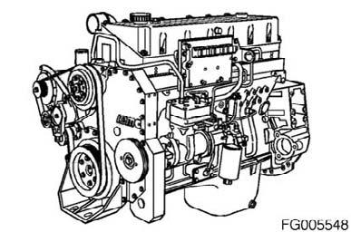
The following drawings show the flow through the engine systems. Although parts can change between different applications and installations, the flow remains the same. The systems shown are: • Fuel System • Lubricating Oil System • Coolant System • Intake Air System • Exhaust System Knowledge of the engine systems can help you in troubleshooting, service, and general maintenance of your engine.
QSM11 Cummins Engine QSM11CUMMINSENG Page 119
Industrial Drive
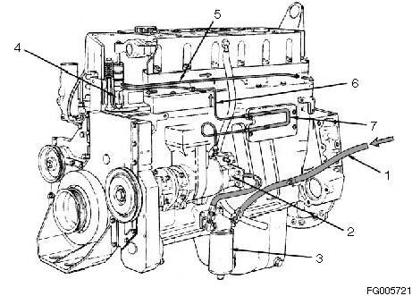
Figure 248
Reference Number Description
1 Fuel Inlet Supply 2 Fuel Pump 3 Fuel Filter 4 Injector 5 Fuel Drain Return 6 Fuel to Injector 7 ECM Cooling Plate
Reference Number Description
QSM11 Cummins Engine Page 120 QSM11CUMMINSENG
Flow Diagram
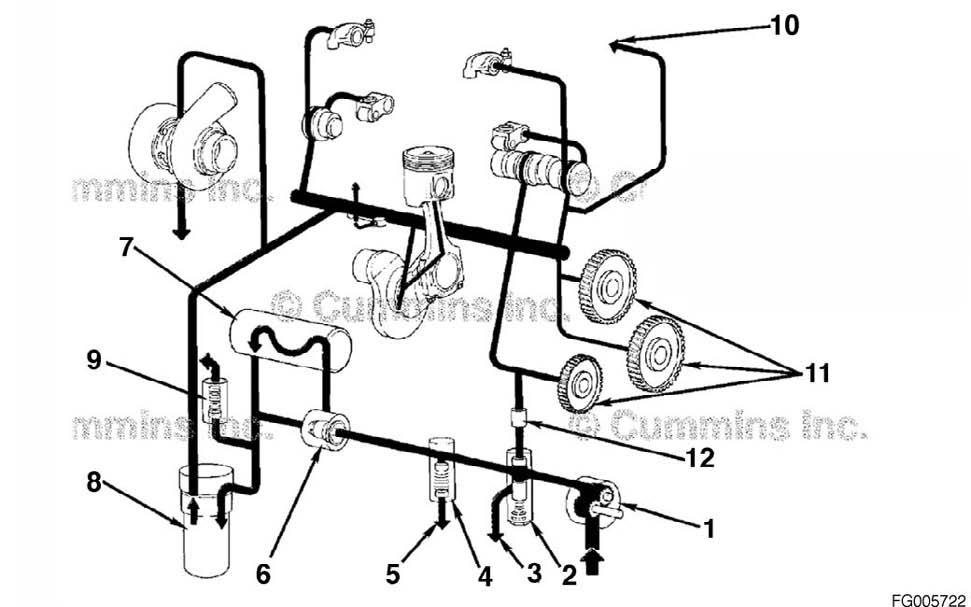
Figure 249
Reference Number Description
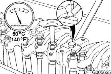
1 Oil Pump 2 Pressure Regulator Valve 3 Oil Return to Pan 4 High-pressure Relief Valve 5 Oil Return to Pan 6 Oil Thermostat 7 Oil Cooler 8 Combination Oil Filter 9 Filter Bypass Valve 10 Accessory Drive or Air Compressor 11 Idler Gears 12 Viscosity Sensor
Reference Number Description
QSM11 Cummins Engine QSM11CUMMINSENG Page 121
Flow Diagram

Figure 250
Reference Number Description
1 Water Pump Coolant Inlet 2 Coolant to Lower Manifold Cavity 3 Coolant to Cylinder Liner Block Cavity 4 Coolant to Cylinder Head 5 Coolant to Upper Manifold Cavity 6 Lower Manifold Coolant to Oil Cooler 7 Oil Cooler to Upper Manifold Cavity
Reference Number Description
QSM11 Cummins Engine Page 122 QSM11CUMMINSENG

Figure 251 Open (1-5), Closed (6-9)
Reference Number Description
1 Water Pump Coolant Inlet 2 Upper Manifold Cavity (Coolant To Thermostat) 3 Coolant Outlet 4 Lower Manifold Cavity to Cooler 5 Cooler to Upper Manifold Cavity (Before Thermostat) 6 Upper Manifold Cavity (Coolant to Thermostat) 7 Coolant Bypass (Return to Water Pump) 8 Lower Manifold Cavity to Cooler 9 Cooler to Upper Manifold Cavity (Before Thermostat)
Reference Number Description
QSM11 Cummins Engine QSM11CUMMINSENG Page 123
Industrial Drive
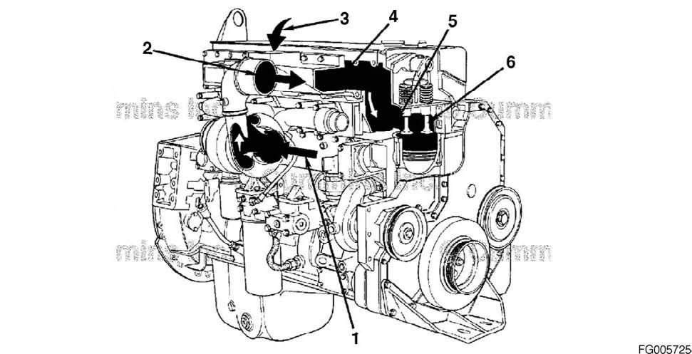
Figure 252
Reference Number Description
1 Filtered Intake Air to Turbocharger 2 Turbocharger Air to Charge Air Cooler 3 Charge Air Cooler Intake Air to Intake Manifold 4 Intake Manifold 5 Intake Valve Ports 6 Intake Valves
Reference Number Description
QSM11 Cummins Engine Page 124 QSM11CUMMINSENG
Industrial Drive
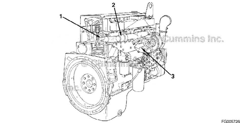
Figure 253
Reference Number Description
1 Exhaust Valve Ports 2 Exhaust Manifold 3 Turbocharger Exhaust Outlet
Reference Number Description
QSM11 Cummins Engine QSM11CUMMINSENG Page 125
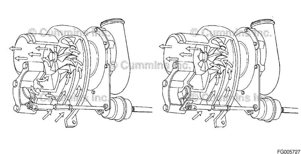
Figure 254 Wastegate Actuation OPEN and CLOSED