7 minute read
Breather or filler cap


BREATHER CAP - This cap acts as a filter to clean the air which surges into and out of an engine when it is operating. To remove dust and dirt from the air drawn in on the inward surge, the screen must be kept clean and covered with oil. It should be inspected and if dirt is present, the cap should be washed in gasoline, then dipped in engine oil, excess oil shaken off, and the cap put in place again.
CHASSIS LUBRICATION
At least once a year, or every 1000 hours, drain transmission compartments by removing the three plugs, 21 and 22, on the lubrication chart. Preferably the draining should be done while the tractor is warm. The transmission will require 4%, Imperial gallons (5 U.S. gallons) to fill and the pulley housing I%, Imperial gallons (2 U.S. gallons). After filling the transmission do not use the creeper with the shift in the low speed (lever towards the rear) until the tractor has been operated for about one hour or so, asthis chamber is filled from the transmission by splash. If the tractor is operated at very low temperature the pulley housing and transmission lubricant may be thinned with one half gallon of kerosene, but before using in warm weather this thinned mixture MUST be drained and replaced by new oil.
QUALITY OF LUBRICANT - Use a good grade of mineral oil made by a reputable manufacturer as the best assurance of trouble-free service. SAE 90 transmission lubricant can be used both winter and summer.
FRONT WHEEL BEARINGS - To provide satisfactory lubrication to the front wheel bearings remove wheels, clean and repack with wheel bearing grease periodically.
PRESSURE GUN LUBRICATION - Use a good quality grease, not one that will thin out under load and moderate temperatures. Keep the grease and the gun clean clean each fitting before use and force enough lubricant into fitting to insure a fresh supply to the wearing surfaces.
INSTRUMENT PANEL
AND CONTROLS Operating Instructions for Cockshutt "30" Tractor •
)} ) /:J 7 / I PLATE
No.
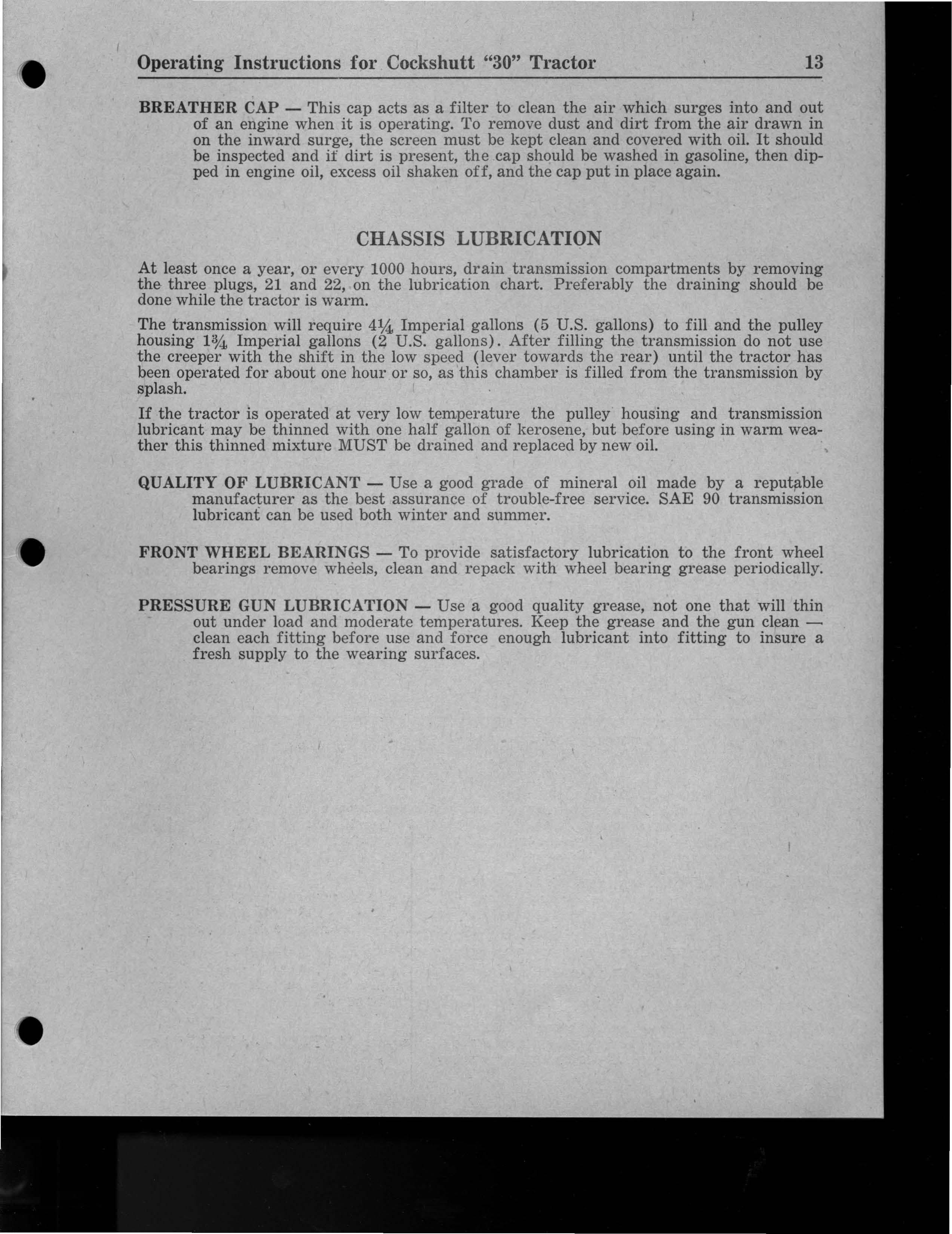
INSTRUMENT PANEL AND CONTROLS
PLATE No. C·8-46 CHOKE LEVER - as indicated by arrow (1) This control near the upper right cover of the instrument panel is held in the open position by spring pressure and shoul d be used only when starting. The spring loaded feature prevents undue choking and unnecessary engine wear and excessive fuel consumption. IGNITION SWITCH - as indicated by arrow (2) Duplicate keys are provided and should be removed to prevent loss, theft or tampering with the tractor by unauthorized persons. Turn to right when ready to start the engine - to the left or upright position when it is desired to stop the engine. LIGHT SWITCH and GENERATOR CONT ROL SWITCH - as indicated by arrow (3) This is combined into one and has three positions: (a) full in-low rate charge; (b) half out-high rate charge; (c) full out-lights on and generator full charge. (See further instructions under Wiring Diagam on page 22. STARTER SWITCH - as indicated by arrow (4) This is pushed when one desires to start the engine. CAUTION - ALWAYS have gear shift in neutral position when starting.

OIL GAUGE - as indicated by arrow (5) This shows the pressure in the oil lines leading from the pump to the engine bearings and should be watched every time the engine is started. Pressure should be between 20 to 25 pounds. If not between these pressures check the oil level, and if below the "low" mark, check for leaks in the oil lines to the filter and gauge. If there are none, a qualified mechanic should be consulted and the engine should not be run until corrected. AMMETER - as indicated by arrow (6) With the light switch half out (first notch past full-in) the ammeter should show from 10 to 15 amperes charge. INSTRUMENT PANEL LIGHT - as indicated by arrow (7) The switch on the panel light will turn the light on only when the ignition switch is turned to allow operation without the headlights being on and also to prevent being left on when the tractor is not in operation. BRAKE PEDALS AND INTERLOCKING PIN - as indicated by arrow (8) The brake pedals should be used to stop the tractor, hold the tractor in a stationary position, and to assist in making sharp turns as outlined below: (1) To stop the tractor, the pedals should be locked together so both brakes will operate simultaneously. (2) To hold the tractor in a stationary position, lock the pedals together, depress and lock them in the depressed position using the brake pedal lock. (3) To assist in making a sharp turn, the pedals must be operated individually, depressing the pedal on the side toward which the turn is to be made. CAUTION - Always lock pedals together by means of the sliding pin, when travelling on the road in fourth speed. BRAKE PEDAL LOCK - as indicated by arrow (9) This is shoved down while one's foot is being removed from the brake pedals to lock the pedals down and thus prevent the tractor from moving. ENGINE SPEED CONTROL LEVER - as indicated by arrow (10) Through the governor this lever, when adjusted to the desired speed, keeps the engine speed uniform under varying load conditions. CLUTCH PEDAL - as indicated by arrow (11) When depressed all the way this pedal disengages the transmission from the engine. CAUTION - Do NOT operate tractor with foot resting on clutch pedal. HEAT INDICATOR - As indicated by arrow (12) . This instrument indicates the temperature of the liquid in the cooling system. CAUTION - Do not operate the tractor with the cooling liquid boiling. Operation of the tractor at this temperature will result in-damage to the engine. GEAR SHIFT LEVER - As indicated by arrow (13). This is of an automotive type.
CONSTRUCTION - The engine is a heavy duty, 4 cylinder, valve in head, wet sleeve motor with a pressure oiling system as described in detail on page 12. A water pump is used with a full flow by-pass thermostat to insure constant motor temperature which is so important in securing long life from the wearing parts. All working parts are protected by the large capacity oil filter used, the heavy duty air cleaner, and the careful sealing of the main bearings at the front and rear of the crankshaft. The high quality variable speed governor provides constant engine speed control. The main connecting rod bearings are of high precision, interchangeable, steelbacked babbit design. SERVICE - It is strongly recommended that, should any work have to be done on the motor, it be taken to your dealer. YouI' dealer has the proper facilities and the trained personnel to give your tractor the efficient attention that it deserves.
VALVE ADruSTMENT
3
No. C·21-46 VALVE TAPPET ADJUSTMENT
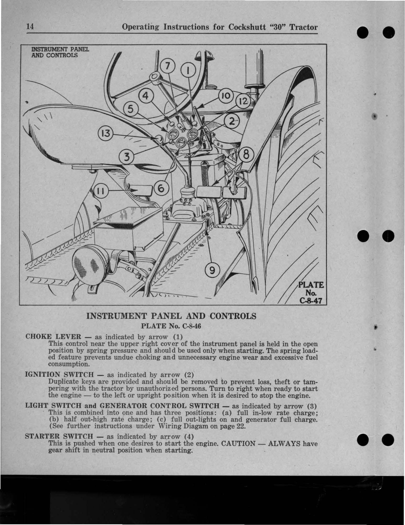
PLATE No. C-21-t6 Every 400 hours or once a year, it is recommended that a competent mechanic check the tappet clearance. A clearance of .009" is necessary between end of rocker arms and valve stems when valves are closed and the engine is warm. (1) Before checking valve clearance, make sure ignition switch is off. This eliminates danger of accidently starting the engine. (2) Remove valve cover.
(3) Crank the engine slowly, watching No.4 cylinder valves. When the exhaust valve is just closed and the intake valve is just starting to open, No.1 cylinder is at top dead centre on the compression stroke - and both valves are closed. (4) Loosen the lock nut as indicated by arrow (1) and adjust screw as indicated by arrow (2) in rocker arm so that a .009" feeler gauge as indicated by arrow (3) slips snugly between end of rocker arm and the valve stem. (5) Tighten lock nut and recheck clearance. Check both intake and exhaust valves on cylinder.
, (6) Crank engine 1f2 revolution at a time and check clearance of each cylinder's valves and adjust as instructed above. Do this on each set of cylinder valves in succession according to the firing order of the engine, which is 1, 3, 4, 2, as shown on Plate No.
C-20-46 on page 26. (7) Replace valve cover. Check to make sure the valve cover gasket makes an oil-tight seal with the cylinder head. Replace the gasket, if necessary, with a new one.