2 minute read
Remove the tie rods (E1) and the nuts (E2) which secure the two section loader control valve (A) .

from CNH Hydraulic system kit for 4x1 bucket (machines with power shuttle and gear pump) B100B B100BLR B1

4 - ASSEMBL Y
HYDRAULIC SYSTEM FOR 4X1 BUCKET
Installation hydraulic system for 4X1 bucket
Mandatory Declaration Conformity updates
NOTE: The hydraulic fluid will released during this procedure, prepared direct the fluid into the suitable container and dispose properly . NOTICE: A void the contamination, clean all the connections before disconnecting the tubes, the hoses, the connectors. Cap plug all the ports after disconnecting. A TTENTION: The dealer the person who guarantees for the correct installation the “4X1 bucket hydraulic system” must certify the correct assembly the Manufacturer , in order ask for the update the EC Declaration Conformity .
Refer the service manual and remove / lift the cab if necessary .
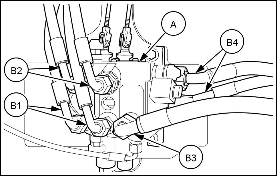
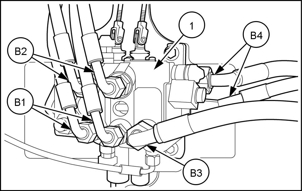
Identify and disconnect the hoses (B1) from the two section loader control valve (A) .
Identify and disconnect the hoses (B2) from the two section loader control valve (A) .
Identify and disconnect the hose (B3) from the two section loader control valve (A) .
Identify and disconnect the hoses (B4) from the two section loader control valve (A) .
RAIL16TLB1417AA 1
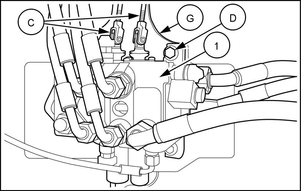
Identify and disconnect the control links (C) from the two section loader control valve (A) . Remove the bolts (D) . Retain the bolts (D) for reuse. Remove the two section loader control valve (A) from the machine.
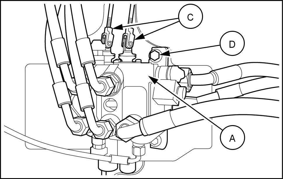
RAIL16TLB1417AA 2
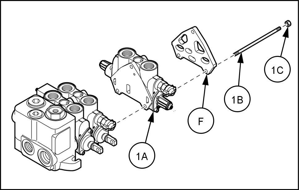
10. Remove the tie rods (E1) and the nuts (E2) which secure the two section loader control valve (A) . 1 Remove the cover plate (F) . 12. Retain the cover plate (F) for reuse.
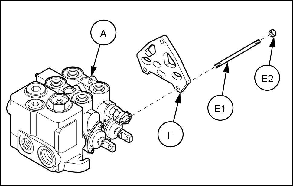
RAIL16TLB1419AA 3
13. Install the third spool control valve (1A) with the tie rods (1B) . NOTE: not move the valves prevent damage the
Orings. 14. Install the cover plate (F) removed earlier . 15. Secure the cover plate (F) with the nuts (1C) .
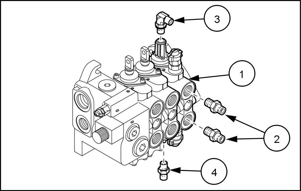
16. Install the adapters (2) into the three spool loader control valve (1) ports shown. 17. Install the elbow fitting (3) into the port the top the three spool loader control valve (1) shown. 18. Install the connector (4) into the port the bottom the three spool loader control valve (1) shown.
19. Install the three spool loader control valve (1) onto the support (G) with the bolts (D) removed earlier . 20. Identify and connect the control links (C) onto the three spool loader control valve (1) .
21. Identify and connect the hoses (B2) its correct ports the three spool loader control valve (1) . 22. Identify and connect the hoses (B1) its correct ports the three spool loader control valve (1) . 23. Identify and connect the hoses (B4) its correct ports the three spool loader control valve (1) . 24. Identify and connect the hose (B3) its correct port the three spool loader control valve (1) .
RAIL16TLB1418AA 4
RAIL16TLB1420AA 5
RAIL16TLB1421AA 6
RAIL16TLB1421AA 7