9 minute read
a torque - N·m ( 22.1 29

from CNH 1021F 1121F W270C W300C Wheel Loader Cold Start Grid Heater Installation Instructions Manual

Installing Grid Heater Kit Components
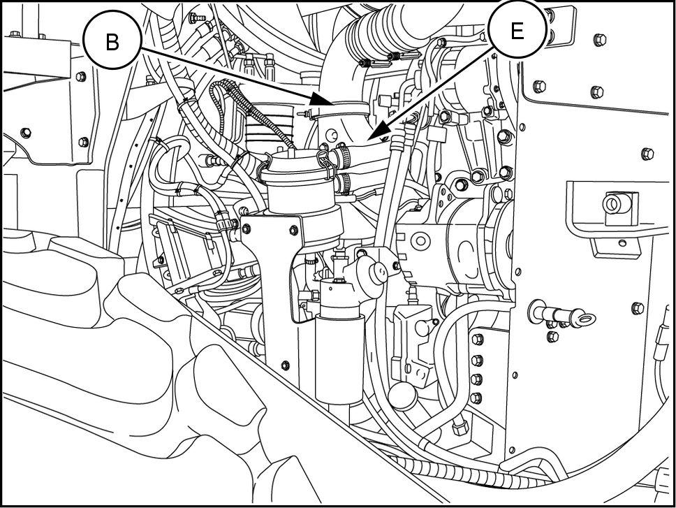
Remove clamp (B) from top intake manifold (E) . Save clamp and gasket for reuse later .
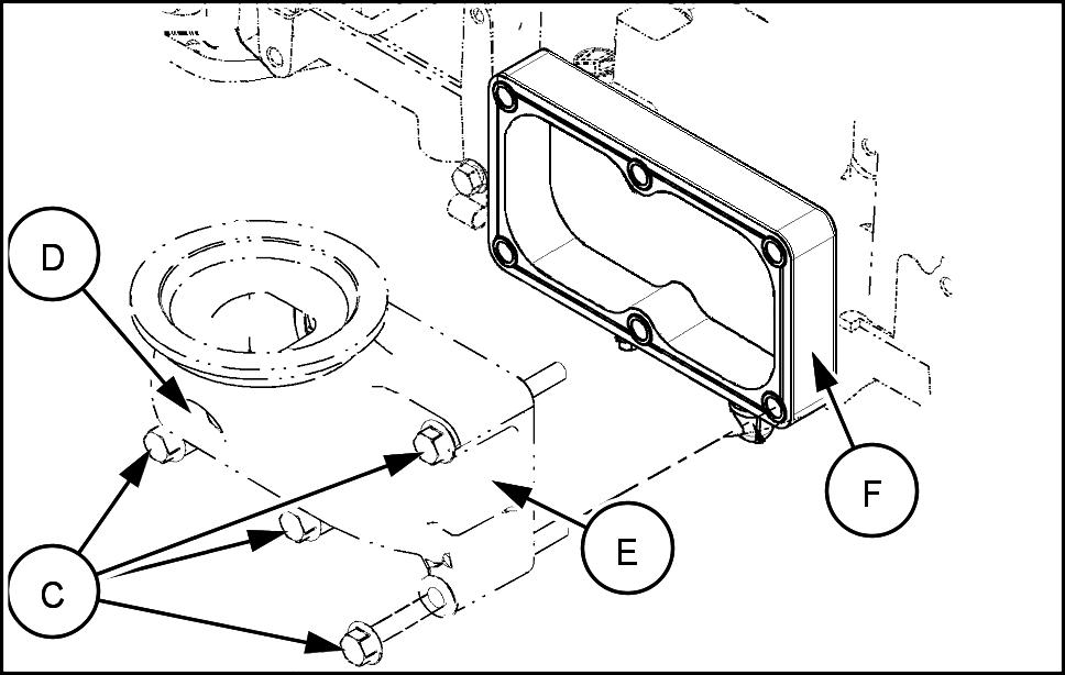
Remove five M10 x 100 bolts (C) and one M10 x 150 bolt (D) from the intake manifold (E) . Remove the grid heater spacer (F) and two gaskets. Save the bolts for reuse.
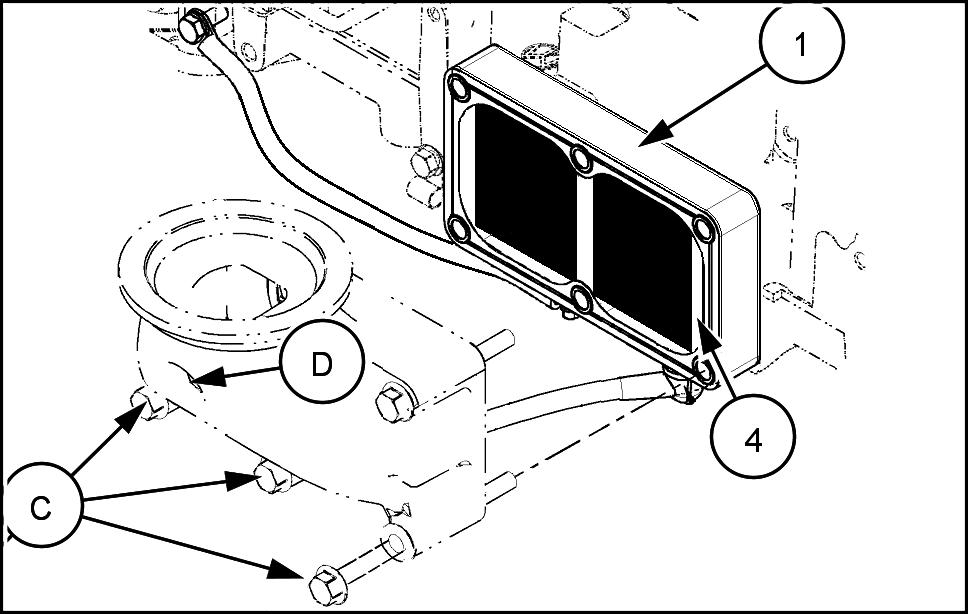
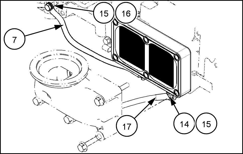
Install grid heater (1) with the terminals toward the bottom. Place the direction flow arrow the bottom the heater towards the engine. Install one new gasket (4) each side the grid heater . Secure these parts with five M10 X 100 bolts (C) and one M10 X 150 bolt (D) . Install the longer bolt in the top center location. T orque bolts - N·m ( 33.2 40.6 ).
Connect one end the long grid heater relay heater power cable (17) the right terminal the bottom the heater . Secure the cable with one nut (14) and two 9 x x 1.6 washers (15) . Connect one end the grid heater ground cable (7) the left terminal the bottom the grid heater . Secure the cable with one nut and two 6.6 x 12.5 x 1.6 washers (10) . Secure the other end the grid heater ground cable (7) the engine with one X bolt (16) and one 9 x 6 x 1.6 washer (15) . Remove paint prior assembly .
RCPH1 1WHL294AAH 3
RAIL12WEL0832AA 4
RAIL12WEL0833AA 5
RAIL12WEL0833AA 6
Install the gasket removed earlier between the air intake tube and the top the intake manifold (E) . Secure the tube the top the intake manifold with the clamp (B) removed earlier .
RCPH1 1WHL294AAH 7
NOTE: Assure that all gaskets are in proper location prevent dirt intake.
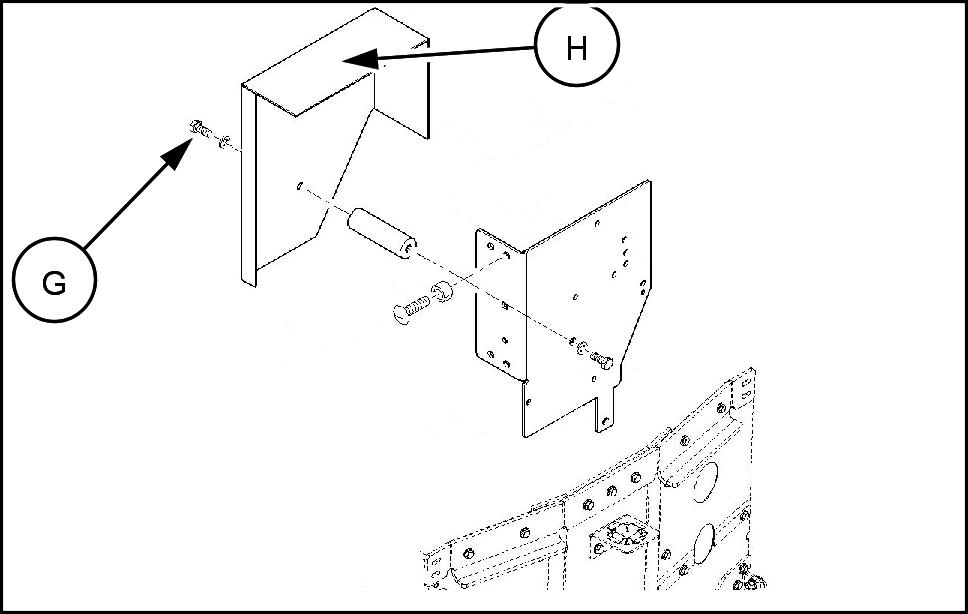
Remove one bolt (G) from the relay mounting plate cover the firewall the left front the engine. Remove the cover (H) .
RAIL12WEL0863AA 8
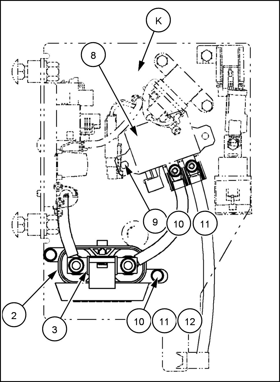
Mount the fuse block (2) and fuse (3) the relay mounting plate (K) with two x bolts (12) , two nuts and four 6.6 x 12.5 x 1.6 washers (10) .
RAIL12WEL0866BA 9
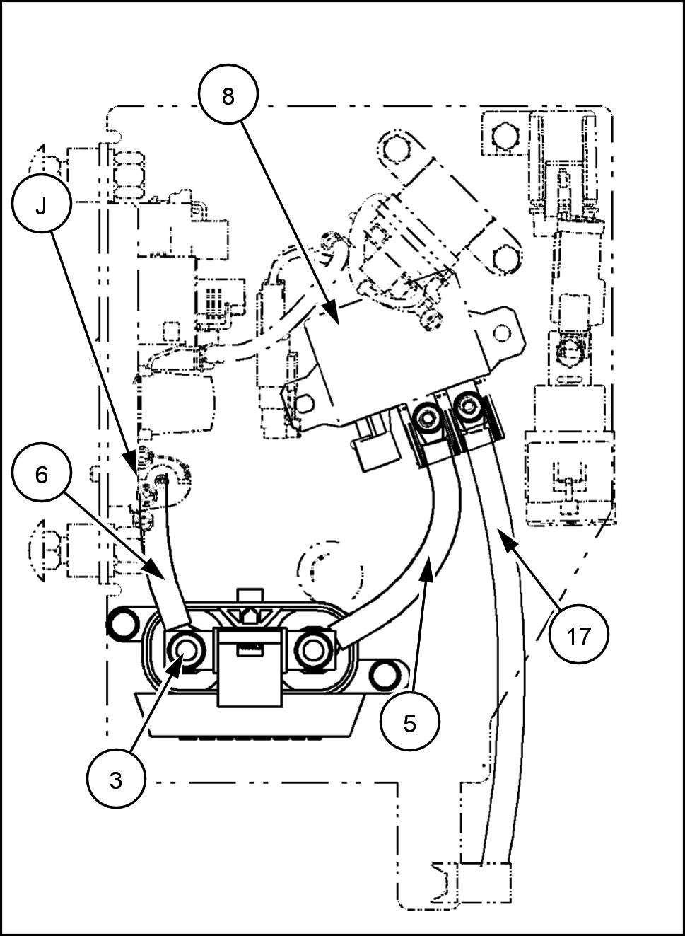
NOTE: Parts removed from graphic for clarity . Position the cables shown. 10. Mount the power relay (8) the relay mounting plate (K) with two x bolts (9) , two nuts , and two 6.6 x 12.5 x 1.6 washers (10) . 1 Connect harness connector GHC the power relay (8) . 12. Connect one end the shortest power B+ fuse cable (6) the power terminal the bottom the power relay module (J) . 13. Connect the other end the power B+ grid heater fuse cable (6) the left terminal the 200 amp fuse (3) . 14. Connect one end the grid heater fuse power relay cable (5) the right terminal the 200 amp fuse (3) 15. Connect the other end the grid heater fuse power relay cable (5) the left terminal the grid heater power relay (8) . T orque the nuts 4.0
5.0
N·m ( 3.0 3.7 ). 16. Connect the open end the grid heater power relay grid heater cable (17) the right terminal the power relay (8) .
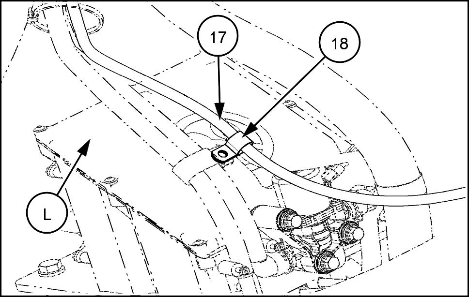
17. Smoothly route the grid heater power relay heater cable (17) between the relay and the heater . Secure the cable the top the DEF fluid supply module (L) with the clamp (18) . Secure the clamp with the existing hardware.
RAIL12WEL0866BA 10
RAIL12WEL0865AA 11
18. Install the relay mounting plate cover (H) . Secure the cover with one bolt (G) .
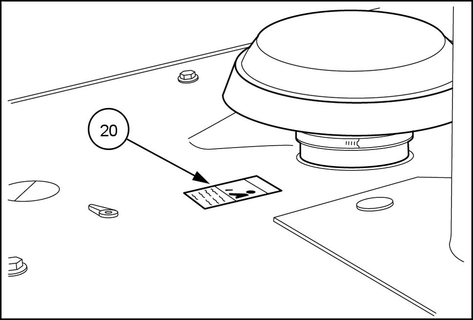
19. Place one ether warning safety decal (20) near the fresh air intake for the engine.
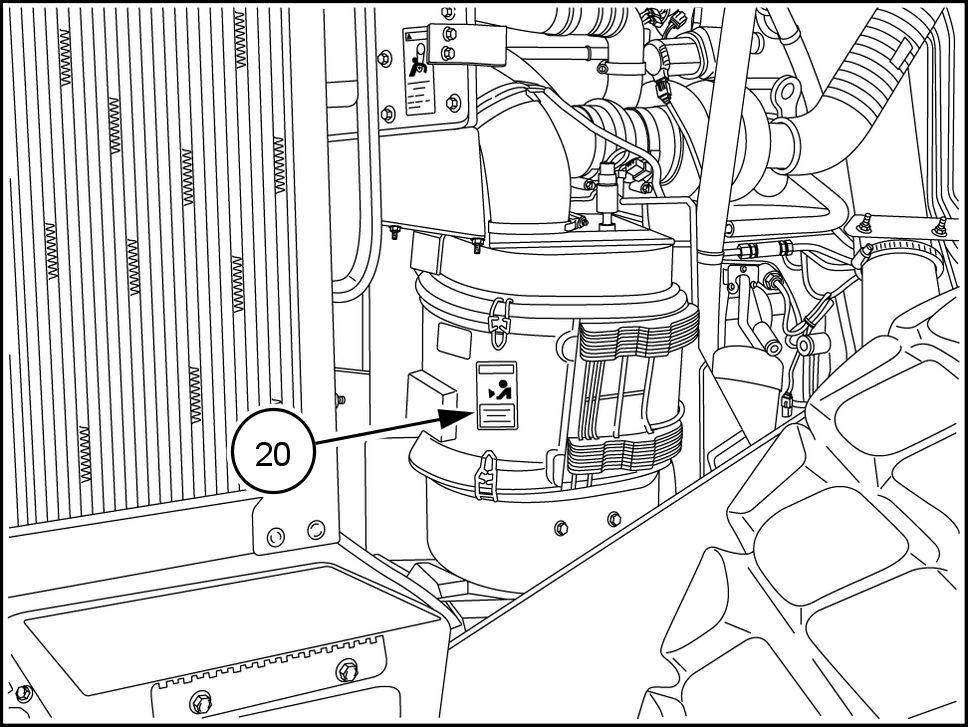
20. Place one ether warning safety decal (20) the air cleaner housing the right side the engine.
RAIL12WEL0863AA 12
RCPH1 1WHL275AAH 13
RCPH1 1WHL077AAH 14
Installing Fuel Filter W ith Heater Kit Components
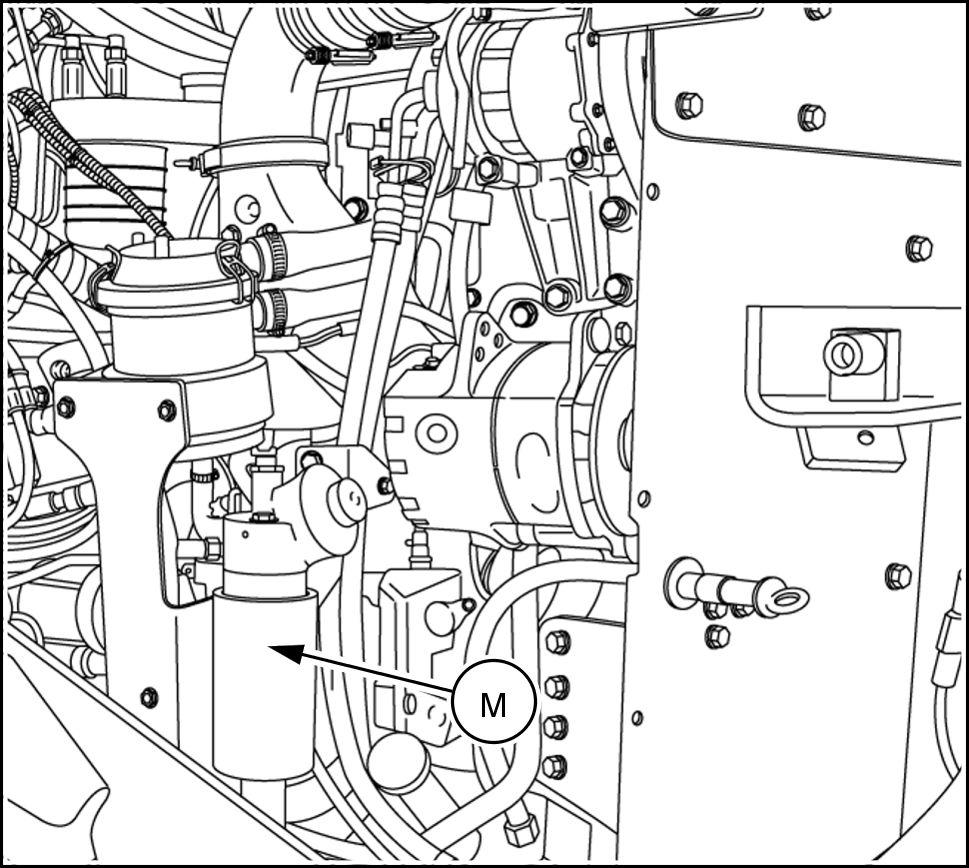
Remove WIF sensor connector from the bottom the fuel filter (M) . Open the bleeder the bottom the filter . Drain into a suitable container . Remove fuel lines from the filter head. Remove the fuel filter assembly (M) . Save the mounting hardware for reuse.
RCPH1 1WHL308AAH 15
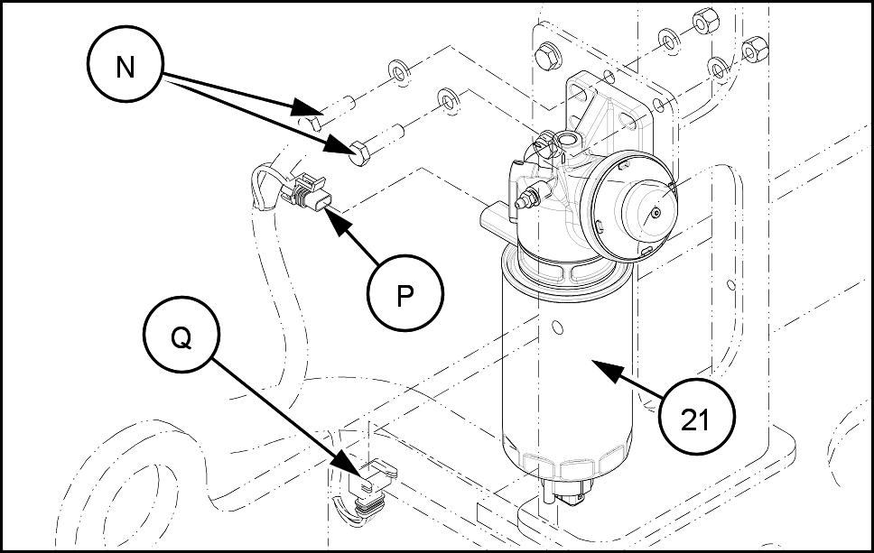
T ransfer fuel line fittings from the removed filter (M) new filter (21) . NOTE: NOT pre - fill the filter element, use ONL Y the hand pump fill and bleed the fuel system.
Install new fuel filter assembly (21) using the existing mounting hardware (N) .
Connect the fuel lines the new filter .
Connect the WIF harness connector (Q) the sensor the bottom the filter .
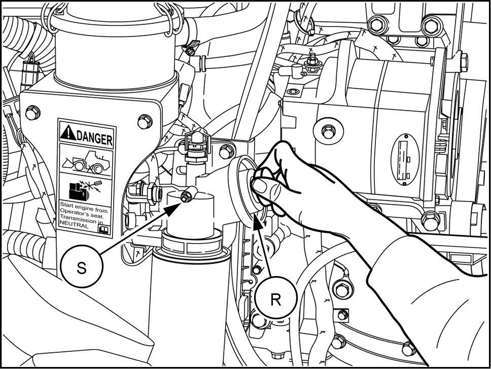
Connect the WSH harness connector (P) the heater the front the filter head. 10. To bleed air from the system, use the pump (R) the top the filter . Open the Fuel Filter bleeder (S) and pump until fuel flows without air bubbles. Close the bleeder .
RAIL12WEL0830AA 16
RCPH1 1WHL244AAH 17
Installing Engine Block Heater Kit Components
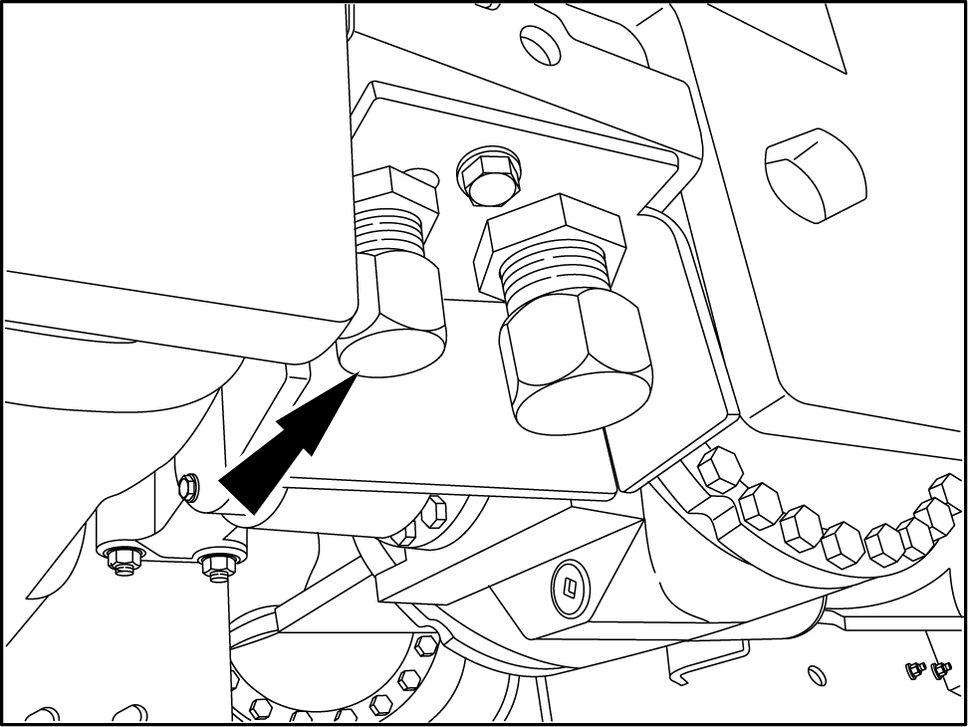
After the engine has cooled and the temperature the coolant has reached a safe level, remove the radiator cap.
With a suitable container the proper capacity under the drain, open the coolant drain cap turning counterclockwise and drain the coolant from the system. The coolant capacity is approximately 56.8 l ( 15.0 gal ). After all the coolant is drained, secure the coolant drain cap.
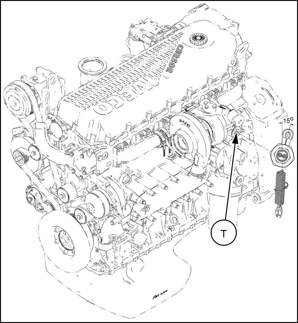
Clean the area surrounding the block heater mounting location. Remove the hole plug (T) from the block heater mounting hole the side the engine.
Preassemble the block heater (24) , gaskets (24A) and (24B) , and engine block plug (24C) and small nut (24D) shown. Apply LOCTITE® 592 PST the threads the engine block plug. NOTE: Gaskets (24A) and (24B) must installed the engine side the assembly for proper sealing.
RCPH1 1WHL225AAH 18
RAIL12WEL0829BA 19
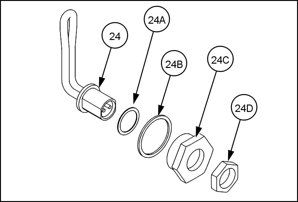
RCPH10FWD003GAG 20
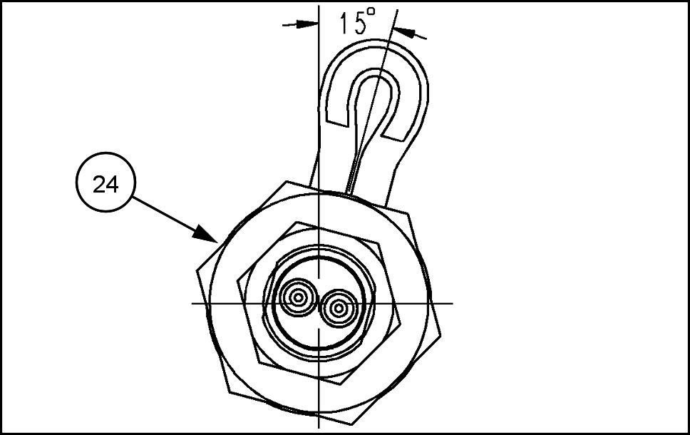
Install the block heater assembly (24) . Make sure that the heater element is ° from center in the vertical position and not contacting any internal surfaces.
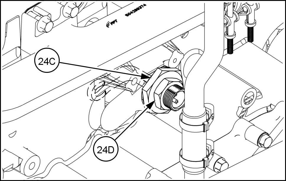
Tighten the engine block plug (24C) a torque 100 1 N·m ( 73.8 84.8 ). Tighten the small nut (24D) a torque - N·m ( 22.1 29.5 ).
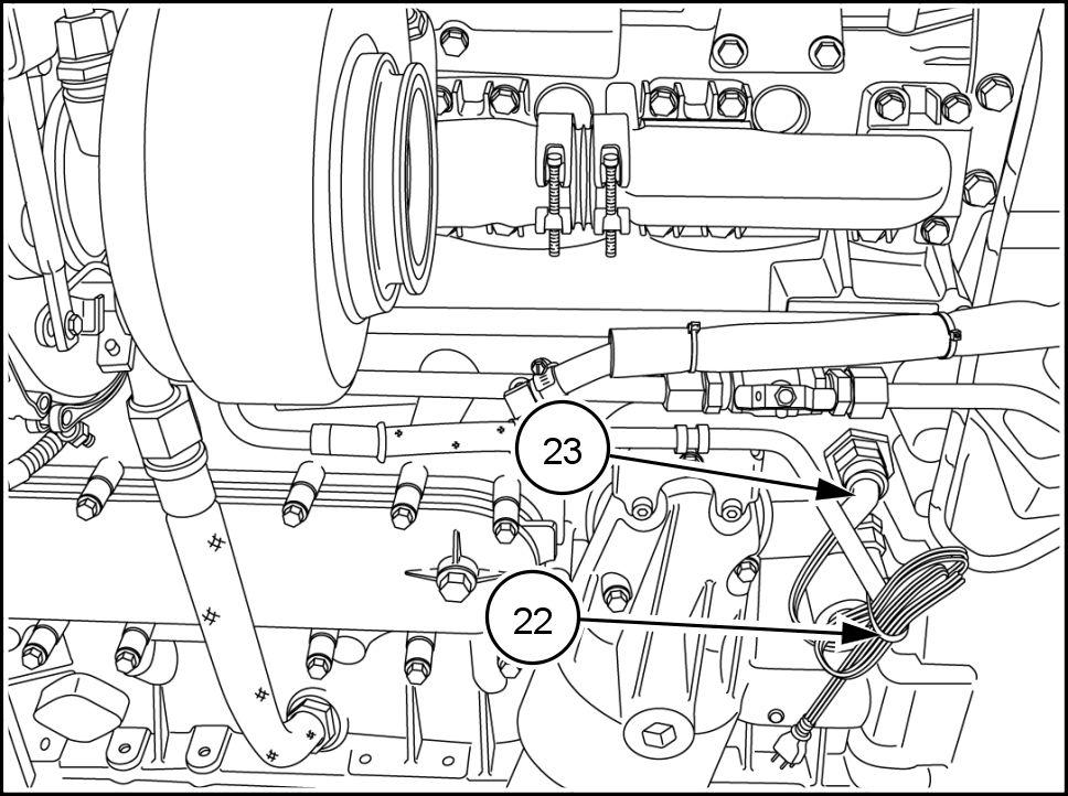
Plug in the engine heater cable (23) and secure with a tie strap (22) . Refill the engine coolant.
RAIL12WEL0831AA 21
RCPH10FWD772ABJ 22
RCPH1 1WHL044AAR 23
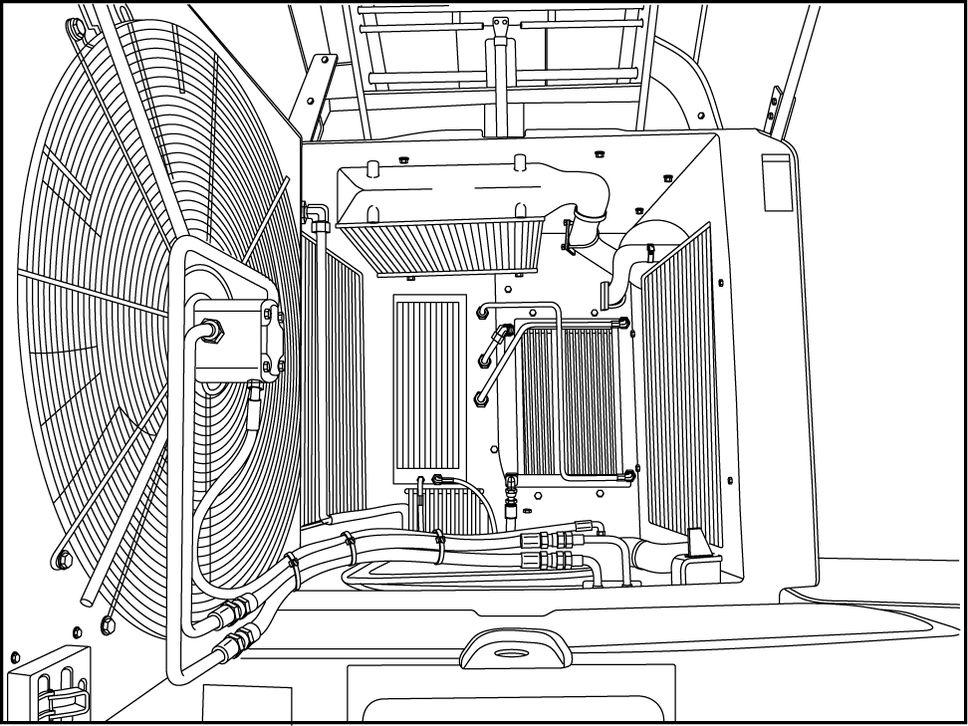
Installing Cab Heat Load V alve Kit Components
Open the rear access door .
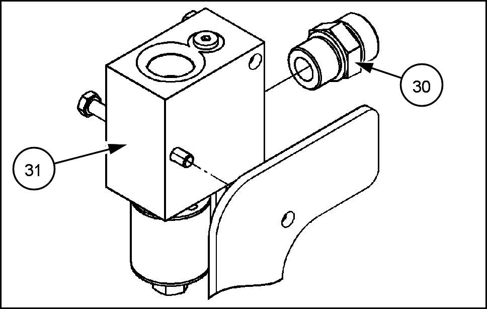
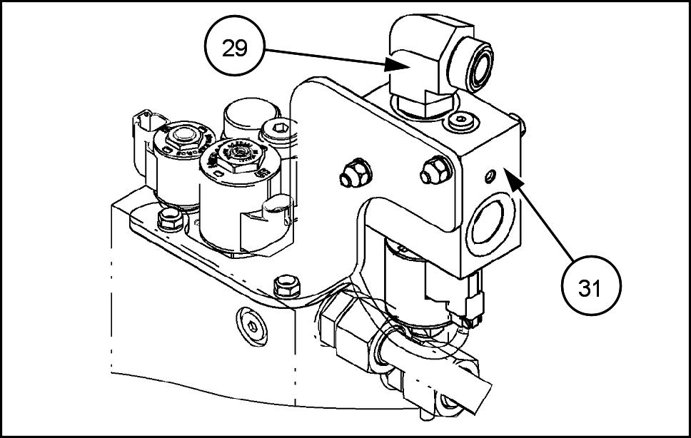
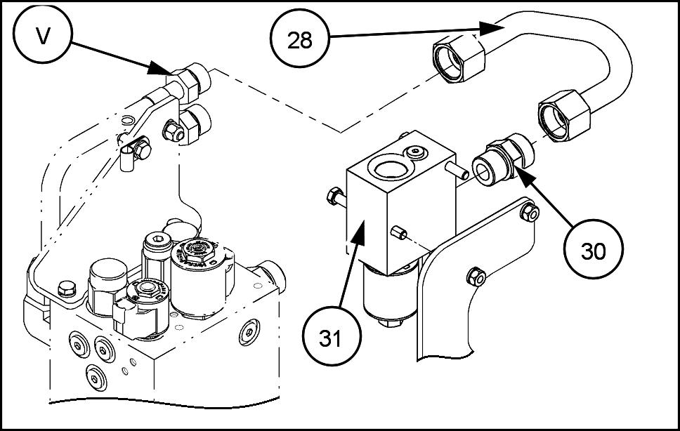
Install the connector (30) the port the cab heat load combination valve (31) .
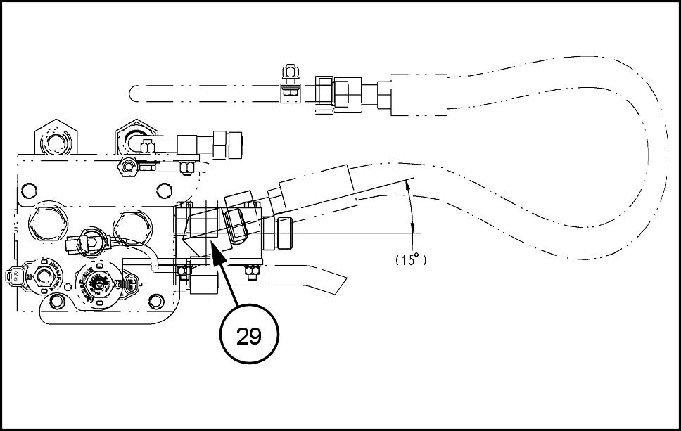
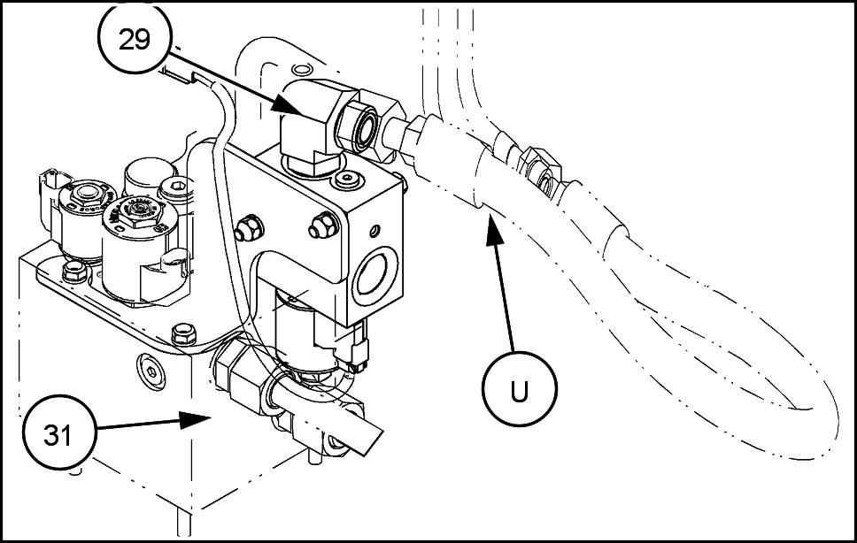
Install the elbow (29) the OUT port the cab heat load combination valve (31) .
Position the elbow (29) ° towards the rear for proper hose connection later .
RCPH1 1WHL124AAH 24
RAIL12WEL0913AA 25
RAIL12WEL0914AA 26
RAIL12WEL0915AA 27
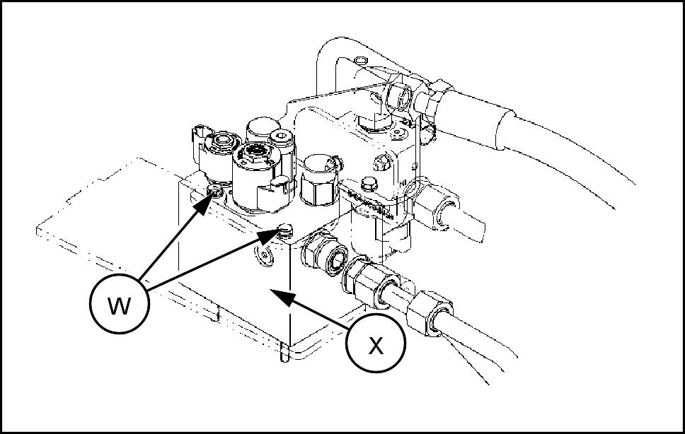
Remove the front two retaining bolts (W) from the reverser valve (X) . Save the hardware for reuse later .
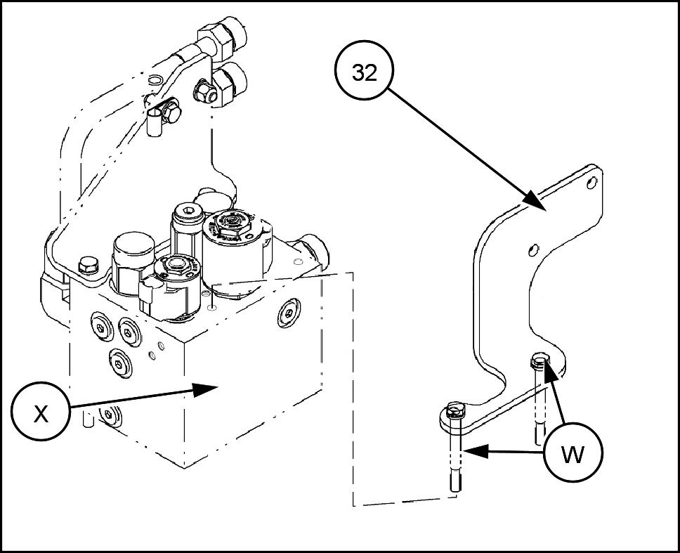
Assemble the support bracket (32) the fan reverser valve (X) with the existing two retaining bolts (W) .
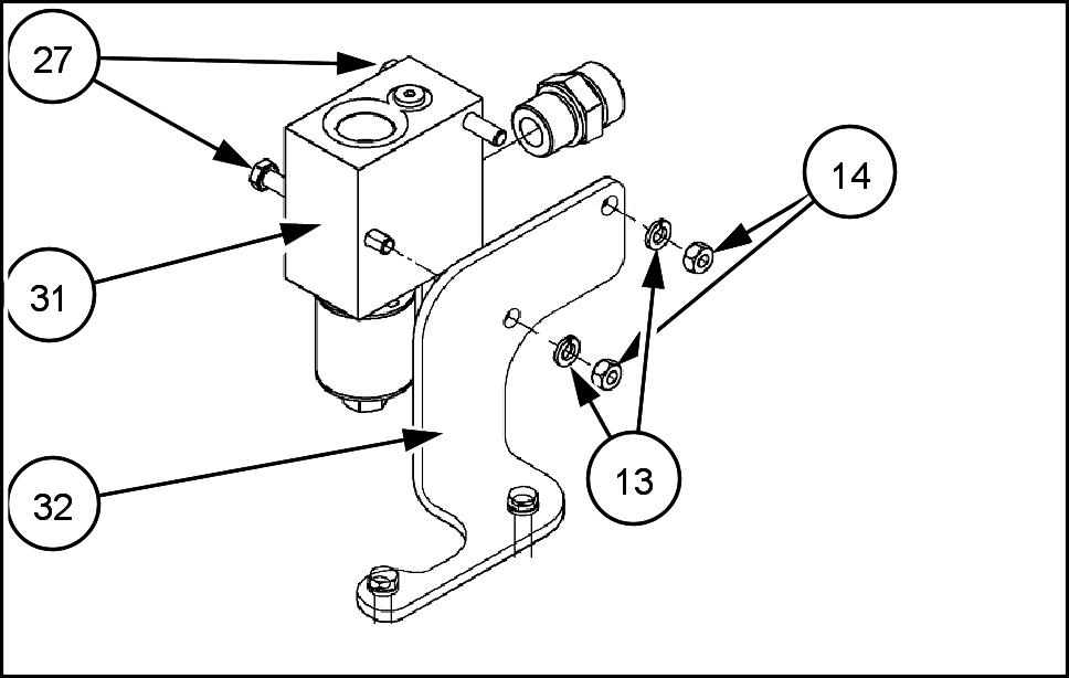
Secure the cab heat load combination valve (31) bracket (32) with two x bolts (27) , two lock washers (13) , and two nuts (14) .
RAIL12WEL0867AA 28
RAIL12WEL0916AA 29
RAIL12WEL0917AA 30
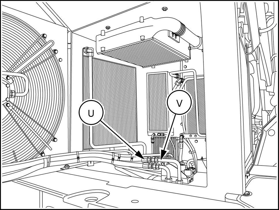
Connect a vacuum pump the hydraulic reservoir . T urn pump on. Disconnect top fan motor hose (U) from the reversing valve tube (V) .
10. Connect the cab heat load tube assembly (28) the fan reverser valve tube (V) and the connector (30) the port the cab heat load combination valve (31) .
1 Connect the fan motor hose (U) the elbow (29) the OUT port the cab heat load combination valve (31) . 12. T urn vacuum pump Remove the vacuum pump from the reservoir .
13. Open cab access door the right side the cab.
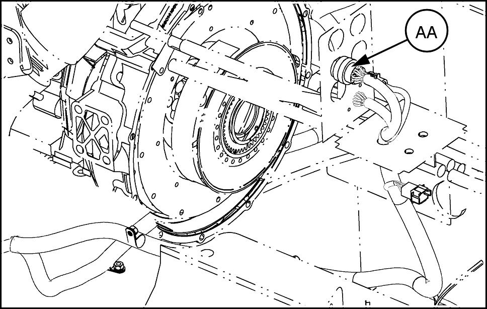
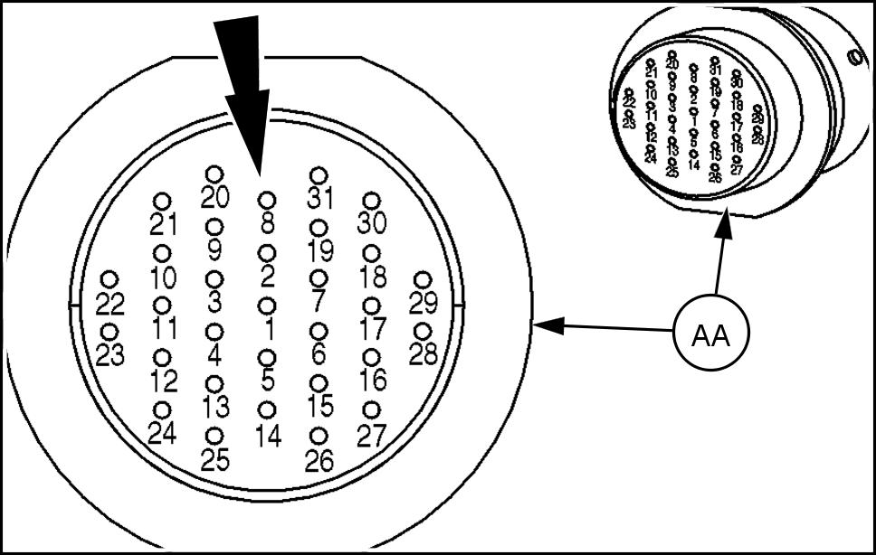
Disconnect the ENG connector (AA) .
RCPH1 1WHL006AAL 31
RAIL12WEL0918AA 32
RAIL12WEL0919AA 33
RAIL12WEL0922AA 34
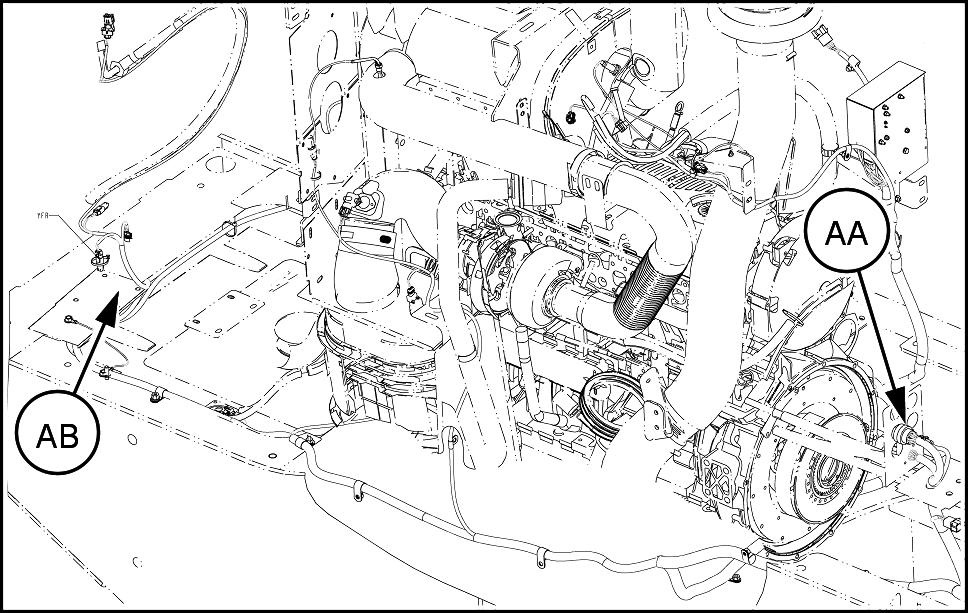
14. Loosely route the long cab heat jumper harness (25) from the ENG connector (AA) , along the routing the rear chassis harness the cab heat load combination valve (AB) area inside the rear chassis access door .
Position the single terminal the jumper harness near the ENG connector . Secure the jumper harness the existing rear chassis harness every 0.6 m (2 ) with cable tie straps (33) .
15. Remove the plug from terminal 8 location from the rear the ENG harness connector (AA) . Insert socket contact for wire 61H_B through the seal for terminal 8 location until it seats into the ENG connector . Lightly pull the wire assure that it is seated.
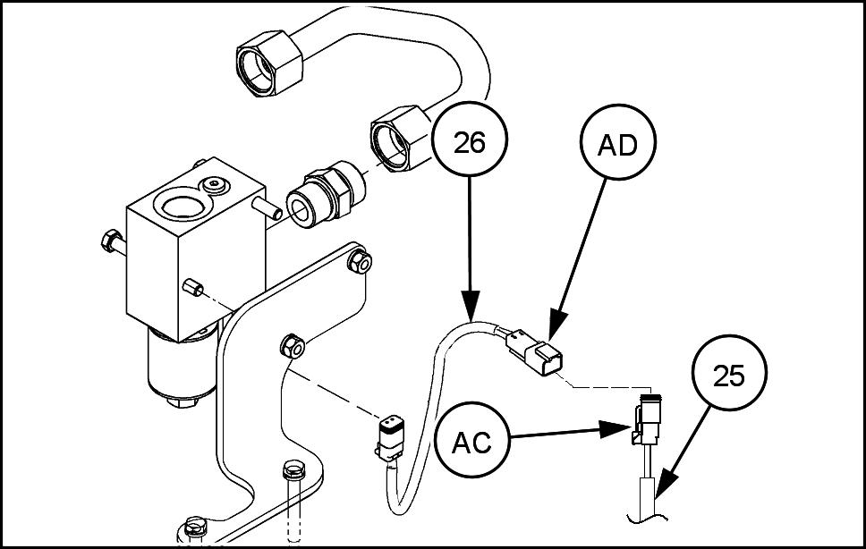
16. Secure the ring terminal the jumper harness the ground stud above the ENG connector inside the right cab access door . 17. Inside the rear access door , connect the YL V3 connector (AC) the jumper harness (25) the YL V3 connector (AD) the cab heat solenoid jumper (26) .
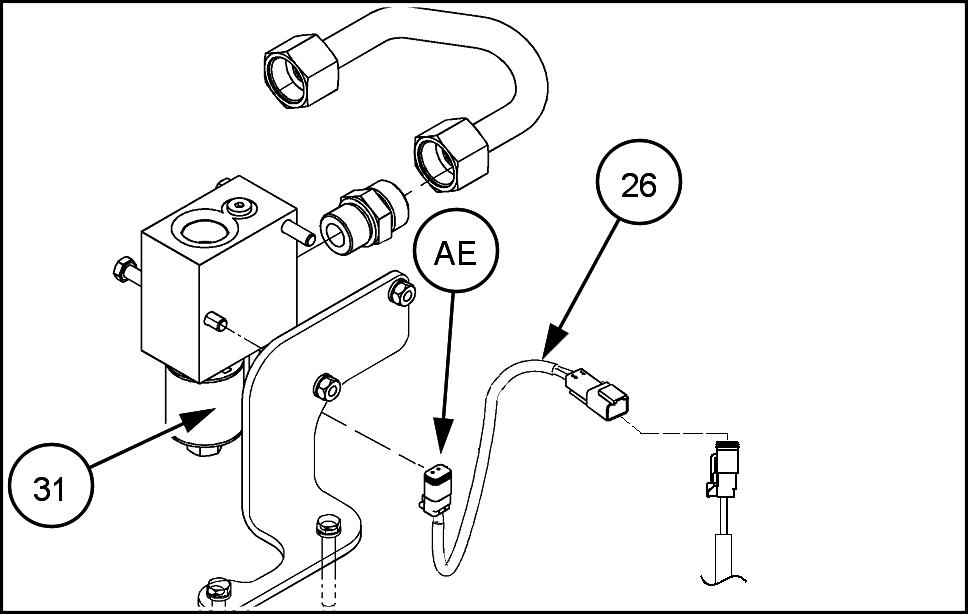
18. Connect harness connector YL V2 (AE) from the cab heat jumper (26) the cab heat load combination valve solenoid (31) .
RAIL12WEL0920AA 35
291661A1 36
RAIL12WEL0921AA 37
RAIL12WEL0921AA 38
V alidating Kit Upgrade
Check the level the hydraulic reservoir . Add oil necessary . See appropriate Operator's Manual for specifications. T urn battery disconnect position. Close access door . Start engine. Run low idle. Allow the engine idle for a few minutes before checking for leaks. Adjust coolant level needed. Inspect for fuel leakage. leak is detected, repair necessary . Inspect for oil leakage. leak is detected, repair necessary . Ensure hydraulic reservoir oil level is correct. Install access covers and plates.