9 minute read
1012 Modules / sensors


1012 Modules / sensors
CLAAS AUTO CONTOUR (CAC)
Removing left height sensor
280441-001
280442-001 170991-002
The SWATH UP CAC feature works in conjunction with the CAC option available on certain combine models. A sensor is installed at each end of the SWATH UP. These sensors send a signal to the combine to allow it to maintain a consistent cutting height as the header follows ground contours. The SWATH UP is factory-equipped for CAC. However, before using the CAC feature, you must: ► Ensure that the CAC sensors’ output voltage range is appropriate for the combine. ► Calibrate the CAC system so that the combine can correctly interpret data from the height sensors on the header. ► Once calibration is complete, you are ready to use the CAC feature in the field. For each combine, certain operation settings can be used to improve the performance of the CAC feature.
170985-004
► Lower header to ground, shut down engine, and remove key from ignition.
168333-005
DANGER
To avoid bodily injury or death from unexpected startup of machine, always stop engine and remove key from ignition before leaving operator’s seat for any reason.
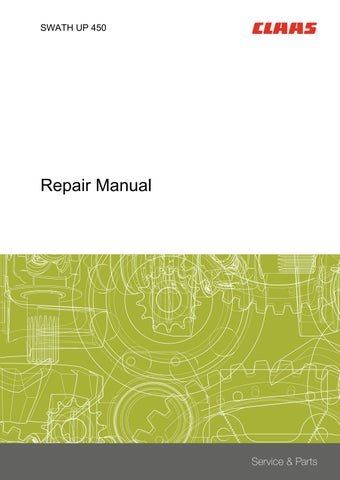
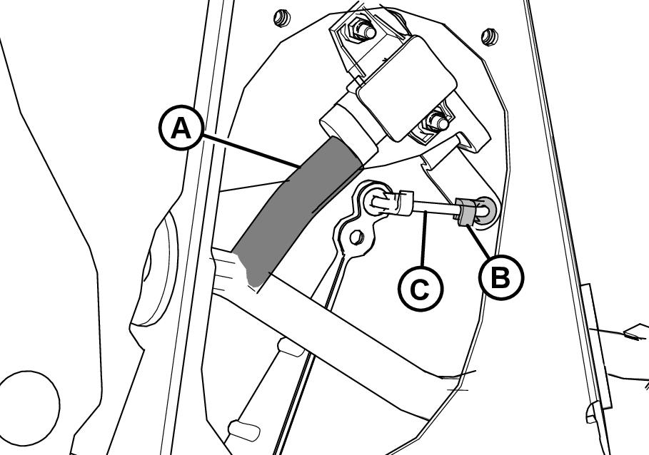
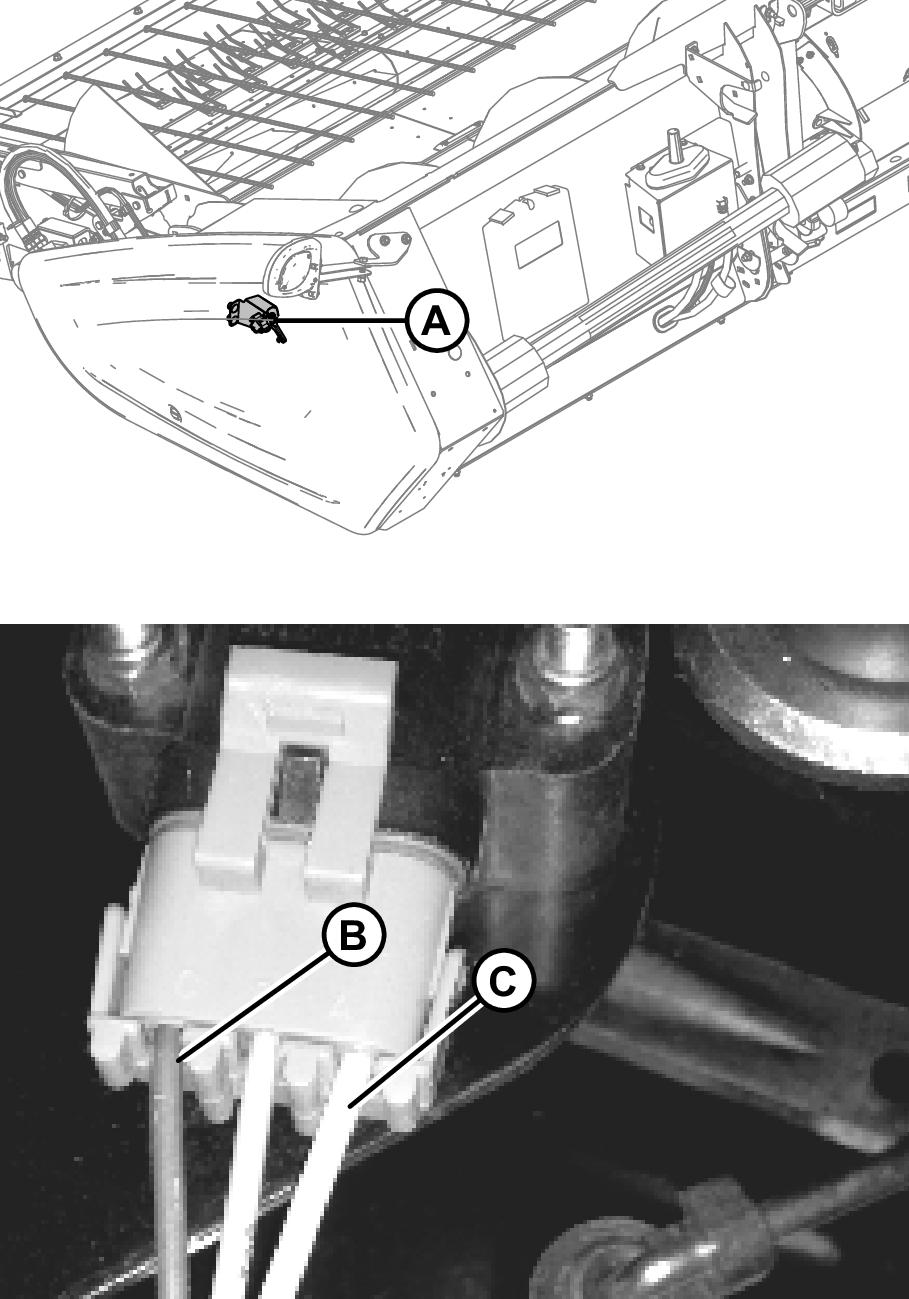
► Open left endshield. Page 158 ► Disconnect the wire harness (A). ► Push up on the rod end clip (B). Slide the linkage rod (C) out of rod end clip (B).
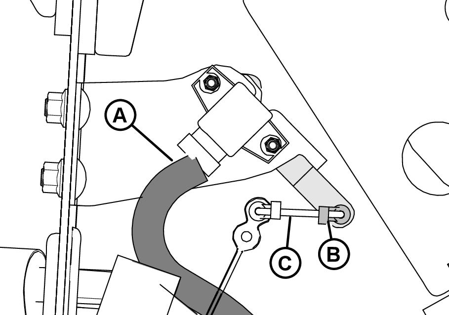
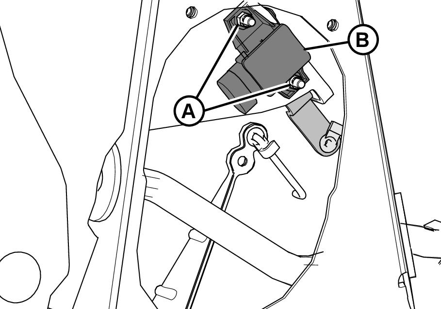
► Remove nuts and bolts (A). ► Remove sensor (B) complete with control arm.
61
62
Installing left height sensor
280442-001
280441-001 ► Lower header to ground, shut down engine, and remove key from ignition.
168333-005
DANGER
To avoid bodily injury or death from unexpected startup of machine, always stop engine and remove key from ignition before leaving operator’s seat for any reason.
► Open left endshield. Page 158
► Install sensor (B) complete with control arm.
Center the bolts in the slots and secure with nuts (A).
► Slide the linkage rod (C) into the rod end clip (B).
Secure the rod end clip by pressing it onto the linkage rod (C). ► Connect the wire harness (A). ► Close left endshield. Page 159
63
64
Removing right height sensor
280446-001
280449-001
280450-001
65
► Raise the hold-down and engage lift cylinder safety props. ► Lower header to ground, shut down engine, and remove key from ignition.
168333-005
DANGER
To avoid bodily injury or death from unexpected startup of machine, always stop engine and remove key from ignition before leaving operator’s seat for any reason.
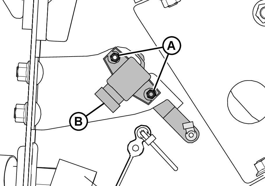
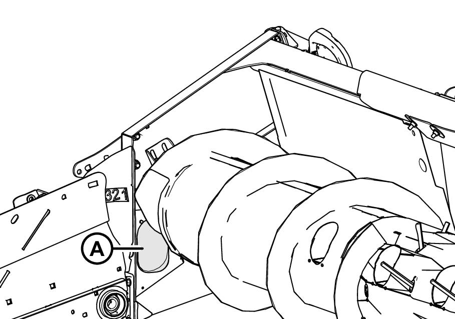
► Locate the access panel on the inside of the right end frame. Remove the 2 bolts (A) from access panel (B). ► Remove access panel (B).
► Disconnect the wire harness (A). ► Push up on the rod end clip (B). Slid the linkage rod (C) out of rod end clip (B).
► Remove nuts and bolts (A). ► Remove sensor (B) complete with control arm.
66
67
280447-002
280448-001
Installing right height sensor
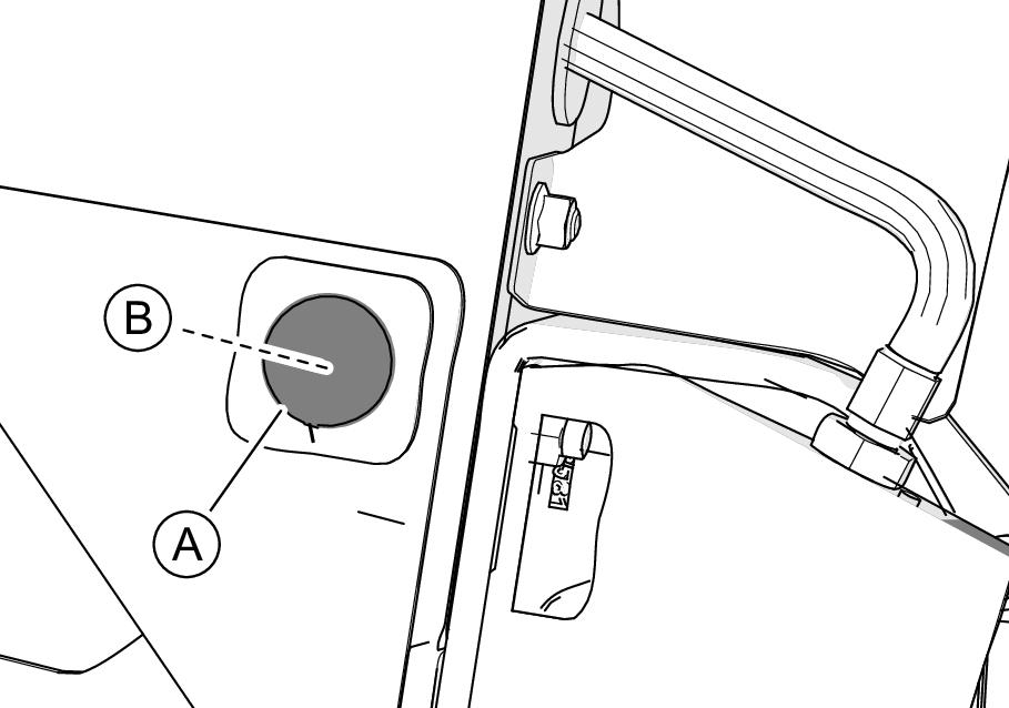
280448-001 1212-003 ► Locate plug (A) on outboard side of the endsheet and remove plug (A) to gain access to nut (B) securing the long control arm to the frame. ► Remove nut (B).
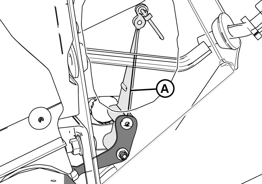
► Remove the long control arm (A) complete with linkage rod, rod end clip and activator arm.
68
69
170988-004
► Lower header to ground, shut down engine, and remove key from ignition.
168333-005
DANGER
To avoid bodily injury or death from unexpected startup of machine, always stop engine and remove key from ignition before leaving operator’s seat for any reason.
► Install the long control arm (A) complete with linkage rod, rod end clip and activator arm.
70
280447-002
280450-001
A
C B
► Install nut (B). ► Install the hole plug (A).
► Install sensor (B) complete with control arm. ► Secure with nuts and bolts (A). Center the bolts in the slots and secure with nuts (A).
► Slide the linkage rod (C) into the rod end clip (B).
Secure the rod end clip by pressing it onto the linkage rod (C). ► Connect the wire harness (A).
► Install the access panel (B), secure it with bolts (A).
71
72
280511-001
280446-001
73
74
Height sensor output voltage range – combine requirements
The height sensor output must be within a specific voltage range for the combine or the AUTO CONTOUR feature will not work properly.
Description
Low voltage limit High voltage limit Range (difference between high and low limits) 0.7
4.3
2.5 V
V
V
Manually checking voltage range
178672-004
You can manually check the output voltage range of the AUTO CONTOUR sensor at the float indicator box.
To manually check the sensor’s output voltage range, follow these steps: ► Position header until header wheels are approximately 150 mm (6 in.) above the ground.
Ensure the float spring is fully extended. If float spring is not fully extended during the next step, voltage may go out of range during operation causing a malfunction of the AUTO CONTOUR system. ► Shut down the combine. Position key so that power is supplied to sensors. ► Open left endshield. Page 158
289349-001
313784-001
280446-001 ► Locate left height sensor (A). ► With connector plugged into sensor, measure voltage between gray signal wire (B) on one side of the connector and brown ground wire (C) on other side.
This is the maximum voltage for the left sensor.
► Locate access panel (A) on inside of right end frame.
► Remove the 2 bolts (A) from access panel (B). ► Remove access panel (B).
75
76
77
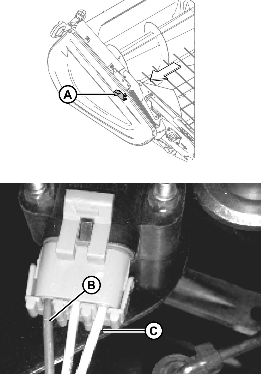
289351-001 ► Locate the right height sensor (A). ► With connector plugged into sensor, measure voltage between orange signal wire (B) on one side of connector and brown ground wire (C) on other side.
This is the maximum voltage for the right sensor. ► Start combine and fully lower the combine feeder house.
The float spring should be fully compressed. ► Shut down the combine. Position key so that power is supplied to sensors. ► Repeat the voltage measurements for both sensors.
These are the minimum voltages.
► Compare voltage measurements to specified values. Page 56 ► If the sensor voltage is outside the low and high limits, or if the voltage range is less than the specified value, adjustments are required. Page 58 Page 59
78
170994-003
B
► Lower header to the ground, shut down combine, and remove key from ignition.
168333-005
A
D C E DANGER
To avoid bodily injury or death from unexpected startup of machine, always stop engine and remove key from ignition before leaving operator’s seat for any reason.
► Open the left endshield. ► Loosen nuts (A). ► Rotate control (B) until desired voltage range is achieved. Page 56
280532-001
79
1212-003
If the voltage range is too large or too small, you may need to relocate the linkage rod (C) to a different hole in sensor control arm (D). If that does not work, relocate the linkage rod (C) to a different hole in sensor control arm (E). ► Close left endshield. Page 159
181114-002
313784-001 168333-005
DANGER
To avoid bodily injury or death from unexpected startup of machine, always stop engine and remove key from ignition before leaving operator’s seat for any reason.
► Raise the hold-down and engage lift cylinder safety props. ► Lower header to the ground, shut down combine, and remove key from ignition. ► Locate the access panel (A) on the inside of the right end frame.
► Remove the 2 bolts (A) from access panel (B). ► Remove access panel (B).
► Loosen nuts (A). ► Rotate sensor (B) until desired voltage range is achieved. Page 56
If the voltage range is too large or too small, you may need to relocate the linkage rod (C) to a different hole in sensor control arm (D). If that does not work, relocate the linkage rod (C) to a different hole in sensor control arm (E).
80
280446-001
B A
E
C
D 81
280540-002
82
280446-001
Field operation settings
A C
B
A
C
256012-001
B
256013-001 1212-003 ► Once complete, install the access panel (B) and secure it with bolts (A).
83
170999-001
84
85
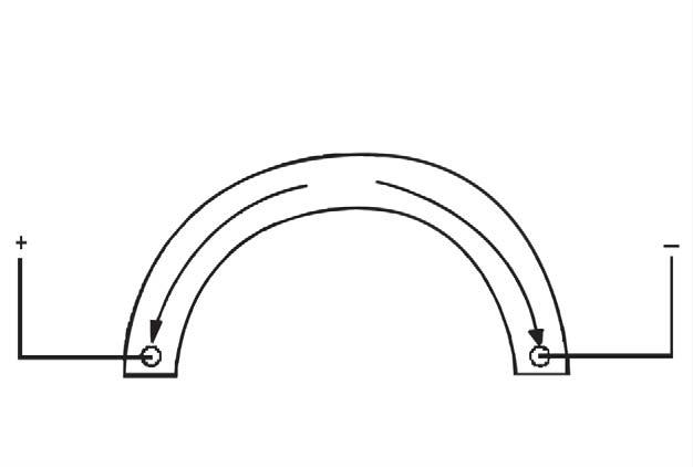
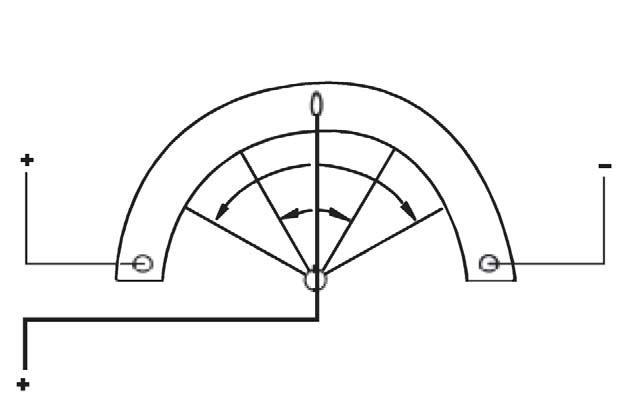
The position sensor supplied with the Auto Header Height is 1000 ohm (1 k) industrial series sensors containing sealed connectors. Normal operating signal voltages for the sensors fall between 10% (0.5VDC) and 90%(4.5VDC). Below 5%, a sensor is considered to be shorted; above 95%, open. An increase in sensor voltage correlates to an increase in header height. Each sensor is constructed with a power wire and a ground wire. Inside the sensor, these two wires are connected by a high resistance filament band (C). The resistance measured across the power (A) and ground (B) wires, should read a constant value between 800 and 1200 ohms (0.8-1.2 k) with the nominal reading being 1000 ohms (1 k).
In addition to the power (A) and ground (B) wires, a signal wire (C) is connected internally to a movable wiper that sweeps the high resistance filament band. This wiper is attached to an external arm. As the external arm is rotated and the wiper is moved toward or further away from the power wire connection, the measure of resistance at the signal wire (C) changes. The resistance measured across the signal and ground wires should show a uniform progressive increase from a low (80–100 ohms) to a high (800–1200 ohms). This can be observed if an ohmmeter is connected across the signal and power wires and the sensor shaft rotated. When an input voltage is applied to the high resistance filament band through the power wire (A) the output (or “measured”) voltage in the signal wire (C) is changed by this variable resistance.