1 minute read
Steering hydraulics pump
Reverse front attachment LEXION 580 - 510 up to serial no. 586 00336, 585 00162, 584 00895, 583 00298
Hydraulic cylinder
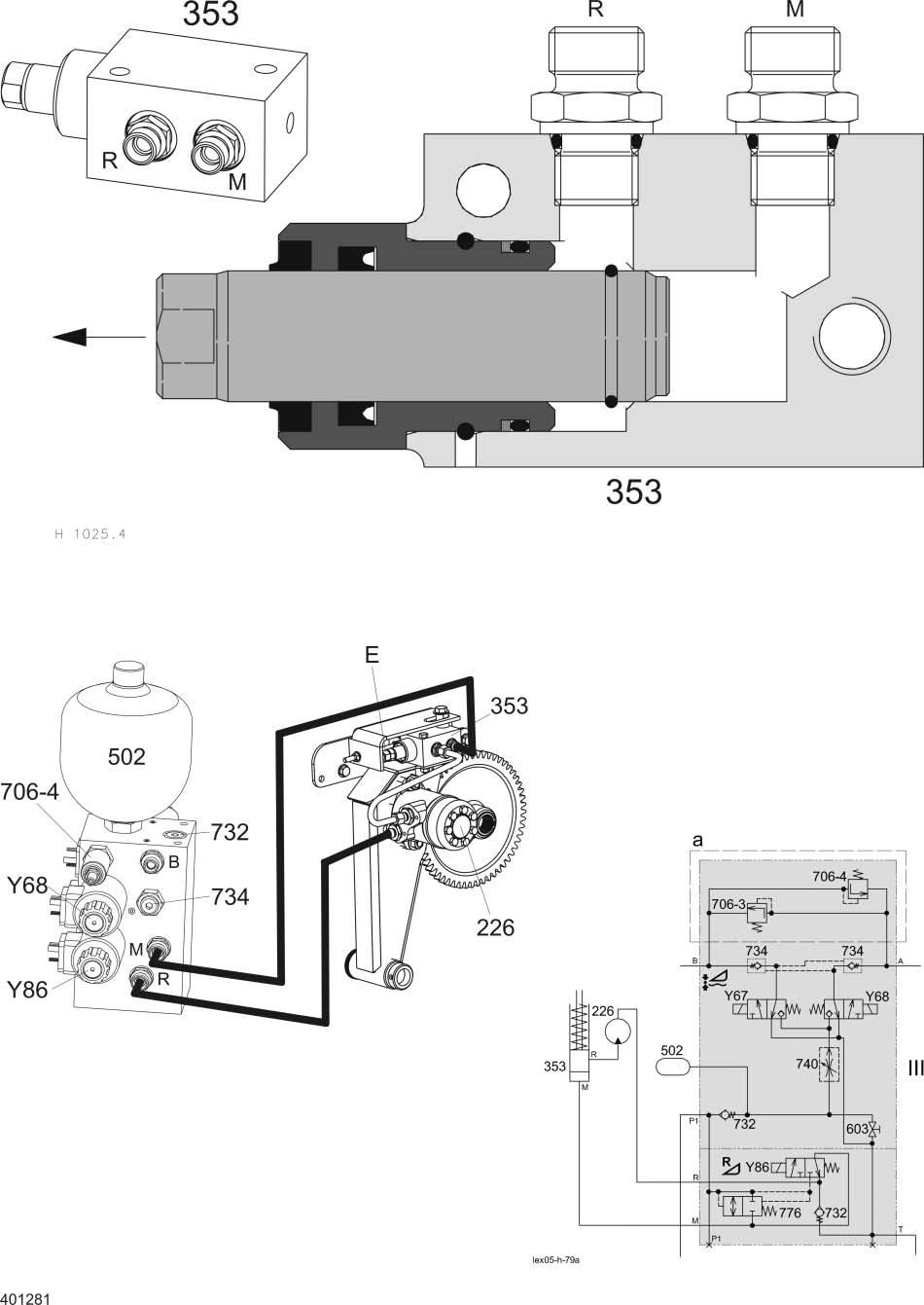
Key to diagram:
226 Front attachment reverser drive motor .......................OMP 200 353 Reverse front attachment hydraulic cylinder 502 AUTOCONTOUR / Cross levelling accumulator 706-3* Cross levelling pressure relief valve (Montana)..........200 bar 706-4* Cross levelling pressure relief valve (Montana)..........200 bar 732 Non-return valve 734 Lock-up valve unit (non-return valve) 776 Reversing connecting valve (with restrictor)
Y68 AUTOCONTOUR cross levelling right solenoid valve Y86 Reverse front attachment solenoid valve
III AUTOCONTOUR / Reverse valve block
a Option E Setscrew T Tank port P Pump via master valve port M Front attachment reverse hydraulic cylinder port R Motor return line port
Description of function:
Reversing When the solenoid valve (Y86) is actuated, the reversing cylinder (353) extends and swings the hydraulic motor (226) to the drive gearwheel. Just before reaching its end position, the oil flow from the reversing cylinder (353) to the hydraulic motor (226) is released, ensuring reliable gearwheel engaging.
The non-return valve (732) keeps the hydraulic motor (226) from starting when pressure peaks occur in the return line.
Adjustment The reverser support is aligned towards the feed rake conveyor drive shaft by adjusting an eccentric bushing on the reverser cylinder (353). The piston stroke is adjusted using the set screw (E). With the reverser swung in, the set screw (E) must have a play of 0.5 mm from the end stop, then jam the set screw (E).
Installation position of reverser motor OMP 200
3.13.2
Reverse Front Attachment (without AUTO-CONTOUR)
LEXION 580 - 510


