3 minute read
Radial spreader disc drive pump
Key to diagram:
115 Grain tank unloading lubricant reservoir 213 Reel drive pump ......................................................15 cm3/rev. 312 Threshing mechanism coupling hydraulic cylinder 321 Grain tank unloading hydraulic cylinder 232 Grain tank unloading lubricant pump 347 Straw chopper clutch hydraulic cylinder 3003 Service brake / Parking brake hydraulic cylinder 3003-1 Service brake / Parking brake right hydraulic cylinder 3003-2 Service brake / Parking brake left hydraulic cylinder 407 Orifice plate G..............................................................ÿ 1 mm 731 Non-return valve 760 One-way restrictor, one-sided
Y21 Threshing mechanism clutch engage solenoid valve Y35 Grain tank unloading solenoid valve Y76 Straw chopper clutch solenoid valve Y88 Front attachment clutch solenoid valve (proportional) Y105 Differential lock solenoid valve Y106 Parking brake solenoid valve Y107 Gearbox shift 1st gear solenoid valve Y108 Gearbox shift 2nd gear solenoid valve
T Tank port P5 Ground drive feed pump port A Hydraulic cylinder port S Emergency operation screw
VI Low-pressure hydraulics valve block XII Electrohydraulic gearshift (EHS) ñ 2-gear manual gearbox
Description of function:
Parking brake The parking brake system consists of a spring-type accumulator in the brake cylinders. The low-pressure circuit of the machine is used for releasing the parking brake.
With solenoid valve (Y106) de-energised, the connection is provided from the hydraulic cylinder (A) to the return line into the tank (T) via the conical seat in the valve insert (V). Here the low pressure (P5) applied is blocked by the spherical seat in the valve insert. When the corresponding solenoid valve (Y106) is actuated, the plunger opens the ball in the valve insert and closes the return line (T) with the conical seat. The low pressure (P5) is thus applied to the hydraulic cylinder (3003 and/or 3003-1 / 3003-2) via the consumer port (A) whereas the return line to the tank (T) is blocked.
- Wheeled machine Drum brake principle (dry)
- TerraTrac (half-tracks) Multi-disc brake principle (wet)
Note: In case of emergency operation, screw (S) must be slightly screwed in up to the stop (otherwise the valve seat will be damaged) to make the conical seat in the valve insert (V) close the return line to the tank (T) tightly.
4.1.6 Hydraulic Cylinder of Low-pressure Hydraulic System
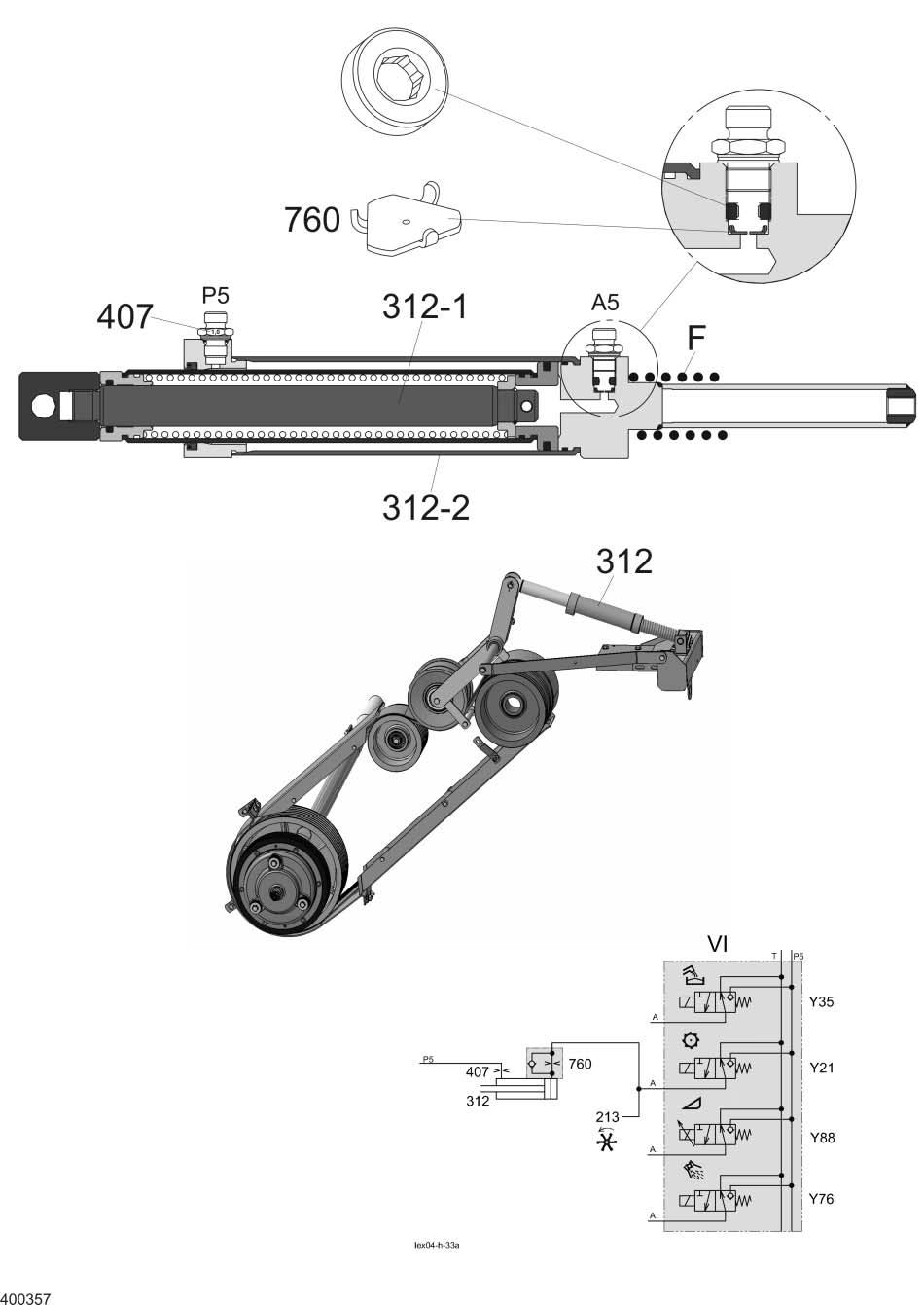
Threshing mechanism clutch engage (step cylinder)
Key to diagram:
213 Reel drive pump..........................................................15 cm3/rev. 312-1Threshing mechanism clutch hydraulic cylinder 1st stage 312-2Threshing mechanism clutch hydraulic cylinder 2nd stage 407 Orifice plate G 760 One-way restrictor, one-sided
Y21 Threshing mechanism clutch engage solenoid valve Y35 Grain tank unloading solenoid valve Y76 Straw chopper coupling solenoid valve Y88 Front attachment clutch solenoid valve
A5 Threshing mechanism clutch engage port (step cylinder) F Spring P5 Low-pressure port
VI Low-pressure hydraulics valve block
Description of function:
The threshing mechanism clutch hydraulic cylinder (312) allows smooth engaging of the threshing mechanism, matched to the machine.
General low-pressure hydraulic system rules: With the engine running, a pressure of (19+4 bar) always acts on the hydraulic cylinders via port (P5). This ensures that the corresponding drive belt is relieved when functions are "not actuated".
Engaging the threshing mechanism clutch
Disengaging the threshing mechanism clutch The threshing mechanism clutch engage solenoid valve (Y21) is actuated. The applied low pressure is transmitted into the step cylinder (312) via port (A5). At first the first step (312-1) of the step cylinder extends and pre-stresses the drive belt = smooth engaging of threshing mechanism, then the second step (312-2) of the step cylinder extends and ensures the positive engagement of the drive belt. Stage 1 retracts.
When disengaging, the 2nd step (312-2) of the step cylinder is retracted by the applied low pressure at port (P5).
Note: The hydraulic cylinder (312), the one-way restrictor valve (760) in port A5 and the orifice plate (407) in port P5 are individually matched to the machine and are therefore different, depending on the machine type!
Hydraulic Cylinder of Low-pressure Hydraulic System
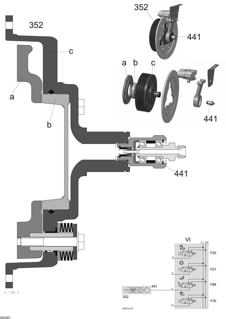
Front attachment clutch with rotary coupling


