1 minute read
1b Main power supply

from Claas Balers ROLLANT 240 250 ROLLANT 250 with UNIWRAP Electric System Technical Systems Manual - PDF

1b
Main power supply
Rollant 250 Comfort
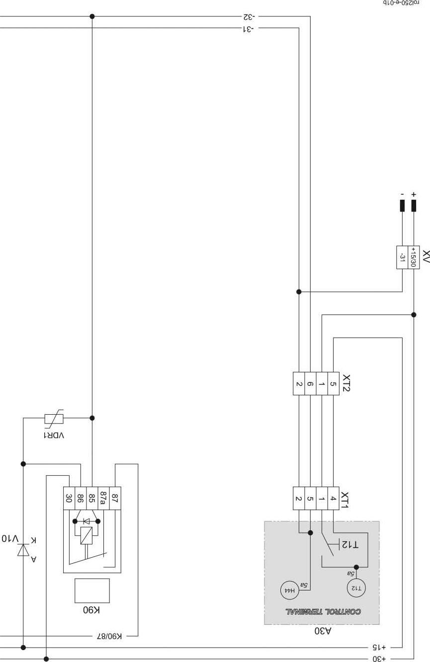
01b - Main power supply Rollant 250 Comfort
Key to diagram: A30 CCT terminal .....................................Wiring loom B-part 1 H44 Buzzer................................................Wiring loom B-part 1 K90 Power supply relay (protected against reverse polarity)....Wiring loom B-part 2 T12 Main switch.........................................Wiring loom B-part 1 V10 Reverse polarity protection diode.......Wiring loom B-part 2 VDR1 Varistor...............................................Wiring loom B-part 2 XT1 Terminal connector ............................Wiring loom B-part 1 XT2 Terminal connector ............................Wiring loom B-part 1 XV Power supply connector ....................Wiring loom B-part 1
Measured value table: Item Component Measured value Note K90 Remote control relay 20 A 30 A 75±10 Ω (Pin 86/1 ñ 85/2) (Pin 87a/4 ñ 30/3) (Pin 87/5 ñ 30/3)
Description of function:
Main power supply Power supply from the tractor to the baler is via connector XV. On the tractor, this prower supply should be protected by a fuse of 25 A max.
Potential + 15 This is switched by the main switch T 12 on terminal A30 (electronics +).
Potential K 90 / 87 Potential K 90/ 87 is a power plus protected against reverse polarity by diode V10.
Overvoltage protection VDR1 becomes conducting when overvoltage occurs. This smooths the voltage peaks in the electronics circuit (+15 / -32).
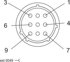
Connector pin definition
Socket K90 Connector XV
Connector XT1 Socket XT1
Connector XT2 Socket XT2


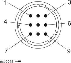


Connector mm Colour K90/30 2.5 bk K90/85 1.0 br-rd K90/86 0.75 bk-rd K90/87 2.5 bk-wt
XT1 ñ 1 1.5 bk XT1 ñ 2 1.5 br XT1 ñ 4 1.5 bk-rd XT1 ñ 5 1.5 br-rd
XT2 ñ 1 1.5 bk XT2 ñ 2 1.5 br XT2 ñ 5 1.5 bk-rd XT2 ñ 6 1.5 br-rd Connector mm Colour XV - 15/30 2.5 bk
XV - 31 2.5 br