2 minute read
SECTIONAL VIEW.......................................................................................................................................................C4
Differential
Advertisement
Disassembly of the differential lock
Note: The hydraulic differential lock assembly can be serviced by removing only the left axle tube.
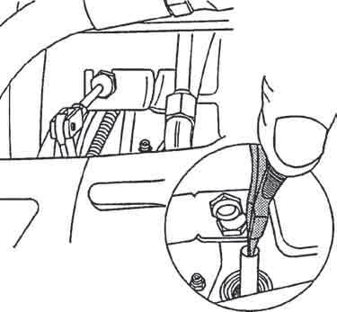
– Remove the left-hand axle tube. – Remove the coupling (17) and take out the hose (18).
Note: If access to the fitting (17) is difficult, remove the command (A).
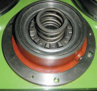
– Loosen the screws (14) alternately in order to slowly release the spring (6). – Remove the flange (13), the friction washer (8), the sliding dog (7) and the spring (6). – Extract the cup (4) and the deflector (5).
Note: Identify the installation direction of the deflector (5).
– Remove the circlip (9). – Remove the piston (11) using a jet of compressed air. – Remove the O-rings (10), (12) (19) and (13) located inside the flange. – Loosen screw (15), (if required).
Reassembly of the differential lock

– Clean the finger (15) and coat it with Loctite(243) then fit it and tighten it on the flange (13). – Coat the O-rings (10), (12) with miscible grease, to properly position them in the bottom of their respective grooves.
Recommendation: Mark the piston in relation to the finger (15) for ease of assembly.
– Enter the piston (11) in the flange (13) (Fig. 4) observing the finger location (15).
A
341msm41
18
5 7
341msm42
13
5 13 4
14
10
8 7
11
12
15 9 6 20
17
Fig. 2
6
4 19
Fig. 3
Differential
– Fit the circlip (9), the deflector (5) observing its installation direction, the cup (4). – Fit the O-ring (19), (Fig. 5). – Screw two opposite guide studs on the casing. – Install the spring (6), the sliding dog (7), the friction washer (8) and the flange (13).
Note: Orientate the inlet port of the differential lock of the flange upward.
– Fit and tighten 2 screws (14) to 8,5 to 13 daN.m. Remove the locating studs. Fit and torque tighten the two other screws to the same torque. – Fit the differential lock hose (18) and union (17).
Differential lock leak test
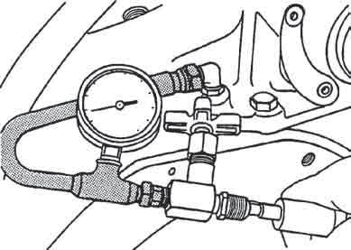
– When intervening on the piston (11), the seals (10) and (12), the flange (13), it is necessary to check the sealing of the assembly. – Fit a pressure gauge and a pressure-release valve n° 6005005310 on the supply union (17), (Fig. 6). – Supply the circuit with about 5-bar compressed air to check the proper displacement of the piston. – Reduce the pressure to 0,3 bar to perform the sealing test. – Close the valve. For 1 minute, no pressure reduction should be noticed on the pressure gauge. – Disassemble the pressure gauge and connect the supply tube (Fig. 6). – If it is disassembled: Connect the PTO command and perform the adjustment. – Refit the left-hand axle tube. – Check the operation of the differential lock.
5 13 4
14
10
8 7
11
12
15
343msm52
9 6
Fig. 5
17

343msm0l Fig. 6


