1 minute read
REFITTING THE LINERS..............................................................................................................................................A3


Cylinder head and valves
Inner diameter of the rocker..............20,065 - 20,115 mm Wear limit..........................................................20,16 mm
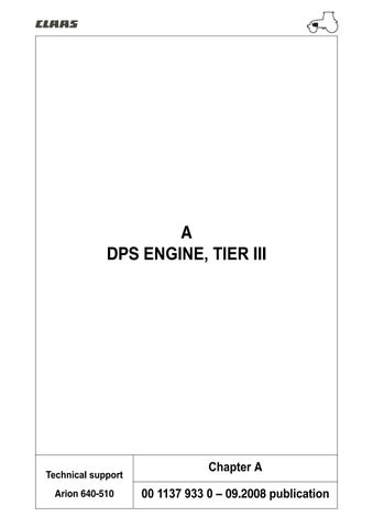
Inspecting the rockers
– Remove and clean the rockers (A). Mark them for refitting.
134hsm10 Fig. 6
A
– Measure the outer diameter of the rockers. If it is below the value recommended, change it. Specified value: Rocker outer diameter ..........................31,61 - 31,64 mm – Measure rocker clearance in the bore. Specified value: Bore diameter (in the block) .........................................31,70 - 31,75 mm Rocker and borehole clearance................0,06 - 0,13 mm – Check the head on the rocker journals. If it is flat or concave, change the rocker and check the camshaft lobes.
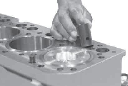
134hsm11 Fig. 7
Cylinder head and valves
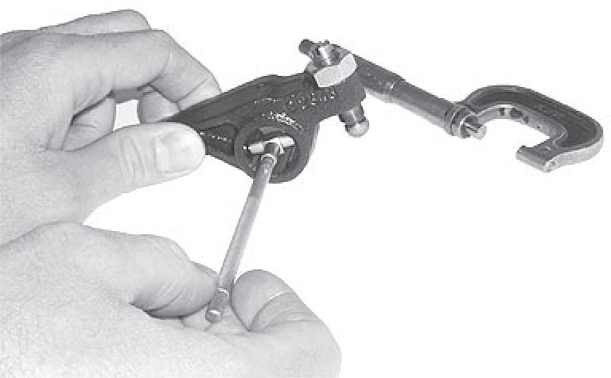
Measuring valve shrinkage
Measurements must be made at a maximum distance of 3 mm from the edge of the valve head. – Compare the measurements (A) between the 2 inlet and exhaust valves. Check that the gap does not exceed the value specified.
Note: If a cylinder has uneven valve wear, check the gap of boreholes on valve bridges.
Specified value: • Intake valve Shrinkage in the cylinder head .................0,77 - 1,27 mm Wear limit............................................................1,77 mm • Exhaust valve Shrinkage in the cylinder head .................0,81 - 1,31 mm Wear limit............................................................1,81 mm Maximum gap for a pair of valves per cylinder........................ .........................................0,3 mm
A
131hsm33 Fig. 9
Cylinder head flatness
– Check cylinder head flatness using a precision rule and a set of shims. Check along the length, across and in diagonal in several locations. Specified value: Maximum acceptable straightness error over the entire length or width ....................................................0,08 mm Maximum acceptable straightness error over the entire length of 150 mm ................................................0,03 mm
Note: If the straightness error exceeds the values specified, rectify or change the cylinder head.
132hsm05 Fig. 10