1 minute read
MEASUREMENTS AND CHECKS


Checking the lubrication pressure and flow of the service brakes (after valve)
Test conditions: – Oil temperature: 60°C. – Engine running at 2200 rpm. – Transmission engaged (tractor made safe on stands). – No actuator activated (spool valves, steeering, PTO, etc.).
HYDRO TESTER HYDRO TESTER
395msm2y
• Fit the flowmeter and pressure sensors of kit Nr. 0001783100 and 0001783200. • Connect tester No.0001783100 to the pressure and flow sensors. The values measured must be 13 l/min and 2 bars. These values are given as an indication only.
Fig. 1
Checking pressure of the service brake (master cylinder + boosters) and trailer hydraulic, pneumatic brake
Test conditions: – Engine running idle at 2200 rev/min. – Transmission oil temperature: 60°C. – Coupled brake pedals.
80 8036
HYDRO TESTER HYDRO TESTER
a2104000 Fig. 2
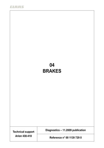
– Fit the pressure sensors of kit No.0001783100 onto a T on the level of the feed of one of the 2 brake pistons, one onto the hydraulic brake fitting of the "8036" trailer, and another onto the trailer pneumatic brake fitting.
– Connect tester No.0001783100 onto the pressure sensors. – Actuate the brakes over the entire stroke of the pedals. – Record pressure, which must be 70 bars for service brakes fitted with "boosters". The trailer hydraulic braking pressure is 140 +/- 5 bars. The trainler air braking pressure is 8 bars.
Note:Following this check, the brake system must be drained(Refer to chapter "04" in the preparation file).
"Booster" chart
Description(bar)
1 "Booster" brake pressure. 2 Trailer hydraulic brake pressure. 3 Trailer air brake pressure. These values are given as an indication only. Use the kit n°0001783100 to perform measurements and read then on a computer. The point is to display the curves of the different types of braking (service, brake, trailer hydraulic brake, air brake) to see if the tractor brakes the trailer properly. The graph below shows the braking of the master cylinder and "booster" with trailer hydraulic and pneumatic braking.
bar
160
140
120
100
80
60
40
20
0
0 3
c4002
7 10 14 17 21
24 1 2 3
28 3 1 s
Fig. 3