5 minute read
speed set value
Figure 2.1. Main control panel
2.3.1.1. Charger plug and safety socket (1)
The charger plug is used to charge the truck’s battery from a normal electrical mains supply with the internal charger. During normal operation, the charger plug is in the safety socket.The truck cannot be driven if the plug is removed from the socket. Refer to Section 2.6 Charging the batteries for more information on charging the truck’s battery.
2.3.1.2. Main key switch and emergency stop button (2)
The main key switch is used to control power from the battery to the truck’s electrical system.The switch is equipped with a key that can be removed to prevent unauthorised use.To remove the key, press it down, turn it counterclockwise and pull it out. When the key is in place, the truck’s power can be turned on by lifting the key to the up position. Press the key to the down position to turn off the truck’s power.
The key switch also functions as an emergency stop button. In an emergency, press the key downwards to remove electrical power from the truck.
10
2.3.1.3. Status LED (3)
The status LED gives an indication of the current state of the truck.When the truck is powered up, normally the status LED is constantly illuminated. If the status LED flashes, this may indicate an internal fault.
The status LED indicates the possible fault with a distinct repeating flashing sequence. For example, four flashes and a pause indicates a low battery.The error indication may also be due to incorrect operation. Switch off the truck's power and turn it back on with the tiller arm in the upright position and without giving the truck any commands through its controls while it starts up. If the status LED continues to flash, power down the truck and contact local maintenance staff.
2.3.1.4. Display unit (4)
The display unit shows the accumulated operating time of the truck in hours. It also displays the battery charge level. If an internal fault has occurred, the display unit also shows the error code.
2.3.2.Tiller arm head controls
The tiller arm head assembly contains the controls used for driving the truck and controlling the forks.
11

Figure 2.2.Tiller arm controls
2.3.2.1. Safety button (1)
The safety button is located at the far end of the tiller arm. Its purpose is to prevent the operator from being crushed between the truck and an object.The safety button is functional when the truck is being driven in the direction of the tiller arm. It is inactive in the other direction.
When the safety button is pressed while the truck is being driven in the direction of the forks, the truck immediately stops and reverses its movement for a short period.The intensity of this function depends on the speed of the truck. The operation of the safety button is verified as part of the daily maintenance checks, which must be performed
WARNING!
each day before using the truck. Never use a truck with a faulty safety button. Never use the safety button to manoeuvre the truck.
2.3.2.2. Lifting and lowering controls (2, 6 & 7)
Use these controls to lift and lower the truck’s fork carriage.The available controls depend on the truck model.
If only the lifting and lowering controls (2) on the front face of the tiller arm head are present, use them to lift and lower the fork carriage. Press up to lift the carriage and down to lower the
12
carriage. Note that the carriage can be lowered at two speeds. Press down lightly to lower the carriage slowly and press more firmly to lower the carriage faster.
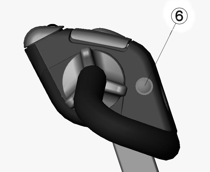
If the truck is equipped with the initial lifting function, this is controlled with push buttons (6) on either side of the tiller arm head assembly.The button on the right-hand side lifts and the button on the left-hand side lowers.

Figure 2.3. Push buttons (6) for controlling the initial lifting function
If the proportional lifting lever (7) is present, the height of the fork carriage can be controlled proportionally. Use the lifting lever (7) to position the carriage at the desired height. If the truck also has the initial lifting function, use the lifting and lowering controls (2) to control initial lifting and lowering. On a truck with proportional lifting but without the initial lifting function, the lifting and lowering controls (2) also control the fork carriage but not proportionally.
13

Figure 2.4. Proportional lifting lever (7)
2.3.2.3. Horn button (3)
Press this button to activate the truck’s horn.
2.3.2.4. Steering (4)
The truck is steered by moving the tiller arm from side to side. The drive wheel is directly connected to the tiller arm and turns with it.The tiller arm can be turned 100 degrees in both directions from the centre position.
The vertical position of the tiller arm affects driving:The truck can only be driven when the tiller arm is in the driving position, which is the area between the two extremes.The truck’s traction is disabled when the arm is in the upright or the bottom position. The restriction can be removed by pressing the brake release button.
2.3.2.5. Accelerator controls (5)
The two winged rotating wheels control the direction and acceleration of the truck.The movement direction is determined by the direction in which the controls are displaced from the neutral position.The amount of displacement determines the truck’s speed in the given direction.The accelerator control is also used to reduce the truck’s speed by either releasing it to the
14
neutral position or by turning it in the opposite direction to movement.
2.3.2.6. Brake release button (option)
The brake release button is located on the top of the tiller arm head.The brake release can be used to remove the driving restriction when the tiller arm is in the upright or the bottom position.This can be useful in confined spaces.The brake release is intended to be used in special situations and should not be used constantly.
2.3.3. PIN code lock
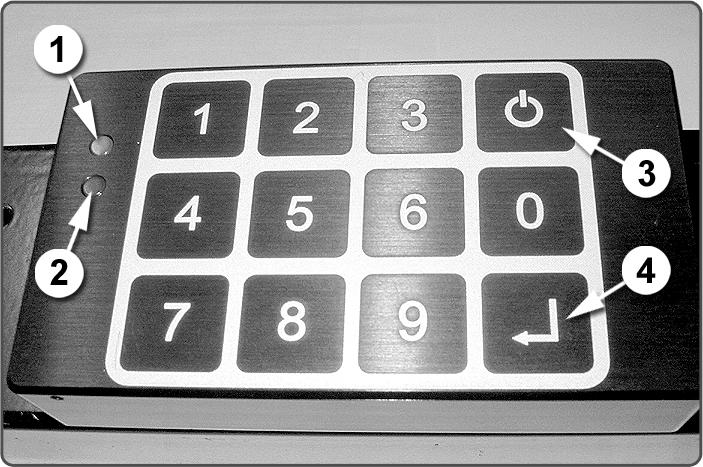
Some truck models are equipped with a PIN code locking device to prevent unauthorised use. An operator must enter a valid PIN code to activate and use the truck.The device can store up to 200 codes and one master code. One general code should be programmed into the device for emergencies, so that the truck can, for example, be moved quickly without a personal code.

Figure 2.5. PIN code locking device
To activate the truck, enter your PIN code on the keypad and press Enter (4). If a valid code was entered, the truck indicates this by illuminating the green indicator light (1).The truck is now activated and can be used normally. If the entered code is invalid, the red indicator light (2) illuminates for three seconds and the truck remains inactive. If an invalid code is entered three times, the red indicator light begins to flash. In this situation, the keypad
15


