1 minute read
Connections to Inlet Adapters and Turbochargers


flow pattern ahead of the turbocharger). Connections to Inlet Adapters and Turbochargers
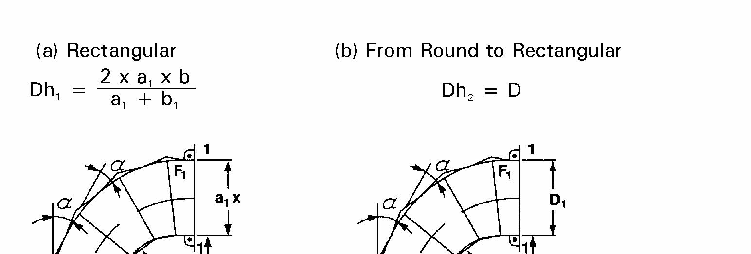
The piping connected to the turbocharger inlet should be designed to ensure that air is flowing in a straight, uniform direction into the turbocharger compressor. This is typically achieved by installing a straight section of pipe, equal in length to at least two or three times pipe diameter, to the inlet. This arrangement reduces the possibility of premature compressor wheel failure due to pulsations created by air striking the compressor wheel at an angle. Transitional ducting immediately preceding the straight section of pipe should consider the following guidelines: • The duct between the straight pipe and elbow cannot have protruding edges. • The bend can be designed as a circular arc or with sections of mitered pipe with rectangular or round flow cross sections, or as transition from round to rectangular cross section. • An accelerated flow is expected to occur in the bend. The flow area (F) should be: F1 > 1.5 x F2, as shown in Figure 6.
Turbocharger Vertical Inlet Design Options


Figure 6