6 minute read
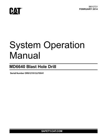
MAST STATUS SCREEN


NOTE: Pay close attention to the hoses, wires and cables that run between the mast support and the mast to prevent damage to the machine as the mast is being raised. Have a helper watch from a safe position on the left side of the machine as the mast is going up.
3. Once the mast is vertical, move the mast lock switch located on the mast screen on the operator’s display to the LOCK position to lock the mast in the vertical position. Mast Pins Locked light on operator’s display screen will illuminate when mast is locked in position. Turn the mast brace lock switch to the LOCKED position to secure the mast and brace in the vertical position.
NOTE: When moving the mast for angle hole drilling, on machines with mast lengths of 65 ft (19.8 m) or more, the drill pipe must be stored in the racks and the rotary head lowered to its lowest position.
4. If the mast is to be set up for angle drilling move the A-frame lock switch and the mast brace lock switch to the UNLOCK position to release the A-frame front leg lock pin and mast brace lock pins. The readout (A-Frame Pins Unlocked and Mast Brace Pin Unlocked) will show up on the mast status screen on operator’s display screen.
MAST STATUS SCREEN
5. Verify that the operation mode selector switch is still in the mast/winch position, then lift and pull the mast joystick slowly to the rear. Slowly lower the mast to the desired drilling angle, then turn the mast brace lock switch to the LOCKED position to secure the mast and brace in the desired position.
MAST LOWERING
NOTE: Refer to cautions at beginning of mast raising.
To lower the mast:
1. Level the machine.
2. Remove the drill pipe from the rotary drive unit and store it in the pipe racks. Remove the bit and stabilizer from the machine. Clear the drill deck of all tools and materials which could fall off during the lowering procedure. Secure the auxiliary winch hook. Be sure the auxiliary winch line is secured to the mast. Raise the dust curtains. Lower the rotary/pulldown unit to its lowest position.
3. Check the condition of the mast hinge pins, lugs and cylinder pins.
4. If the machine is set up for angle drilling and the mast is at an angle proceed to step 4. If the machine is set up for vertical drilling proceed to step 5.
5. Turn the mast brace lock switch to the UNLOCK position to release the mast lock pins, then raise the mast to the vertical position. Turn the A-frame lock switch to the LOCK position to lock the A-frame front leg. The readout (A-Frame Pins Locked) on the operator’s display will appear when the A-frame pins are in the LOCKED position. Now proceed to step 5 to lower the mast.
6. If the mast lock pins and/or mast brace lock switch have not been released, turn the switches to the UNLOCK position to release the pins. The readout (Mast Pins Unlocked and Mast Brace Pins Unlocked) will be shown on the operator’s display when the pins are released.
7. Slowly lower the mast by lifting and then pulling the joystick to the rear. As the mast moves away from the vertical position, its speed will increase. Gently reduce the lowering speed by moving the joystick toward neutral.

CAUTION: The joystick should be moved away from and returned to the neutral position very slowly. Sudden starts and stops can be damaging to the mast hydraulic system. Be extremely cautious as the mast approaches the mast rests, as only a slight movement of the control is necessary to cause motion in the mast. Lay the mast in the mast rests gently to prevent damage to the mast or machine house.
NOTE: Pay close attention to the hoses, wires and cables that run between the mast support and the mast to prevent damage to the machine as the mast is being lowered. Have the helper observe the machine from a safe position on the left side of the machine as the mast is coming down.
NOTE: Do not allow the mast, especially if near horizontal to lower too quickly. Damage may result from the mast hitting the mast reststoo hard.
8. Once the mast is resting in the mast rests, inspect the mast and the mast support to verify that no hoses, wires or cables are kinked or damaged. Repair any damages found immediately.
PULLDOWN MACHINERY OPERATION
Use of the pulldown machinery is necessary during the tool handling and the drilling procedures. The pulldown machinery supplies power to either raise or lower the rotary/pulldown unit. Power is supplied to the pulldown gearbox by an electric motor.
To operate the hoist/pulldown machinery proceed as follows;
1. Move the operating mode selector switch to the DRILL position.
2. Turn the hoist/pulldown selector switch to either PULLDOWN, HOIST HIGH, HOIST LOW, or PIPE RACK/JOINT.
For this procedure, turn the switch to the PULLDOWN position.
For a review of each switch position, refer to HOIST/PULLDOWN SPEED SELECTOR SWITCH.
3. Press the drill/propel control ON push-button. The Control Enable indicator will show on the operator’s display screen.
4. Turn the hoist brake switch to the RELEASE position. The Head Brake Released indicator will appear on operator’s display screen.
5. Rotate the hoist/pulldown rheostat in the hoist direction to hoist the rotary/pulldown unit. The farther the rheostat is turned to the right the faster the unit will be raised.
6. Rotate the pulldown force rheostat in the pulldown direction to lower the rotary/pulldown unit. The farther the rheostat is turned to the left the faster the unit will be lowered.
7. When the hoist/pulldown operations are complete, set the hoist/pulldown speed rheostat to the OFF position and then turn the hoist brake switch to the SET position.
CAUTION: Whenever the hoist/pulldown speed rheostat is in the OFF position, the hoist brake switch must be in the SET position to prevent the rotary/pulldown unit from creeping downward due to the weight of the unit.
AUXILIARY WINCH OPERATION
To operate the auxiliary winch proceed as follows:
1. Place the operation mode selector switch in the MAST/WINCH position.
2. To hoist the auxiliary winch line, lift and move the winch joystick, located on the right console, forward. To stop the line, return the joystick to the NEUTRAL position.
3. To lower the winch line, lift and move the joystick rearward. To stop the line, return the joystick to the NEUTRAL position.
PIPE RACK OPERATION
The machine can be equipped with 1 to 4 pipe racks and depending upon the number of pipe racks the pipe rack configuration and operation will be different.
On a machines with one pipe rack, the rack will be on a swing out arm and will be in #1 position .
On a machine with two pipe racks, the racks will be on swing out arms and will be in #1 and #4 positions.
On a machine with three pipe racks, two pipe racks will be located on a carousel that swings out and then is rotated. This carousel houses pipe racks in #1 and #2 positions as shown. The third pipe rack is a swing out rack that will be in #4 position.
On a machine with four pipe racks, there are two swing out carousels with two racks in each carousel. The carousels rotate to make each rack available for use. The left carousel houses racks #1 and #2 and the right carousel racks #3 and #4.
The general method of operating the pipe racks is as follows:
1. Place the operating mode selector switch in the DRILL position. The main air compressor must be energized.
2. Verify that the operating mode selector switch is in the DRILL position and that the hoist/ pulldown speed selector switch is in the PIPE RACK/JOINT position.
3. Select the desired pipe rack.
4. Lift and move the pipe rack joystick, located on the left console, out of neutral to perform the desired operation.