5 minute read
Stored Energy Signs


RAISE BOOM AND LOWER LOAD Extend arm horizontally with fingers extended and thumb pointing upward, alternately open and close fingers for the duration of the desired movement.
LOWER BOOM AND RAISE LOAD Extend arm horizontally with fingers extended and thumb pointing downward, alternately open and close fingers for the duration of the desired movement.
SWING Extend arm horizontally with index finger extended in desired direction of swing.
TRAVEL (Single Track) Use a raised fist on the side that remains locked and make a vertical circular motion in front of chest for the direction and side of desired movement.
EXTEND BOOM (Telescoping Booms) Place both hands in front of body with palms upward, fingers clenched, and thumbs extending outward.
RETRACT BOOM (Telescoping Booms) Place both hands in front of body with palms upward, fingers clenched, and thumbs extending inward.
EXTEND BOOM (Telescoping Booms) With fingers clenched and thumb extended toward body, use a single hand motion to tap on chest with thumb of hand.
RETRACT BOOM (Telescoping Booms) With fingers clenched and thumb extended away from body, use a single hand motion to tap on chest with heel of hand.
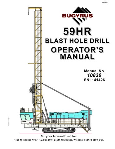
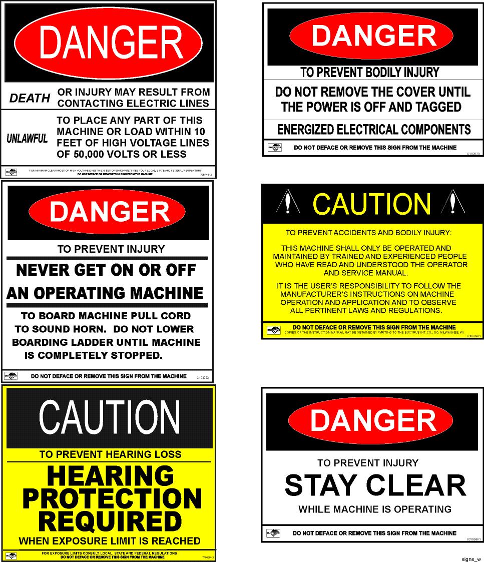
MACHINE PLACARDS
The images below depict an example of the warning placards mounted on the machine as it was delivered from Bucyrus International. These hazard warning placards convey information to operators, maintenance personnel, and anyone who will be on, or near, the machine. The information is designed to help prevent situations which will result in injury to personnel, or damage to the machine.
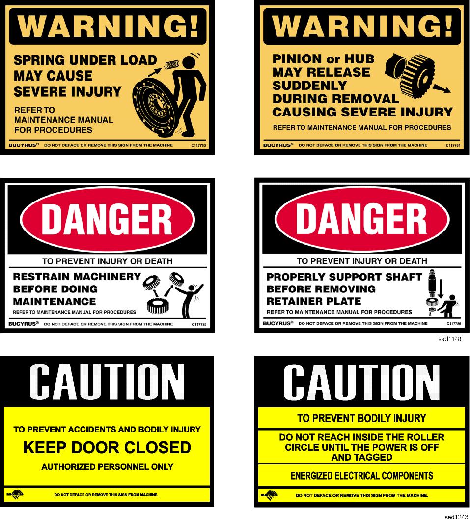
Stored Energy Signs
OPERATION NEAR ELECTRICAL TRANSMISSION LINES
Permission to reproduce the following material has been granted by the Construction Industry Manufacturers Association (CIMA). CIMA assumes no responsibility for the accuracy of this reproduction.
CAUTION: The following precautions shall be complied with whenever operating near electrical transmission lines.
Working in the vicinity of electrical power lines presents a very serious hazard and special precautions must be taken. For purposes of this manual you are considered to be working in the vicinity of power lines when the machine, in any position, can reach to within the minimum distance specified by local, state and federal regulations.
Safe operating practices require that you maintain the maximum possible distance from the lines and never violate the minimum clearances.
Be certain to comply with all local, state and federal regulations regarding working in the vicinity of power lines.
Before working in the vicinity of power lines, always take the following precautions:
1. Always contact the owners of the power lines or the nearest utility before beginning work.
2. You and the electric utility representative must jointly determine what specific precautions must be taken to insure safety.
3. It is the responsibility of the user and the electric utility to see that the necessary precautions are taken.
4. Consider all lines to be power lines and treat all power lines as energized even though it is known that the power is shut off and the line is visibly grounded.
5. Slow down the operating cycle. Reaction time may be too slow and distances may be misjudged.
6. Caution all ground personnel to stand clear of the machine at all times.
7. Use a signal person to guide the machine into close quarters. The sole responsibility of the signal person is to observe the approach of the machine to the power line. The signal person must be in direct communication with the operator and the operator must pay close attention to the signals.
CAUTION: Death or serious injury could result should any part of the drill come within the minimum distance specified of an energized power line.
MACHINE OVERVIEW
The machine is designed and constructed to provide efficient service under the most severe conditions. The machine is built to the highest possible standards and will provide trouble free operation if properly maintained.
PROPEL MACHINERY
The propel system of this machine is a chainless hydraulic drive system which will allow the separate tracks to counter-rotate. This capability provides the machine with the capacity to turn completely around within it’s own length. Each track is driven by a hydraulic motor and a planetary gearbox equipped with a hydraulically released, spring activated brake. The machine is capable of 2 different propel speed ranges. The lower speed range is used for maneuvering in close spaces while the high speed range is used for tramming in open areas, over long distances.
MAINFRAME AND DECKS
The machine mainframe consists basically of two I-beams tied together with bracing and covered on the top surface with deck plates.
MACHINERY HOUSE
MAIN AIR SYSTEMS
The screw compressor is located within the machinery house just forward of the hydraulic pump gearcase. The rotary screw compressor is an oil flooded, single stage twin screw type compressor.
HYDRAULIC SYSTEM
Hydraulic pressure for operation of this machine is provided by four separate pumps. These pumps are driven by the electric motor located in main machinery house, forward of the hydraulic filters and reservoir.
The machine has 2 separate, though not completely independent hydraulic systems, the OPEN and CLOSED circuits. Both draw fluid from a common reservoir.
OPERATOR’S CAB
The sound insulated operator’s cab of the machine provides a sealed, comfortable enclosure from which the operator can perform the tasks involved with the operation of the machine. The location and design of this compartment have been structured to provide the optimum viewing angles with immediate accessibility. The swivel mounted chair provides easy access to all required controls. The auxiliary control console is within reach to provide access to additional functions of the machine. The cab is provided with dual doorways to the main deck.
MAST
The mast is a fabricated structure made of steel tubes and formed plates. The structure is formed by four vertical tubes tied together on three sides with tubular lacing. The fourth side is open to allow the rotary drive unit to be raised and lowered the length of the mast.