37 minute read
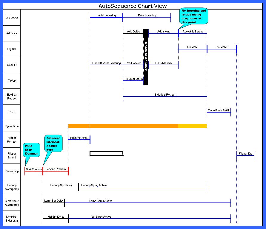
Autosequence Chart


List of Steps
The following Autosequence steps define the actions of the ASQ. Some steps could be skipped depending on the configuration of the shield because some functions may © Caterpillar
not exist. Also, some steps may run concurrently with other steps. The ASQ Begin step is always the first step triggered. When a step completes, it triggers one or more other steps. ASQ Begin First Prewarning Adjacent Shield Interlock Second Prewarning Flipper Retract Initial Lowering Extra Lowering Baselift While Lowering Pre-Baselift Advance Delay Tip Up or Tip Down Ready To Advance Baselift While Advancing Advancing Advance while Setting Initial Set Sideseal Extend Final Set Conveyor Push Refill Flipper Extend
ASQ Begin
If the shield ram stroke is not turned Off under the Sensor Status menu section and is less than the target stroke plus 2 percent, the ASQ will stop and post an error
(err: "ASQ ERROR shld already advanced").
Target stroke is set by parameter and by Wedge Advance logic.
If the shield is a transition shield, it is not allowed to advance until the adjacent shield on the gate-end side has advanced. If this does not happen within 60s, the ASQ stops and posts an error (err: "ASQ ERROR neighbor shld not adv"). If the above conditions are successfully met, the First Prewarning Step is triggered.
First Prewarning
The ASQ Step display shows “ * WARNING * ”. The First Prewarning is a 1.5s prewarning utilizing the internal warning light and beeper and also the connected KH led-based light. After this step, the Adjacent Shield Interlock Step is triggered.
Before the ASQ continues, messages are exchanged with the neighbor shields to make sure that neighbor shields are not attempting an ASQ at the same time. This interlocking process prevents any shield from beginning an ASQ if the adjacent shield is already ASQing. The adjacent shield interlock is not released until the active ASQ has started the Initial Set step. For this step to complete, at least one neighbor shield must have a leg pressure reading that is greater than the 100 bar or must have both leg pressure sensors disabled. If more than 20s pass without this occurring, the ASQ will stop and post an error (err: "ASQ ERROR adj pressure too low"). After this step, when neighbor shields have been successfully locked, the following steps are triggered: Second Prewarning
Second Prewarning
The Second Prewarning lasts for 1.5s. The prewarning actions started in the First Prewarning continue during the second prewarning and throughout the rest of the ASQ. After this step, the Flipper Retract Step is triggered.
Flipper Retract
To ensure that the flipper does not interfere with the shield advance, the Flipper Retract feature provides the option of retracting the flipper prior to lowering the shield. The Flipper Retract option is an On/Off option set by parameter “Retract Flipper“. If set to Off, no action is taken. If set to On, the Flipper Control function is commanded to retract the flipper and the ASQ Step display shows “flipper ret”. See the Flipper Control function for details of the flipper retract action.
Parameter “Retract Flipper”
If the Flipper Control function fails to successfully retract the flipper, the ASQ stops and posts an error (err: "ASQ ERROR flipper failed to ret"). If the Flipper Control function successfully retracts the flipper, the following steps are triggered: Baselift While Lowering Initial Lowering Side seal retract
This is an optional feature controlled by parameter “Baselift During Lower” which is set to On or Off. If set to Off, no action is taken. If set to On, the Baselift function is activated during the Initial Lowering. (Baselift While Lowering is triggered at the same time as Initial Lowering and ends when Initial Lowering ends.) The end of Baselift While Lowering triggers no other steps.
Parameter “Baselift During Lower”
Initial Lowering
Initial Lowering is not optional – it always occurs. The leg lower function is activated. The ASQ Step display shows “legs lower”. The end of Initial Lowering is determined by several parameters.
For the Initial Lowering to be successfully completed, the leg pressure reading(s) must fall below (or equal to) the value given by parameter “Advancing Pressure” within the time given by parameter “Initial Lowering Time”.
Parameters “Advancing Pressure” “Initial Lowering Time”
If parameter “Contact Advance” is On, the Initial Lowering is complete as soon as the leg pressure requirement is met. If “Contact Advance” is Off, the leg lower action continues for the full time and the leg pressure reading(s) are evaluated at the end to ensure the requirement is met.
Parameter “Contact Advance”
If the leg sensor is invalid or turned Off under the Sensor Status menu section, the lowering will be based on time regardless of the “Contact Advance” parameter. If Advancing Pressure is not reached, then the ASQ terminates and posts an error (err: “ASQ ERROR adv press not reached”) and, to ensure roof support is maintained, triggers the Final Set Step. During the initial lowering, if the first 1s passes with no substantial change in leg pressure, the lowering function will be cycled off for 0.5s and then restarted. This is only allowed to happen once. The 0.5s of “off” time counts against the “Initial Lowering Time”.
Stuck-valve detection
If Initial Lowering ends without error, it triggers the following steps: Pre-Baselift Tip Up or Down Advance Delay Extra Lowering
Extra lowering provides for additional roof clearance by continuing the leg lower function during the shield advance. If parameter “Extra Lowering Time” is set to 0, the feature is effectively switched Off, the leg lower function is deactivated immediately and Extra Lowering ends.
Parameter “Extra Lowering Time”
Otherwise, the leg lower function remains active until the Extra Lowering Time expires or until Initial Set begins. At that time, the leg lower function is deactivated and Extra Lowering ends. The end of Extra Lowering triggers no other steps.
Pre-Baselift
The Pre-Baselift feature allows for a minimum time period of baselift prior to the shield advance. This is only necessary if the baselift was not activated during the Initial Lowering (i.e., parameter “Baselift While Lowering” is set to Off) but is desired during advancing (i.e., parameter “Baselift While Advancing” is On). If this is the case, then this time applies: the baselift function will be activated for a time specified by parameter “Pre-Baselift Time” (which may be 0). The function is not released at the end of this step. The end of Pre-Baselift triggers the Ready To Advance Step.
Parameters “Baselift While Lowering” “Baselift While Advancing” “Pre-Baselift Time”
Tip Up or Tip Down
The Tip Up or Tip Down feature provides optional tip action after lowering but before advancing. Headgate shields will tip down to avoid the roof bolts. The time of this tip down is given by parameter “Headgate Tip Down Time”. All other shields will tip up. The time of the tip up is given by parameter “Tip Up Time”. Either of these parameters may be set to 0 to eliminate the associated tip action.
Parameters "Headgate Tip Down Time" “Tip Up Time”
If Contact Advance is On, then this parameter value will be displayed as “X by Contact Advance” and the tip-up action will not occur. When Contact Advance is switched Off, then the “Tip Up Time” parameter will revert from “X by Contact Advance” back to the numerical value. The end of Tip Up or Tip Down step triggers the Ready To Advance Step.
Advance Delay
The purpose of advance delay is to allow for additional roof clearance after contact advance has terminated the initial lowering step. This allows the ASQ to take advantage of Contact Advance’s more precise control and faster cycle times while still providing some additional roof clearance prior to advance. Advance Delay is only used when Extra Lowering time is greater than 0 and Contact Advance is On. The delay occurs during the Extra Lowering time while the shield is continuing to lower.
The time of the delay is set by parameter “Advance Delay Time”. If the parameter is set to 0, the feature if effectively turned Off.
Parameter “Advance Delay Time”
It is only a delay – no additional functions are activated. The end of the Advance Delay triggers the Ready To Advance Step.
Ready To Advance
The Ready To Advance step is used to trigger the rest of the ASQ after the completion of all of the following steps which trigger it: Pre-Baselift Advance Delay Tip Up or Tip Down. The Ready To Advance step activates no functions and adds no delay. After Ready To Advance has been triggered by all three of the above steps, it ends and triggers the following steps: Advancing Baselift While Advancing
Baselift While Advancing
Baselift While Advancing is triggered along with the shield advance to activate the baselift function during the advance if the parameter “Baselift During Adv” is On. It remains active until the Initial Set step begins or the ram stroke reaches (or falls below) the value set by parameter
"Baselift Drop Stroke".
The end of this step triggers nothing else.
Parameters “Baselift During Adv” "Baselift Drop Stroke"
Advancing
The Advancing step activates the advancing function and ends when the ram stroke reaches the target advance stroke or when the limiting time is reached. The ASQ Step Display will show “* Advancing *” The limiting time is set by the parameter “Maximum Advancing Time”. The target advance stroke is usually determined by parameter “Advancing Tgt Stroke” which is usually set to a low number, the minimum being 2. If a wedge command has been entered, the target stroke will be determined by the wedge calculation. See the Wedge Advance section on page 43 for more details.
Parameters “Maximum Advancing Time” “Advancing Tgt Stroke”
If the ram stroke does not drop by at least 5% every second, an error is posted (err: “ASQ ERROR slow advance”), the Advancing Step ends and the Relowering Step is triggered.
If the Advancing Step ends due to the limiting time, an error is posted (err: "ASQ ERROR 1st advance timeout"), the Advancing Step ends and the Relowering Step is triggered. If the ram stroke reaches the target stroke, the Advancing Step ends, the shield advance function is deactivated if the target stroke is greater than 2%, and the following steps are triggered: Advance while Setting Initial Set
Relowering
The Relowering step is the first step in the ASQ retry logic which is activated when the Advancing step is unable to successfully advance the shield. The shield advance function is deactivated. (Baselift and waterspray functions are left in their existing state.)
If parameter "Retry Count" is 0, then the Relowering Step ends and the following steps are triggered: Advance while Setting Initial Set
Parameter "Retry Count"
If this is the Nth retry where N is given by parameter "Tip Down on Retry", the Tip Down function will be activated for a time given by parameter "Tip Down Time" and the ASQ Step display will show "Tip Down". Remaining actions in the Relowering step do not occur until the Tip Down Time has expired.
Parameters "Tip Down on Retry" "Tip Down Time"
The Lowering function is then activated and the ASQ Step display will show “*Relowering*”. The relowering step is time limited by the parameter
"Relowering Time".
The end of the Relowering step triggers the Readvancing step.
Parameter "Relowering Time"
Readvancing
The Readvancing step stops the lowering function and activates the advancing function. The ASQ Step display will show “*ReAdvancing*”. If the ram stroke reading reaches the target advance stroke, the Readvancing step ends and triggers the following: Advance while Setting Initial Set
If the limiting time given by parameter "Maximum Advancing Time" is reached the Readvancing step will trigger the Relowering step.
Parameter "Maximum Advancing Time"
Advance While Setting
This feature allows the advancing function to remain active during the Initial Set to prevent the shield from sliding backwards as roof pressure increases. If parameter “Advancing Tgt Stroke” is set to 2, then this step keeps the advancing function active until the end of the Initial Set step; if it is set to 3 or greater, then the program assumes it really is supposed to stop short of a full advance and the advance function is shut off. Once the function is deactivated, the step is completed.
Parameter “Advancing Tgt Stroke”
The end of this step triggers nothing else.
Initial Set
This step activates the leg set function and sets the shield until contact with the top is reached. The ASQ Step display will show “Setting”. This step ends when the leg pressure reading reaches 50 bar or when the limiting time is reached. If the leg pressure reading is switched Off in the Sensor Status menu section, then this step will be limited only by the time parameter. The limiting time for the initial setting is the total time that the leg lower function was active during the ASQ. The baselift function is deactivated at the beginning of this step. Adjacent-shield interlocks are released when this step starts. See Adjacent Shield Interlock step. The set function is deactivated at the end of this step only if the step ends due to the limiting time, except when there is no active leg sensor. The end of this step triggers Final Set Conveyor Push Refill
Final Set
The Final Set step is responsible to set the shield to the target setting pressure. The ASQ Step display will show “Setting”. If the leg set function is not active, this step waits for 0.5s and activates it. This will happen if the Initial Set step times out and deactivates the function.
The leg set function remains active until the leg pressure reading reaches parameter “Final Set Pressure” or until the limiting time is reached. If the leg pressure reading is switched Off in the Sensor Status menu section, then this step will be limited only by the time parameter. The limiting time is set by parameter “Final Set Time”.
Parameters “Final Set Pressure” “Final Set Time”
If the Final Set Time expires before the Final Set Pressure is reached, an error is posted (err: "ASQ ERROR set press not reached"). The set function(s) are deactivated at the end of this step. Normally, the end of this step triggers the Flipper Extend step. *If this state was triggered by an Umbrella Lock, then an error is posted (err: "ASQ ERROR pause – umbrella lock") and the end of this step triggers the Umbrella Lock Pause step.
Conveyor Push Refill
This step activates the conveyor push function for a short time period set by parameter “ram refill time”. If the time is set to 0, the feature is effectively switched off. This feature closes the clevis pin gap at the conveyor to keep the pan from moving backwards when nearby shields advance or when the shearer passes. The end of this step triggers no other steps.
Parameter “ram refill time”
Flipper Extend
The Flipper Extend option is an ON/OFF option set by parameter “Extend Flipper”. This is a global parameter and does affect all the shields on the face. If set to Off, no action is taken. If set to On, the Flipper Control function is commanded to extend the flipper and the ASQ Step display shows “flipper ext”. See the Flipper Control function for details of the flipper extend action.
Parameter “Extend Flipper”
There are local parameters that will prohibit all flipper functions or by adjusting the parameter “HG Cancel Flip Extend” or parameter “TG Cancel Flip Extend”, located in the ASQ parameters, a number of shields in the gate areas can be prevented from extending the flipper during an Autosequence.
The end of this step is the end of the Autosequence.
Parameters “HG Cancel Flip Extend” “TG Cancel Flip Extend”
Umbrella Lock Pause
This state posts an error (err “ASQ ERROR paused - umbrella lock”). This state exits when the Umbrella Lock is removed or when the limiting time expires. The limiting time is 90 seconds. © Caterpillar
If this step ends due to the limiting time, the ASQ stops and an error is posted (err: "ASQ ERROR abort - umbrella lock"). If this step ends because the Umbrella Lock is removed, it triggers the First Prewarning step.
Errors
ASQ ERROR main hyd pressure low
ASQ paused because the main hydraulic pressure was too low.
ASQ ERROR paused – umbrella lock
Umbrella Lock caused ASQ to pause; will resume if umbrella removed soon enough.
ASQ ERROR abort – umbrella lock
ASQ aborted because Umbrella Lock remained more than 90s.
ASQ ERROR aborted
ASQ aborted by Quickstop, Lockout, Stop key, etc.
ASQ ERROR shld already advanced
ASQ did not begin because this shield appears to be advanced (see parameter Advancing Tgt Stroke).
ASQ ERROR neighbor shld not adv
ASQ aborted because transition shield didn't advance within 60s.
ASQ ERROR adj pressure too low
Adjacent shield leg pressure too low. At least one neighbor shield must have at least one leg pressure reading of 100 bar or more.
ASQ ERROR flipper failed to ret
Flipper failed to completely retract prior to leg lower.
ASQ ERROR adv press not reached
Legs did not lower enough for adv to begin; see parameters Advancing Pressure and Initial Lowering Time.
ASQ ERROR slow advance
Shield advancing too slowly.
ASQ ERROR 1st advance timeout
Shield not fully advanced before parameter Advancing Time expired.
ASQ ERROR advance failed
The shield failed to advance; check Retry Count, Relowering Time, Readvance Time.
ASQ ERROR set press not reached
Legs did not reach Final Set Pressure within Final Set Time
ASQ ERROR adj shield locked
Black lockout button is pressed on adjacent shield.
ASQ ERROR flipper failed to ext
Flipper failed to completely extend after legs set.
ASQ ERROR network
ASQ aborted because of broken net.
ASQ ERROR no ram sensor
ASQ was trying to wedge advance but didn't have a usable ram sensor reading.
ASQ ERROR operator on shield
ASQ aborted because an operator was on the shield pressing keys.
ASQ ERROR leg pressure invalid
One or both legs are invalid. Replace or turn off sensor.
ASQ ERROR luminaire blink fail
ASQ not allowed unless able to blink KH luminaire.
Parameter Summary
ASQ Status Enabled, Disabled
Enables or Disables ASQ in this single shield.
Retract Flipper ON, OFF
Option to retract flipper at beginning of ASQ.
Baselift During Lower ON, OFF
Activate the baselift function while lowering the legs.
Initial Lowering Time 200-1000
Length of time to allow for legs lower at start of ASQ.
Advancing Pressure 50-150
Legs must get below this pressure to allow the shield to advance.
Contact Advance ON, OFF
Option to begin advance as soon as legs reach advancing pressure.
Extra Lowering Time 0-1000
Continue lowering legs during advance for this amount of time.
Pre-Baselift Time 0-200
If Baselift During Lower is Off and Baselift During Advance is On, this sets the length of time for baselift to activate before advance begins.
Tip Up Time 0-100
Length of time that line & tailgate shlds tip up after lowering before advancing.
HG Tip Down Group 0-5
Number of shields at HG that will tip down during ASQ.
Headgate Tip Down Time 0-100
Length of time that headgate shields tip down after lowering before advancing.
Advance Delay Time 0-300
Only when Contact Advance is On and Extra Lowering is > 0; delay advance for this time to allow extra roof clearance before advance begins.
Baselift Drop Stroke 0-80
Drop baselift when ram stroke reaches this value.
Baselift During Adv
Option to baselift during shield advance.
ON, OFF
Maximum Advancing Time
Time allowed for shield advance.
0-1500
Retry Count 0-3
How many times shield will retry after first attempt to advance.
Tip Down on Retry 0-3
Sets which retry the shield will tip down on.
Tip Down Time 0-200
Length of time shield will tip down on retry.
Relowering Time
Length of leg lower on retries.
0-500
Final Set Time 0-2000
Length of time after roof contact that setting continues while trying to reach Final Set Pressure.
Final Set Pressure 0-350
Target leg pressure that ASQ attempts to reach.
Ram refill time 0-150
Length of time for ram push fct to stay active at end of ASQ to tighten clevis connection.
Extend Flipper
Option to extend flipper at the end of ASQ.
ON, OFF
HG Cancel Flip Extend 0-20
Sets # of shields at headgate that will NOT extend flipper during autosequence.
TG Cancel Flip Extend 0-20
Sets # of shields at tailgate that will NOT extend flipper during autosequence.
Next Advance Tgt Stk 0-100
Next stroke for advance to stop if programmed to do a wedge advance
HG Seq First Shield 1-15
First shield to advance in the HG Sequence Group
HG Seq Last Shield 1-15
Last shield to advance in the HG Sequence group.
TG Seq First Shield 1-15
First shield to advance in the TG Sequence Group
TG Seq Last Shield 1-15
Last shield to advance in the TG Sequence group.
Some of the commonly used group functions can be accessed using the group function hot keys. First the Group Function key is pressed first followed by a Group Select key. The function is then activated by pressing the Start key.
Press > Then > Then > Results
Selects a group of shields to the right and triggers an Autosequence on each. The batch mode determines the sequence of movement. Parameter “Group size” determines how many shields will be selected.
Selects a group of shields to the left and triggers a conveyor pullback on each. The shields will continue to pullback until the target stroke is reached or they timeout. Selects a group of 10 shields to the immediate left and triggers all of them to push the conveyor to the Bankpush “Tgt Stroke” parameter or until they timeout. Pressing the F-key twice will cause 20 shields to be selected. The push starts with the farthest shield and travels toward the nearest shield. This direction can be reversed by pressing the N-key (red up arrow). The direction is indicated by an arrow on the display.
Starts SRB with the shearer moving to the right.
Selects a group of shields to the left and does a manual conveyor pullback on each. As long as the last key is held the shields continue to pullback stopping only when the target stroke is reached.
Other group functions are activated by scrolling to the appropriate line using the Menu Navigation keys and then pressing the Group Select key and the Start key.
B a t c h A d v a n c e
Batch Advance is the Group Automatic function that allows the operator to advance an adjacent group of shields efficiently. Last Auto Fct is posted on each shield as “Batch ASQ”.
Operator Display and Keystrokes
Press > Then > Then > Results
Selects a group of shields to the right and triggers an Autosequence on each. The batch mode determines the sequence of movement.
Selects a group of shields to the left and triggers an Autosequence on each. The batch mode determines the sequence of movement.
Keystroke Details
The operator presses the Batch Adv key to see the Batch Advance display (or manually scrolls to Group Automatic Fcts -> Batch Advance display).
: B a t c h A d v a n c e : x x x d y y y t y p e s t r i n g
“xxx” and “yyy” are the beginning and ending shield numbers that are selected. “d” is the direction indicator (< or >). The direction determines whether xxx or yyy is the beginning or ending shield. The direction is only visible in sequential & rabbit modes since it does not apply to standard mode. “xxx” and “yyy” are invalid (~~~) when the Batch Adv key is first pressed; they are filled in when the Group Select key is pressed. Typestring will show the mode of batching that is selected. The values will revert back to invalid when Key-time expires after the Start key is pressed. “typestring” is the Batch Advance Mode. Mode options are described below. The operator must choose a group of shields to the left or right using the Group Select keys. When the Group Select key is pressed, the beginning and ending shield numbers will appear on the Batch Advance display. The number of shields selected is determined by Batch Advance parameter "Group Size". If Group Size is 5 and the operator is on shield 100 selecting shields on the tailgate side, then shields 101 through 105 will be selected.
Parameter “Group Size” I want to pull the shields to my right so…
When the Batch Adv key is pressed, the direction will be set so that the shield farthest away from the operator pulls first. It can be toggled using the Menu Red Arrow key.
to toggle direction
The Menu Green Arrow key toggles the typestring between Sequential, Rabbit, and Standard mode. The Mode options are described below.
After reviewing the selected shields, the direction, and the mode, press the Start key to start the Batch Advance.
to toggle mode
Everything looks good so…
Prewarning / Active Display
After the Start key is pressed, every shield in the selected group will display the ASQ Active display and begin prewarning (for more information, see Prewarning / Active Display in the ASQ Section on page 27). But the ASQ is not triggered yet; the Batch Advance logic triggers the ASQs based on the batch mode as described below.
Operating Logic & Modes
Sequential Mode
In Sequential mode, the Batch Advance triggers the Autosequence function one shield at a time; the direction indicator identifies which shield starts the process. Each shield fully completes its ASQ before the ASQ is triggered in the next shield. Sequential Mode is subject to the parameter "Batch Advance Max Time" setting. Any shield that is not triggered within this time will post an error
(err: "BATCH ERROR Timed Out").
Rabbit Mode
Rabbit mode triggers the ASQs in every other shield, one at a time, waiting for one shield to begin advancing before triggering another shield. This mode is faster than sequential mode while still retaining excellent roof support in the batch area.
Standard Mode
This is the fastest mode and is the mode that is normally used. However, this mode places the highest demand on the hydraulic supply system and provides less roof support during the batch operation than the other modes. The other modes will seldom be used but may help in adverse roof conditions or times when hydraulic pressure or volume is reduced. Standard mode triggers all even-numbered shields first (all together), waits for 1s and triggers all odd numbered shields (all together). The purpose of the delay is to allow the even number shields to begin the Autosequence first. The Autosequence Interlock logic will prevent the odd shields from beginning to ASQ until the even shields have finished.
Batch Advance has no enable / disable options. However, individual shields can be restricted from Batch Adv operation by the Batch Status local parameter.
Restrictions
Batch Advance is subject to the standard Automatic Function restrictions. In addition, Batch Advance cannot be started if it is already running.
Errors
BATCH ERROR Timed Out!
Batch Advance Max Time is too short or ASQs are too slow.
Parameter Summary
Grp Size 2-10
Number of shields selected when Group Select key is pressed.
Max Time 1000-3000
Max time allowed for all ASQs in Batch to complete.
Batch Status Allowed, Not Allowed
Determines if shield is allowed to be involved in a Batch Advance.
W e d g e A d v a n c e
The Wedge Advance feature allows the operator to set an area of the face for wedge advance which will occur in the future. The operator selects the shields to be included, and the target stroke for the first and last shields in the group. The shields don't actually move at this time; they are just designated for wedge advance the next time that something causes them to ASQ.
Operator Display & Keystrokes
To set a wedge, the operator scrolls to Group Automatic->Set Wedge Advance display: : S e t W e d g e A d v a n c e : # b b b , x x x # e e e , y y y
bbb and eee are the beginning and ending shields that are selected. xxx and yyy are the target stroke for the beginning and ending shields. (100% means the shield will not attempt to advance at all; 0% means the shield will attempt to advance completely.)
If the operator likes the values shown, it is only necessary to press the Start key and the Wedge Advance command is sent to the face. The shields in the selected wedge area will all show " -Wedge Advance" on the top line. This means that the wedge has been queued and the partial advance will occur on the next ASQ.
Wedge Advance Queued
The beginning and ending shield selections and the target stroke settings are adjustable by scrolling right from the Wedge Advance display (Menu Right key) to reveal the Wedge Advance parameters. The values are then entered as normal parameters (using the Enter key and number keys). After the parameters are entered, the Menu Left key will shift the display back to the Wedge Advance display and the Start key is pressed to trigger the Wedge Advance.
To cancel all Wedge Advances that have been set anywhere on the face, the operator scrolls to the Wedge Advance display and into the Wedge Advance parameters to the “Clear All Wedges (N)” display. When the Menu Red Arrow key is pressed, all wedges are cleared.
Hmm, does not look good… Manually enter parameter values, then….
Wedge Advance Queued
Hmm, I want to cancel the wedges… Clear All Wedges (N)
Prewarning / Active Display
Setting a Wedge Advance does not cause any prewarning to activate. It does post a default display to indicate that a Wedge Advance is queued. Line2 will continue to show sensor values; line1 will show "#87 -wedge advance" for example.
Operating Logic
When the operator presses the Start key to set the Wedge Advance, a message is sent from the operator’s shield to the "beginning" shield in the Wedge Advance. From there a message is passed toward the "ending" shield. Each shield calculates its own Wedge Advance target stroke and activates the Wedge Advance default display. Wedge Advance can be "overlayed" with any other function. That means that once the wedge command has been entered, the ASQs can be activated by Batch Advance, SRB, or adjacent control. In all cases, the ASQ will follow the pending wedge advance target stroke. After the ASQ occurs, the wedge is no longer queued, the wedge advance indication is cleared from the display, and subsequent ASQs will advance the shield normally. If a Wedge Advance is already set and a new wedge command is received, the new command takes precedence.
There are no enable / disable options for the Wedge Advance feature.
Restrictions
Since wedge advance is not a feature that actually moves shields, the normal restrictions do not apply.
Errors
This feature does not generate any errors.
Parameter Summary
Beginning Shield 1-310
First shield in the wedge advance area.
Beginning Shld Stroke 0-100
How far the first shield will advance.
Ending Shield 1-130
Last shield in the wedge advance area.
Ending Shield Stroke 0-100
How far the last shield will advance.
B a t c h P u l l b a c k
Batch Pullback is the Group Automatic function that allows the operator to pull the conveyor backwards in a controlled way. Batch Pullback works in a group of shields adjacent to the operator. Last Auto Fct is posted on each shield as “Pullback”.
Operator Display & Keystrokes
Press > Then > Then > Results
Selects a group of shields to the left and triggers an automatic conveyor pullback on each. Pullback will continue until the target stroke is reached or they timeout. Selects a group of shields to the right and triggers a manual conveyor pullback on each. Pullback will continue until the target stroke is reached or the key is released.
Keystroke Details
The operator presses the Pull Back key to see the Batch Pullback display (or scrolls to the Group Functions Column to the Batch Pullback display).
: B a t c h P u l l b a c k : x x x d y y y s t k %
“xxx” and “yyy” are the beginning and ending shields that are selected. “xxx” and “yyy” are invalid (~~~) when the Pull Back key is first pressed; they are filled in when the Group Select key is pressed. The values will revert back to invalid when Key-time expires after the Start key is pressed. “d” is the direction indicator (< or >). The direction determines whether xxx or yyy is the beginning or ending shield. “stk%” is the target stroke percentage, set by Batch Pullback parameter “Tgt Stroke”. The operator must choose a group of shields to the left or right using the Group Select keys. When the Group Select key is pressed, the beginning and ending shield numbers will appear on the Batch Pullback display. The number of shields selected is determined by Batch Pullback parameter "Group Size". If Group Size is 10 and the operator is on shield 100 selecting shields on the tailgate side, then shields 101 through 110 will be selected.
Parameter “Group Size”
Pressing the Red Arrow key toggles the direction, changing which end of the group will start pulling first.
Automatic Mode
To start the pullback operation in automatic mode, the operator just presses the Start Key. (After Key-time expires and the screen reverts to the default display, the beginning and ending points shown on the Batch Pullback display will revert back to invalid (~~~).
to toggle direction
Hmm, I want to pull the shields to my right so…
Manual Mode
To start the pullback operation in manual mode, the operator presses and holds the Pull Back key. When the Pull Back key is released, the pullback action immediately stops. If the key is pressed again before Key-time expires, the action will start again. In both modes, the pullback action will stop at the target stroke.
or maybe I should use manual pullback, so…
Prewarning / Active Display
When the pullback direction is selected (via the Group Select Left or Right key) the selected shields will prewarn and display the Conveyor Pullback display. The display © Caterpillar
Operating Logic
After the direction is selected and the Start key is pressed (or the Pull Back key is held), the prewarning sounds and the CPull-active display is shown. The Batch Pullback logic will ensure that no shields in the selected group will be delayed by current reservation (i.e., each shield will pre-reserve enough current to activate the pullback valve) and waits until at least 3s of prewarning time has passed. If 10 seconds passes without being able to pre-reserve current, the pullback will terminate and the operator’s shield will post an error (err: "PULLBACK ERROR current reservation"). The shields are then triggered consecutively, based on the direction indicator. The delay between triggering shields is set by parameter “Delay Time” under Configuration->Conveyor Pullback.
Parameter "Delay Time"
When the pullback function is triggered, the prewarning sound is muted but remains active as long as the pullback function is active. If the manual mode is being used, when the operator releases the Pull Back key, the pullback action will stop. Parameter "Tgt Stroke" sets the target stroke for the pullback. The conveyor will be pulled to this stroke value except at the ends of the group where the Conveyor Pullback protection logic will taper the pullback to avoid overstressing the conveyor and ram connections.
Parameter "Tgt Stroke"
Conveyor Pullback Protection
The Conveyor Pullback delta protection allows the shield to only pullback 10% more than the neighbor shields. Example: 20 shields are selected to the left to do a pullback. The target stroke was set to 50%. The shield at the far end could pull back only to 90% because the next shield is outside of the pullback area. The next shield in the pullback area can pull to 80%, the next to 70%, etc. The same would happen on the end nearest to the operator. This could mean that only certain shields in the middle of the group would reach their target stroke of 50%. When delta protection stops the pullback, it is only temporary; the pullback logic is still triggered but the hydraulic function is deactivated and the pullback status display changes to "< delta" or "delta >" depending upon which neighbor shield triggered the delta protection. As soon as the ram stroke difference falls to 5%, the pullback resumes. Delta protection does not suspend the Conveyor Pullback Timeout feature.
Delta protection
10% difference in strokes allowed
If the target stroke is set greater than 20%, a valid ram reading is required. If the ram reading is invalid or turned Off under the Sensor Status menu section, an error is posted (err: "PULLBACK ERROR invalid ram sensor"). Shields within parameter "Abort Dist" on either side that are part of the pullback will be aborted and will post an error (err: "PULLBACK ERROR aborted by #xxx"). The Abort Dist parameter is under Configuration->Conveyor Pullback.
Parameter “Abort Dist”
Shield Up protection is designed to protect the conveyor from damage during the conveyor pullback operation. If a shield has been advanced, pulling the conveyor across that shield will break something in the ram/conveyor connection. Shield Up protection will prevent the pullback from occurring in this situation.
Conveyor Push has "Shield Back" protection – Conveyor Pullback has "Shield Up" protection!
At the beginning of the pullback action, if a shield has a ram stroke that is more than 20% less than either of the adjacent ram strokes, it is assumed that the shield has been advanced. It will post an error (err: "PULLBACK ERROR shield is advanced"); shields within parameter "Abort Dist" on either side that are part of the pullback will be aborted and will post an error (err: "PULLBACK ERROR aborted by #xxx"). This check only happens at the beginning of the pullback action.
Shield Set to Roof
At the beginning of the pullback action, the shield should be set to the roof as indicated by an active leg pressure reading of 100bar or more. If this requirement is not met, an error will be posted (err: "PULLBACK ERROR low leg pressure") and shields within parameter "Abort Dist" on either side that are part of the pullback will be aborted and will post an error (err: "PULLBACK ERROR aborted by #xxx"). If the leg sensor is inactive (turned Off under the Sensor Status menu section), the pullback will be allowed outside the Shearer Safety zone; but inside the Shearer Safety zone the error will be posted. This check only happens at the beginning of the pullback action. It is intended to protect against causing the shield to advance instead of pulling the pan back due to the lack of roof pressure.
Conveyor Pullback Timeout
The conveyor pullback is always limited in duration. Parameter "Max Time" found under Configuration->Conveyor Pullback sets the maximum time period the pullback will remain active. If the pullback times out before reaching the target stroke, an error will posted (err: "PULLBACK ERROR pullback timeout").
Parameter "Max Time"
Snake Area
To keep the snake area of the pullback from beeping and showing "delta" for a long time, if the ram stroke doesn’t change for more than 5s, the pullback function is © Caterpillar 48
Enable / Disable Options
Batch Pullback has no enable / disable options.
Restrictions
Batch Pullback is subject to the standard Automatic Function restrictions. Additionally, an active ASQ will prevent Batch Pullback from being triggered and will abort an already-active Batch Pullback.
Errors
PULLBACK ERROR invalid ram sensor
Pullback stopped due to invalid ram sensor.
PULLBACK ERROR aborted by #xxx
Pulback aborted by msg from another shield.
PULLBACK ERROR Shield is advanced
Pullback aborted because this shield already advanced.
PULLBACK ERROR pullback timeout
Pullback failed to complete in time; chk Conveyor Push Time.
PULLBACK ERROR low leg pressure
Pullback aborted due to insufficient leg pressure.
Parameter Summary
Tgt Stroke 0-100
Tells Batch Pullback how far to pull in percent.
Group Size 1-30
Sets number of shields selected for pullback.
Abort Dist 3-5
Distance on each side that will abort if a shield is already up.
Max Time 2000-9000
Max time in hundredths of a second for pullback to complete.
Start Group 0-5
Number of shields that will activate at the same time at the start of the conveyor pullback.
Delay Time 0-1000
Delay between each of the shields activating in the conveyor pullback after pullback start group is active.
B a n k p u s h
The Bankpush function allows the operator to push the conveyor in a controlled way in any area of the face no matter where the operator is located.
The operator can activate the Bankpush function in two different ways. The operator can manually enter the start and end points (this allows a push to be started at any location on the face) or the operator can use the adjacent-bankpush feature and select a group of 10 or 20 adjacent shields for the bankpush. Shields that are part of a bankpush post "Bankpush" as the Last Auto Fct. !Caution: It is NOT recommended to push where the shearer is located due to the stress it may put on the shearer.
Operator Display & Keystrokes
Press > Then > Then > Results
Selects a group of 10 shields to the left and triggers conveyor push on each. Push will continue until the target stroke is reached or they timeout.
Selects a group of 10 shields to the right and triggers conveyor push on each. Push will continue until the target stroke is reached or they timeout.
Selects a group of 20 shields to the right and triggers conveyor push on each. Push will continue until the target stroke is reached or they timeout.
Triggers conveyor push based on existing parameter values shown in the display. Often the values are entered by the operator just prior to using this key combination by scrolling right after pressing the Bank Push key and manually changing the values.
Keystroke Details
The operator presses the Bank Push key to see the Bankpush display (or scrolls to the Group Functions Column to the Bankpush display).
: B a n k p u s h : x x x d y y y s t k %
“xxx” and “yyy” are the beginning and ending shields that are selected. “xxx” and “yyy” may be invalid (~~~) when the Bank Push key is first pressed; they are filled in when the Group Select key is pressed. The values are retained and do not revert back to invalid when Key-time expires after the Start key is pressed.
“d” is the direction indicator (< or >). The direction determines whether xxx or yyy is the beginning or ending shield. “stk%” is the target stroke percentage, set by Bankpush parameter “Tgt Stroke”.
Pressing the Red Arrow key toggles the direction, changing which shield pushes first.
to toggle direction
If the operator likes the beginning and ending shield selections shown and the target stroke value, it is only necessary to press the Start key and the bankpush operation will be triggered on those shields.
Hmm, looks good...
Batch Operation
Rather than manually entering the start and end points, from the Bankpush display the operator can use the Group Select keys to select a group of 10 shields to one side. When the Group Select key is pressed, the Begin and End parameters will be changed and the change will be seen on the Bankpush display. If the same Group Select key is pressed again, the group size will be extended from 10 to 20 shields. To start the Bankpush operation, the operator just presses the Start key.
Hmm, instead of entering parameters, I just want to choose 10 shields to the left
or maybe 20 shields…
Prewarning / Active Display
When the operator presses the Start key the selected shields will prewarn and display the Bankpush Active display. The display will retain the default line2 (showing sensors values, etc) while line1 will show " ! BPUSH ! " followed by text that indicates the current action.
Operating Logic
Following the initial 3s of prewarning, the push action will begin at the one end of the group and travel toward the other, depending on the direction indicator. The Bankpush logic simultaneously triggers the Conveyor Push action on a group of shields at the beginning of the selected bank. The remaining shields will be triggered one at a time. The operator should select a Bankpush group that completely overlaps the snake left by the previous push. For example, if the operator is 10 shields away from the closest shield that has pushed, activate a push that reaches back 20 shields ensures that all shields get pushed completely and a bow is not left in the face.