6 minute read
Operating Logic


The operator can trigger a push of the gate shields by pressing the Bank Push key twice and then pressing start. B a n k P u s h G a t e E n d . . . p r e s s S t a r t
This only works from the first twenty shields for the Headgate and the last twenty for the Tailgate push. The active display will show "Gate Push: delta >", "Gate Push: < delta", or "Gate Push: active" as appropriate.
Belt Tailpiece Controller
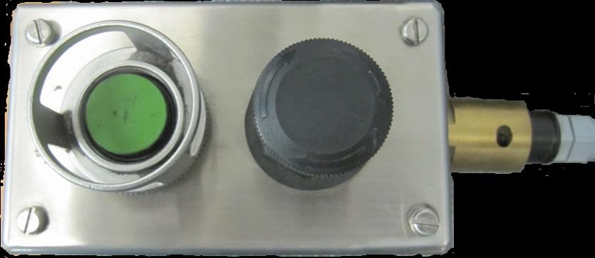
The belt tailpiece controller connects to the server and allows the operator to pause the headgate push, until the mobile tailpiece is in place, then from the belt tailpiece controller the gate push can be activated. When the black button is pressed in, the gate push is disabled and from the control shield to #1 shield will all display Btp locked. When the belt tailpiece is ready the operator presses the green button 3 times to initiate the end gate push.
Prewarning / Active Display
The top line of the display will indicate what triggered the Conveyor Push (SRB, GatePush, LockPush or Bankpush). Conveyor Push updates the current action information on the display to show what is happening: active - actually pushing delta - waiting on an adjacent shield to push farther gateend - waiting for other gateend shields to push so the gate pushes evenly Last Auto Fct will be posted as "Manual Push", "SRB Push", "Bankpush", or "Endgate Push".
Operating Logic
The Conveyor Push feature offers several methods of protection to prevent damage to the equipment.
Shield Back protection
Shield Back protection is designed to protect the conveyor from damage during the conveyor push operation. If a shield is left back (not advanced) pushing the conveyor will break the relay bar or clevis connection. Shield Back protection will prevent the push from occurring in this situation.
At the beginning of the push action, if a shield has a ram stroke that is 25% more than either of the adjacent ram strokes, it is assumed that the shield has been left back. O/S will post an error (err: "PUSH ERROR shield back"). Shields within a distance set by parameter "Abort Dist" (under Configuration->Conveyor Push) on either side that are pushing will be aborted and will post an error (err: "PUSH ERROR aborted by #xxx").
Parameter “Abort Di
This check only happens at the beginning of the push action, when Conveyor Push is triggered. Because Shield Back protection depends on the ram stroke readings of the shield and its neighbor shields, the “Push Protection” parameter is provided to define what action to take when a ram sensor is invalid. See the following section.
Push Protection Parameter
The parameter “Push Protection” (under Configuration>Conveyor Push) controls how the Shield Back protection is applied. There are three different setting for the parameter:
FULL
Parameter “Push Protection”
“Full” protection means that sensors are required. If a shield or either neighbor has an invalid ram sensor then the shield is treated as if it is back because the ram strokes can not be compared. If a ram sensor is turned Off using the local “Ram Position” parameter under the Sensor Status menu section, then the Push Protection for that shield is effectively reduced to “Partial” as described below.
PARTIAL
Parameter “Ram Position”
“Partial protection” allows Push Protection to operate when a shield and the neighbor(s) both have valid, “On” ram sensors. If either shield has an invalid or “Off” ram sensor then no error is posted; it is just assumed that pushing will not cause a problem.
NONE
“None” means that Push Protection is completely disabled. The push is allowed to continue without checking to see if a shield has been left back.
To provide a conveyor snake that is more gentle than the mechanical limits of the conveyor, Delta Protection is provided. Delta protection can be enabled or disabled using the parameter “Delta Protection” under Configuration>Conveyor Push.
Parameter “Delta Protection”
During the push action, a shield will stop pushing if the ram stroke exceeds either neighbor by "delta". Delta is defined like this…
Ram Stroke Delta
<75% =>75% 15% 10% When delta protection stops the push, it is only temporary; the push logic is still active but it is suspended: the hydraulic function is de-activated and the push state string changes to "< delta" or "delta >" depending upon which neighbor shield triggered the delta protection. As soon as the ram stroke difference falls to half of delta, the push resumes. For example, the push will suspend when it reaches 15% if the neighbor is still at 0%; when the neighbor reaches 8%, the push will re-activate. While the shield is “delta-ed” the Conveyor Push time continues to run.
Conveyor Push Timeout
The conveyor push is always limited in duration. Parameter "Max Time" under Configuration->Conveyor Push sets the maximum time period the push will remain active.
Parameter "Max Time"
Target Stroke
The target stroke feature stops the conveyor push at a pre-determined ram stroke reading set by the function that triggered the push (Locking Push key, Bankpush, Endgate Push, or SRB). If the push times out before reaching the target stroke, an error will be posted. (err: "PUSH ERROR conveyor push timeout").
Endgate Even-push Feature
The Endgate Even-push Feature is designed to make gate shields pushing evenly so the drive frame is not twisted. At each end of the face, there is a parameter to define a control shield that determines how far the other shields can push; and there is a parameter to determine how many shields at the endgate are subject to this restriction. The Endgate Even-push Feature only applies to automatic modes of conveyor push.
Parameters “Headgate Push Ctl” and “Tailgate Push Ctl” (both under Configuration->Conveyor Push) define which shield is the controlling shield at each end of the face. If set to 5, then the first 4 shields will not push until the 5th one is ready to push.
Parameters "Headgate Push Ctl" “Tailgate Push Ctl”
Parameters “Headgate Push Group” and “Tailgate Push Group” define the number of shields at each endgate that will be controlled by this feature. If “Headgate Push Ctl” is 5, all shields that are in the Headgate Push Group cannot push more than 10% greater than the controlling shield, which is number 5. If one of these shields has a sensor that is invalid or turned Off, that shield just pushes for time. This would work the same for the tailgate end of the face but with respect to the Tailgate Push Group.
Parameters “Headgate Push Group” “Tailgate Push Group”
If the controlling shield or the adjacent shield (on the mid-face side) has a ram sensor that is invalid or turned Off, the controlling shield will be shifted towards mid face until an acceptable controlling shield is found. Once the controlling shield has shifted, it does not shift back until power cycles or the Headgate Push Ctl is changed. When this feature has paused the push action, the Conveyor Push action text on the top line will show "gateend –".
Triggering Method Affects Operation
Which safety and control methods are used depends upon how the conveyor push was triggered.
Trigger Push Mode Notes
In-shield Locking Push key Adjacent Locking Push key Manual Applies: Conveyor Push Timeout Target Stroke Timeout Target stk (optional) Does not apply: Shield back protection Delta protection
SRB BankPush Endgate Push Automatic Applies: Shield back protection Delta protection Endgate even-push Timeout Target Stroke