17 minute read
INSTRUMENTSAND CONTROLS


Blakefield South FBL-55H Service Manual
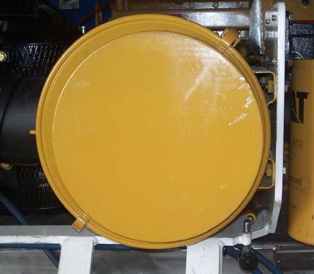
INSTRUMENTS AND CONTROLS Compartment door
The compartment door must be closed and locked after entering the compartment before the park brake button can be released and the declutch valve deactivated.
Maintenance
Grease door latch and hinges weekly and ensure interlock door valve is secure.
WARNING Never use the door to apply the park brake. Always manually apply by the park brake button and ensure the brake head pressure gauge reads zero. The steering pressure will automatically bleed down, never assume the steering pressure has bled down unless the steering pressure gauge reads zero.
NOTICE When the door is open the machine cannot be operated, as the park brake will be on and the transmission will be declutched. There is a roller cam valve in the door lock that needs to be activated, to release the park brake. Also the brake system pressure is dumped with the door open. The engine will run with the door open.
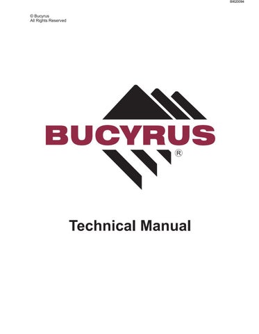
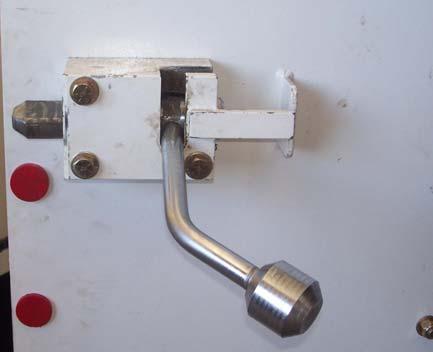
Compartment Door Latch
Door Interlock Valve
Blakefield South FBL-55H Service Manual
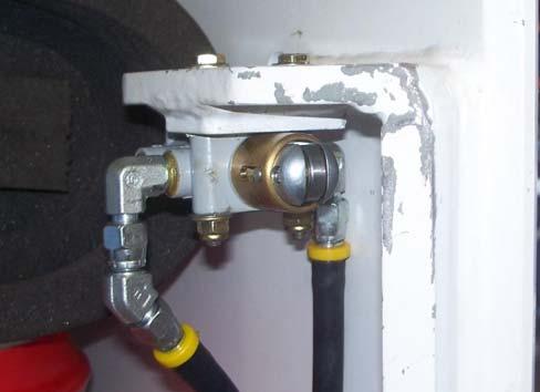
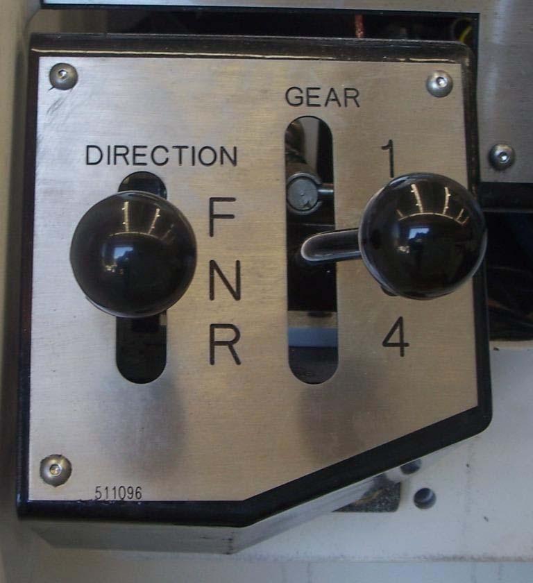
Transmission gear control lever
The gear control lever has four positions, first, second, third and fourth.
Maintenance
Lubricate cable and linkages if hard to shift gears.
NOTICE The transmission in the machine is modulated. This prevents severe shocks being transmitted through the drive train when the transmission is shifted between gears.
Transmission Directional Control Lever
A directional control lever controls the transmission. This lever has three positions, forward, neutral and reverse. The engine should be at low idle when the transmission is shifted from the neutral position to either forward or reverse direction.
Maintenance
Lubricate cables if hard to shift gears.
NOTICE The transmission must be placed in the neutral position for the starter motor to engage when starting the engine.
WARNING If the engine starts when the transmission is not in neutral the neutral start on the transmission needs to be adjusted or replaced.
Transmission Directional Control Lever Transmission Gear Control Lever
Transmission Controls
Blakefield South FBL-55H Service Manual
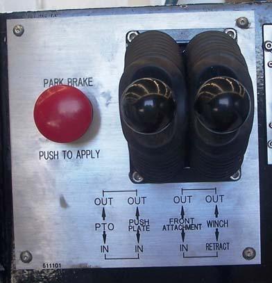
Park Brake button
The park brake button has two positions and it is held in the release position by pilot air pressure. By pushing the button inwards, the park brake is applied, and by pulling the button out the park brake will be released. The park brake cannot be released until the system pressure is sufficient to overcome the spring force of the brake control, it also will not release unless the door is closed (there is a roller cam valve inside the door lock which needs to be activated to release the park brake). If the engine shuts down the park brake will automatically apply itself by dumping the pilot air pressure via the low oil pressure pilot valve. The brake head pressure gauge must read zero when the brake is applied.
WARNING Never use the door interlock to actuate the park brake when exiting the machine. If there is a malfunction on the door interlock system, the park brake could possibly not apply when exiting machine and the machine could run away resulting in serious damage or injury.
NOTICE The park brake must be applied for the starter motor to engage whenever an engine start is required.
Park Brake Button
Brake Head Pressure Gauge
Blakefield South FBL-55H Service Manual
Four-Way Joystick Control Lever
This lever has five positions, tilt back, tilt forward, lift, lower and hold. Pushing the lever to the right tilts the RAS back plate back for loading and tramming. Pulling the lever to the left tilts the RAS back plate forward for digging or unloading. Pushing the lever forward lowers the lift arms. Pulling the lever back raises the lift arms. The lever is spring centred to the hold position.
NOTICE Two functions may be engaged at the same time by pushing the four-way joystick control lever at 45° in the direction of the two required functions.
No. 1 - Two-Way Hydraulic Control Lever
There are two hydraulic two-way control levers fitted to the machine. The first lever closest to the operator is used to control attachments and engage and disengage the RAS locking tongue. This lever has three positions, up, down and hold. The lever is spring centred to the hold position. When operating an attachment, the function of this lever alters depending on the attachment fitted.
NOTICE To release attachments, the RAS Pilot Lock Cylinder Release Button must be pushed simultaneously whilst pulling down on the lever. This is to prevent an accidental uncoupling of the attachment
No. 2 - Two-Way Hydraulic Control Lever
The second lever, furthest from the operator, is used to control RAS attachments. This lever has three positions, up, down and hold. The lever is spring centred to the hold position. When operating an attachment, the function of this lever alters depending on the attachment fitted.
NOTICE On some machines an auxiliary hydraulic PTO (Power Take Off) may be fitted to the rear of the machine. This lever controls this function.
No. 1 - Two-Way Hydraulic Control Lever
No. 2 - Two-Way Hydraulic Control Lever Four Way Control Lever
Blakefield South FBL-55H Service Manual
Control Lever Maintenance Maintenance
Inspect the tilt/lift and attachment control valve for damaged or missing boot or parts and replace as necessary. Carry out operational performance test as per Section 7.1 of Bucyrus Australia Preventative Maintenance Inspections if replacement is required.
Control Levers
Blakefield South FBL-55H Service Manual
Operator’s Seat
On the operator’s seat the height, backrest tilt and seat suspension are all adjustable. The controls for these functions are beside the seat. Some machines are fitted with a swivel seat which may need lubricating from time to time, a seat belt is fitted to the seat assembly that needs to be inspected for correct operation and replaced if required
Accelerator pedal
The accelerator pedal is connected to the engine fuel pump governor via a cable. When the accelerator pedal is depressed the engine speed increases. The accelerator pedal is spring return so that when pedal pressure is removed, the engine returns to low idle.
CAUTION! Always keep the operator’s compartment clean. Dirt, etc. can build up under the accelerator pedal restricting its movement.
Brake pedal
The brake pedal when depressed applies the brakes on the front and rear axles. There are four liquidcooled Posi-Stop brakes located internally in each wheel end. Whenever possible use the engine compression to slow the machine on a grade or decline by selecting a lower gear and driving the machine using engine revs.
CAUTION! Do not ride the brakes while tramming the machine.
NOTICE! If the engine should stall, the machine is fitted with fail-safe brake system that will fully apply the brakes. The operator can apply the brakes at any time following an engine stall to immediately bring the machine to a controlled stop.
CAUTION! Always keep the operator’s compartment clean. Dirt, etc. can build up under the brake pedal restricting its movement.
Blakefield South FBL-55H Service Manual
Steering Wheel
The steering wheel controls the flow of hydraulic oil to the steering cylinder via an orbital steering valve. As the cylinder strokes, the machine articulates to the left or to the right. Turning the wheel anti-clockwise articulates the machine towards the operator. This effectively turns the machine to the left in the forward direction (lift arm end). Turning the wheel clockwise articulates the machine away from the operator. This effectively turns the machine to the right in the forward direction (lift arm end).
NOTICE The machine will turn in the opposite directions when travelling in forward and reverse. Operator training and familiarity with LHD operation is important to ensure that collisions are avoided.
NOTICE If the engine should stall, the machine is fitted with a system that will dump the steering pressure. The operator can steer the machine via a six litre back up accumulator at any time following an engine stall to immediately bring the machine to a safe controlled stop.
NOTICE If the door is opened or the park brake is applied, the machine is fitted with fail-safe steering system that will immediately dump the steering system pressure. This is to protect the operator or personnel from being crushed in the articulation area. Steering cannot be used until the door is shut and latched and the park brake button pulled out to the released position.
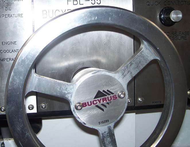
Steering Wheel
Blakefield South FBL-55H Service Manual
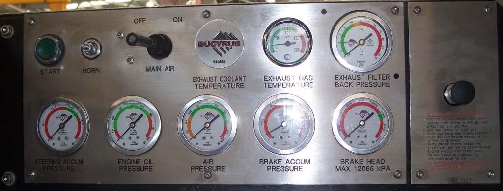
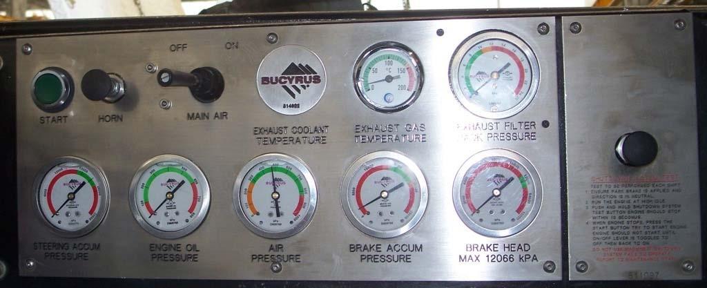
Brake Head Pressure Gauge
This gauge shows the service and park brake system’s brake head pressure. Operators should periodically check this gauge. The gauge will read zero pressure when the brakes are fully applied via the service and/or park brake controls
NOTICE! If the operator’s foot is off the brake pedal and the park brake is released, the indicated pressure shall be a minimum of 12000 kPa (1750 psi). If the pressure is below this it is likely that the brakes are dragging. The machine shall not be operated with dragging brakes as fire or brake failure may result. Immediately report the problem to service personnel. CAUTION! Observe that the brake head pressure is on zero after applying the park brake.
Brake Accumulator Pressure Gauge
This gauge indicates the service and park brake system’s accumulator pressure. Normal operating system pressure is 17200 kPa (2500 psi).
CAUTION! Do not operate the machine if the brake accumulator pressure gauge is less than 17200 kPa (2500 psi). Immediately report the problem to service personnel.
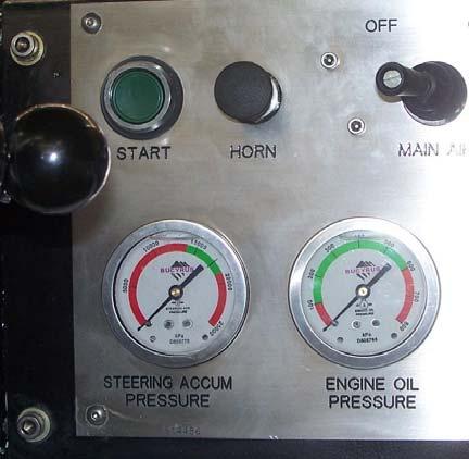
Steering Accumulator Pressure Gauge
This gauge indicates the steering system’s accumulated pressure. Normal operating system pressure is 17200 kPa (2500 psi).
NOTICE! If the pressure constantly drops below or will not hold 17200 kPa (2500 psi), steering may become difficult. The machine should not be operated and the problem shall be reported immediately to service personnel.
Steering Accumulator Pressure Brake Accumulator Pressure
Right Hand Side Operators Panel Brake Head Pressure
Blakefield South FBL-55H Service Manual
Engine Start Button
Depressing the engine start button engages the starter motor to start the engine. The engine start button will not activate the starter motor unless: 1) The transmission is in neutral. 2) The park brake is applied. 3) The diesel control system shows no fault. 4) The on/off toggle switch is on. 5) Sufficient air is in the receiver and air valve is turned on.
NOTICE! Depress the accelerator pedal ⅓ before a start to ensure sufficient fuel is available. Immediately remove finger from the engine start button when the engine fires.
Air Pressure Gauge
This gauge indicates the air pressure in the air receiver. Normal air pressure is set at 760 kPa-860 kPa (110 psi -125 psi).
NOTICE! The main air isolation valve is mounted in the engine compartment. Turn this valve on before entering the machine. The gauge will read zero when the valve is shut.
On/Off Toggle Switch
The on/off toggle switch controls the supply of pilot air pressure to the air pressure switch on the diesel control system, which allows air to pilot the start motor. 1) To start the engine, place the on/off toggle switch in the on position. 2) To shutdown the engine, place the on/off toggle switch in the off position.
Engine Start Button
ON/OFF Toggle Switch
Air Pressure Gauge Right Hand Side Operators Panel
Blakefield South FBL-55H Service Manual
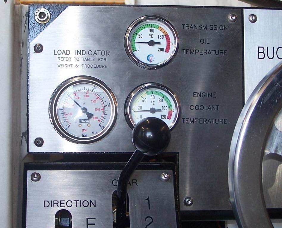
Transmission Oil Temperature Gauge
This gauge indicates the oil temperature in the transmission and torque converter. Normal oil temperature is between 82°C-93°C. If the temperature should rise above 121°C, carry out the following procedure: 1) Bring the machine to a halt, lower the lift arms to the ground and apply the park brake. 2) Put the transmission in neutral and run the engine to approximately ½ speed. Observe the temperature gauge for about two minutes. If the temperature does not begin to fall within two minutes, shutdown the machine and do not attempt to operate it until corrective action has been taken. Immediately report the problem to service personnel.
Transmission Oil Temperature Gauge
Left Hand Side Operator’s Panel
WARNING! Do not operate the machine if the oil temperature is above 121°C.
CAUTION! Transmission temperature can be affected by incorrect gear selection for the load being carried and or the road conditions.
Blakefield South FBL-55H Service Manual
Load Indicator Gauge
This gauge indicates the load pressure at the cap end of the lift cylinders. Refer to the load indicator table below for the procedure to determine the load/ pressure relationship.
Load Indicator Gauge
WARNING! Do not operate the machine with a load greater than its rated capacity of 60T (210Bar load gauge pressure).
CAUTION! Overloading the machine beyond its rated load capacity could cause catastrophic machine failure, injury and even death.
Blakefield South FBL-55H Service Manual
Load Indicator Table
Blakefield South FBL-55H Service Manual
Engine COOLANT Temperature Gauge
This shows the coolant temperature circulating through the engine radiator system. Normal operating temperature is between 82°C-95°C. The engine should not be operated under heavy load until it has had time to warm up approximately five minutes. The engine must also be shut off and cooled when the coolant level is to be topped up.
WARNING! Shut off the engine immediately if the coolant temperature gauge goes above 105°C. The diesel control system will give an alarm at 100°C and should shutdown the engine at 105°C.
Left Hand Side Operator’s Panel Engine Coolant Temperature Gauge
Blakefield South FBL-55H Service Manual
Horn Button
Pushing this button sounds the air horns.
NOTICE! It is good operating procedure to sound the horn 2-3 seconds before an engine start or whenever approaching blind intersection.
Right Hand Side Operators Panel Horn Button
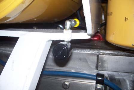
Emergency Fuel Shut Off Valve
This valve is located after the fuel filter/water separator. Closing this valve will stop the flow of fuel to the engine. This provides a second means of shutting down the engine should the on/off toggle switch fail.
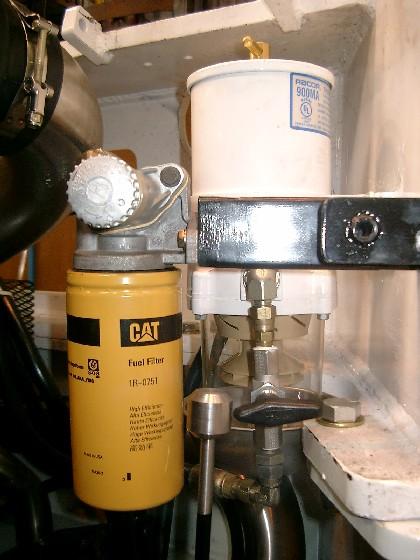
Emergency Fuel Shutoff Valve Shown in the closed Position
Blakefield South FBL-55H Service Manual
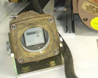
Engine Service Hour Meter
This electric meter is mounted on the off driver’s side at the rear of the machine. Use the hour meter to determine servicing intervals.
Air Cleaner Service Indicator
The air cleaner service indicator is located at the air cleaner and indicates the condition of the air cleaner element. When the service indicator is in the red zone, the air cleaner elements should be removed and serviced.
Engine Hour Meter
Air Cleaner and Indicator
Blakefield South FBL-55H Service Manual
Engine Oil Pressure Gauge
This gauge indicates the engine lubricating oil pressure. Normal pressure is between 210 kPa-550 kPa (30 psi-80 psi) at rated RPM.
CAUTION! Shut off the engine if the oil pressure drops and stays below 70 kPa (10 psi). The diesel control system should shutdown the engine at 70 kPa (10psi).
CAUTION! Do not run the engine with low oil pressure, as engine damage will result. Immediately report the problem to service personnel.
Outlet Gas Temperature Gauge
Engine Oil Pressure Gauge Right Hand Side Operators Panel
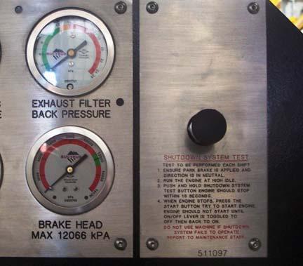
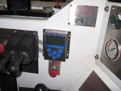
Shutdown System Test Valve
The test valve is used to check the integrity of the Fail-Safe Shutdown System. This test should be carried out on a daily basis as part of the 10 Hour Daily Off Line Mechanical Inspection. (Refer to Section 8 - Post Start Checks).
Test Button
Blakefield South FBL-55H Service Manual
Engine Fuel Primer Pump
If the engine fuel system has been run dry or serviced, the fuel system should be primed via manual activation of the hand fuel primer pump. The pump is located adjacent to the fuel water separator in the engine compartment. Normally no priming is required to start the engine. To prime the fuel system: 5) Fill the fuel tank with the recommended grade of fuel. If it is not possible to completely fill the tank then add a minimum 50 litres to the tank. 6) Unlock the fuel priming pump plunger and operate in an in and out motion until resistance is felt, a considerable amount of stroke may be required. 7) Push in the plunger and tighten by hand. 8) Promptly start the engine, if the engine runs rough increase the engine RPM to approximately ½ the rated RPM and check for fuel leaks
Attachment Quick Connects Button
This button releases all of the pressure in the PTO lines to allow the couplings to be easily released. To release the pressure, release both of the two-way control levers to the hold position and press in the pressure release button for two seconds.
Fuel Primer Pump
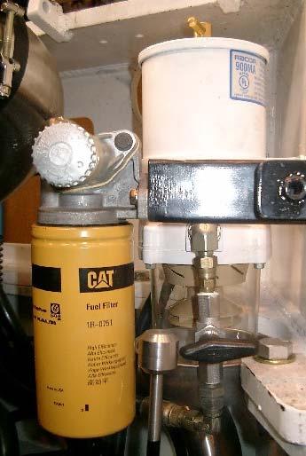
Engine Fuel Primer Pump
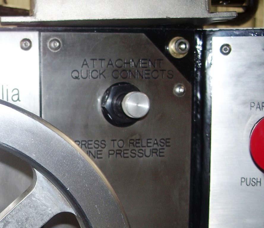
Attachment Quick Release Button
Blakefield South FBL-55H Service Manual
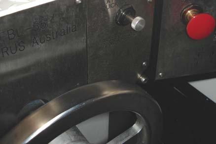
Emergency Intake Shut Off Valve
This valve is used in the event that the machine fails to shutdown under normal circumstances as stated in Section 8. Closing this valve will stop the flow of air to the engine. This provides a second means of shutting down the engine should the on/off toggle switch fail.
The valve is activated from the operator’s compartment by a stop button which is pushed, once activated and the engine shuts down the valve will need to be reset before restarting. Ensure that the stop button has been pulled out and there is a reset lever down on the main body of the valve that will rotate and latch into the operating position. If the valve has not been reset the engine will not start. When the valve has been reset the engine can be started.
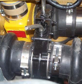
Emergency Intake Shut Off Valve Stop Button Emergency Intake Shut Off Valve Reset Lever Emergency Intake Shut Off Valve Reset Lever
WARNING! If the emergency intake shutoff valve has been activated, the restarting of the engine should be done in compliance with the relevant regulations and Manager’s Rules.
WARNING! This engine system is fitted with a wet exhaust conditioner. Operation of the Emergency Intake Shut off valve while the engine is running may result in exhaust conditioner water being drawn back into the engine. This may result in catastrophic damage to the engine. WARNING! ONLY RESTART THE ENGINE AFTER VERIFYING THAT THERE HAS BEEN NO INGRESS OF WATER FROM EXHAUST CONDITIONER INTO THE ENGINE. THIS IS TO BE VERIFIED BY SERVICE PERSONNEL PROIR TO ATTEMPING ENGINE START
Manual LOP Fire Suppression System Actuator
This valve should be used in the event that a machine fire occurs to activate the fire suppression system manually. Note that this actuator is used as a manual backup to the automatic fire suppression system. If a fire occurs, the manual LOP actuator can be operated as follows: 1) Remove the safety pin. 2) Strike the knob firmly.
Blakefield South FBL-55H Service Manual
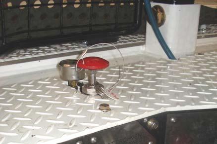
Manual LOP Fire Suppression System Actuator
Once the fire suppression system is activated, a transducer that monitors the fire suppression system will automatically shutdown the engine within 3 seconds.