19 minute read
Section 24 Attachments and Accessories


Section 24 Attachments
GENERAL DESCRIPTION
The Rapid Attach System (RAS) is specifically designed to provide safe attachment and retention of a range of accessories used on the machine. The RAS system basically comprises of an attach plate, retaining tongue and hydraulic power take off permanently fixed to the front frame (see Section 6).
The attachments are the machine’s working tools covering a wide range of applications including materials load haul dumping, heavy load handling and personnel elevation.
The operator and maintenance personnel must be trained and authorised to use and maintain the equipment and its attachments.
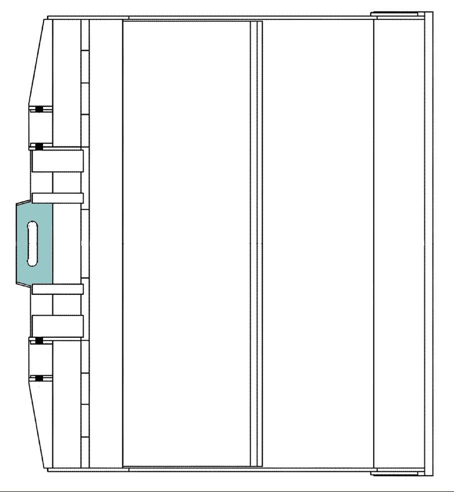
Attachments are designed to be secured to the RAS attach plate and lock tongue. Once the PTO hoses are disconnected after the lock tongue is engaged they can be used for various functions on the attachments. A second pair of PTO lines is available on the off driver’s side for an additional power take off such as the use of side shift forks or CHT-50 functions where independent control is provided.
RAS Lock Tongue Indicator
RAS Attach Plate
RAS Lock Cylinder
RAS Lock Tongue
RAS Attach Plate General Description
The FBL-10 and the FBL-10 RAS assemblies are different, the FBL-10 is a much larger and higher capacity assembly. The attachments can not be interchanged between models. (Reference Photos 1 and 2 Page 80). The CHT-50 can be interchanged by changing the 5th wheel assembly.

FBL-10 RAS Attach Plate General Description


FBL-10 RAS Attach Plate General Description
SAFETY PRECAUTIONS
The following safety precautions are not intended to be exhaustive. Safe work procedures and Safe Work Method Statements should be used when servicing or operating heavy machinery.
ALWAYS Isolate the machine/implement before working on any RAS attachment.
ALWAYS Follow the site tagging and isolation procedures.
ALWAYS Follow site transport rules.
ALWAYS Relieve the attachment quick connect line pressure via the button valve on the dash panel before disconnecting from the attachment.
ALWAYS Disconnect the hydraulic lines to the RAS lock cylinder once the attachment is in place to ensure that the attachment is not accidentally released. The lock cylinder hydraulic lines can either be connected to the hydraulic system of the attachment or to the dummy blocks located on the lift arm assembly.
ALWAYS Isolate the machine/implement before working on any RAS attachment.
ALWAYS Remove the attachment from the RAS attach plate when raising the lift arm for maintenance.
ALWAYS Install the lift arm lock when access under the lift arm assembly area is required. Remove any RAS attachment before raising and locking the lift arm assembly.
ALWAYS Use extreme caution when tramming the machine with the attachment raised.
ALWAYS Lower the load as close as possible to the ground when tramming.
NEVER Walk underneath a raised lift arm with the bucket or other attachment connected
NEVER Load the attachment beyond the rated load carrying capacity.
EJECTOR BUCKETS
SPADE LIP EJECTOR BUCKET
Various size ejector buckets are available, all with common operation and servicing requirements. Two double acting hydraulic cylinders actuated from the PTO lines on both sides of the lift arm assembly operate a hinged ejector plate for material discharge.
Specifications:
Unladen Mass: 3696 kg Capacity: 4.5 m3 Width: 2700 mm Height: 1528 mm Length: 2350 mm
Servicing
Every time the ejector bucket is to be attached to the machine a visual inspection should be carried out to ensure that the locking and retention components are in good condition.
1. Check the bucket RAS attach hooks for damage. 2. Check the RAS lock tongue slot for damage or excessive wear. 3. Check the bucket back plate welds for signs of cracking. 4. After the bucket has been attached to the machine check that the RAS lock tongue is fully engaged in the bucket lock tongue slot. 5. Disconnect the driver’s side PTO lines from the RAS lock tongue and connect to the push plate. 6. Extend and retract the push plate and check for free plate operation, cylinder pivot wear and hydraulic system leaks. 7. Grease the eject cylinder bottom pivot points.
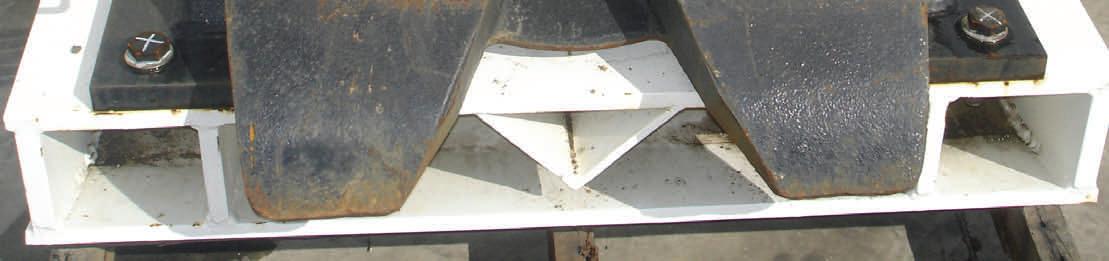
RAS Attach Hooks

RAS Lock Tongue Slot


Spade Lip Type Ejector Bucket Attachment
STRAIGHT LIP EJECTOR BUCKET
Various size ejector buckets are available, all with common operation and servicing requirements. Two double acting hydraulic cylinders actuated from the PTO lines on both sides of the lift arm assembly operate a hinged ejector plate for material discharge.
Specifications:
Unladen Mass: 3637 kg Capacity: 4.5 m3 Width: 2700 mm Height: 1533 mm Length: 2250 mm
Servicing
Every time the ejector bucket is to be attached to the machine a visual inspection should be carried out to ensure that the locking and retention components are in good condition.
1. Check the bucket RAS attach hooks for damage. 2. Check the RAS lock tongue slot for damage or excessive wear. 3. Check the bucket back plate welds for signs of cracking. 4. After the bucket has been attached to the machine check that the RAS lock tongue is fully engaged in the bucket lock tongue slot. 5. Disconnect the driver’s side PTO lines from the RAS lock tongue and connect to the push plate. 6. Extend and retract the push plate and check for free plate operation, cylinder pivot wear and hydraulic system leaks. 7. Grease the eject cylinder bottom pivot points.
RAS Attach Hooks

RAS Lock Tongue Slot
Straight Lip Type Ejector Bucket Attachment
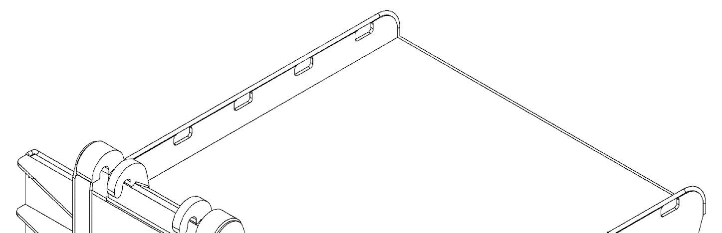
RAS EJECTOR BUCKET
The ejector plate tongue is actuated via the FBL’s control valves, the PTO hose on the driver’s side of the lift arm need to be disconnected from the RAS lock cylinder and connected to the ejector tongue cylinder hoses as shown in the picture below.
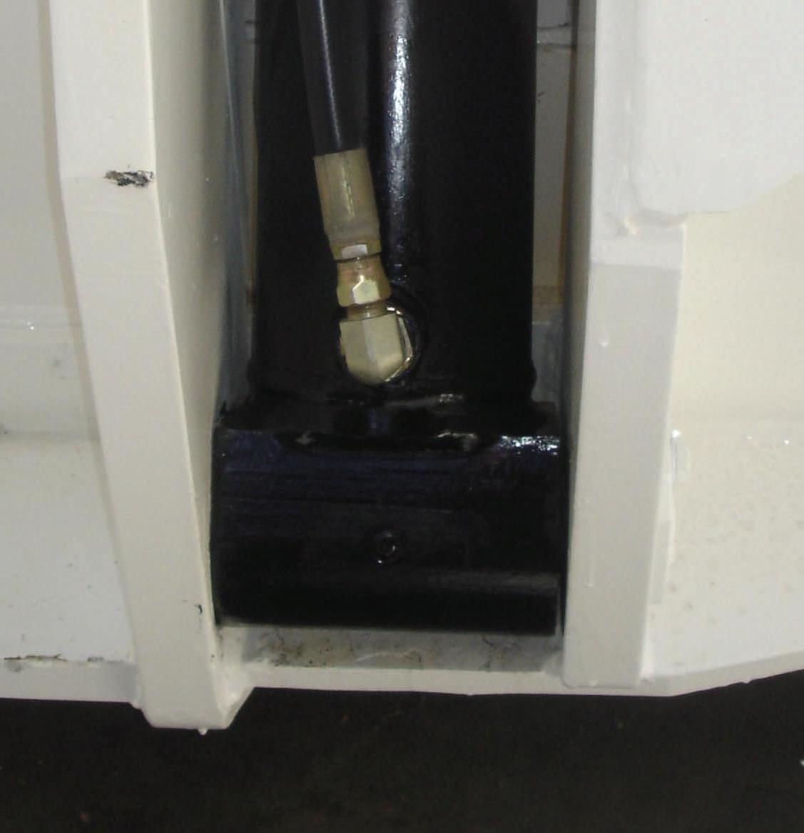
Ejector Bucket Hydraulic Cylinder Grease Point
10000 KG SIDE SHIFT FORKS
The side shift fork attachment is rated to carry 10000 kg at 600 mm from the fork tine face. The fork tines are fastened to the attach plate chassis via a top pin and bottom keeper. One double acting cylinder is located on each fork tine to enable independent side shift from the machine’s hydraulic PTO controls. Load chains are fastened to the attach plate chassis to support the carried load on the forks.
Specification
Unladen Mass: 2700 kg Width: 1980 mm Height: 1540 mm Length: 2290 mm Operating Grade (side to side): 1:8
Servicing
Every time the side shift forks are attached to the machine a visual inspection should be carried out to ensure that the locking and retention components are in good condition.
1. Check the fork assembly RAS attach hooks for damage. 2. Check the RAS lock tongue slot for damage or excessive wear. 3. Check the fork tine back plate welds for signs of cracking. 4. Check the fork tines for damage, particularly at the heel of the fork and the pin block at the top of the fork. 5. After the forks have been attached to the machine check that the RAS lock tongue is fully engaged in the RAS plate lock tongue slot. 6. Side shift both forks and check for free operation and hydraulic system leaks.
Do not use the fork attachment if defects are found. Report the faults immediately to a supervisor and have the fault repaired and verified before use.
Side Shift
Fork Tine Pin Block
Fork Tine Heel
10000 kg Side Shift Fork Attachment
7000 KG FIXED JIB CRANE
The fixed jib crane attachment is rated to carry 7000 kg on the extension arm and 12000 kg on the fixed jib. The jib crane is fitted with a 12000 kg rated clevis on the fixed section and is fitted with a 7000 kg rated lifting hook on the extendable section.
The extendable section of the jib is manually operated and allows an additional 500 mm longitudinal extension beyond the fixed arm.
Specification
Unladen Mass: 1680 kg Width: 1130 mm Height: 1290 mm Length: 3920 extended mm Operating Grade (side to side): 1:8
Servicing
Every time the fixed jib crane is attached to the machine a visual inspection should be carried out to ensure that the locking and retention components are in good condition.
1. Check the jib crane RAS attach hooks for damage. 2. Check the RAS lock tongue slot for damage or excessive wear. 3. Check the jib crane back plate and arm welds for signs of cracking. 4. Check the lifting clevis, lifting hook and associated lifting components for damage. 5. Check that the extension arm lock pin is secure. 6. Check that the RAS lock tongue is fully engaged in the RAS plate lock tongue slot.
Do not use the jib crane attachment if defects found with the structure or lifting components. Report the faults immediately to a supervisor and have the fault repaired and verified before use.
RAS Lock Tongue Slot
RAS Attach Hooks
Extension Arm Lock Pin
12000kg Lifting Clevis
10000 kg Fixed Jib Crane
7000kg Lifting Hook
7000kg SWL

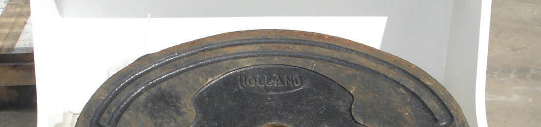
5TH WHEEL ADAPTOR
The roof support trailer tow point is specifically designed to attach the machine to a heavy load trailer such as one for transporting longwall roof supports.
The RAS attach plate is fitted with a 5th wheel mechanism for minimising component strain when hauling heavy loads.
The tow point is rated for a 65000 kg roof support trailer with a maximum vertical load of 15000 kg.
Specification
Unladen Mass: 1500 kg Width: 1180 mm Height: 1500 mm Length: 1100 mm Operating Grade (side to side): 1:8
Servicing
Every time the RAS tow point is used a visual inspection should be carried out to ensure that the locking and retention components are in good condition.
1. Check the tow point RAS attach hooks for damage. 2. Check the RAS lock tongue slot and 5th wheel centre for damage or excessive wear. 3. Check that the 5th wheel assembly fasteners are secure and check the 5th wheel assembly for signs of cracking or damage. 4. Check that the RAS lock tongue is fully engaged in the RAS plate lock tongue slot. 5. Check that 5th wheel assembly are free to rotate and release and lock function need to be tested.
Do not use 5th wheel attachment if defects found with the structure or towing components. Losing the trailer when operation could cause serious damage and personal injure. Report the faults immediately to a supervisor and have the fault repaired and verified before use.

5th Wheel Adaptor for FBL-10
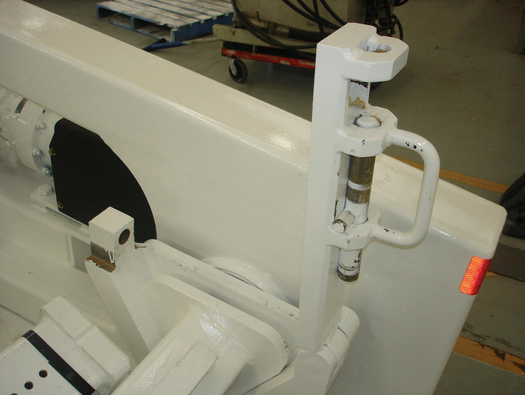
TURN TABLE RELEASE HANDLE
The locking and release of the CHT-50’s king pin to the 5th wheel mechanism is via the handle shown in the diagram below. Pulling the handle out will release the mechanism from the trailer kin pin while pushing the handle locks the mechanism.
Before attaching the 5th wheel to the CHT-50 the king pin must be checked for serviceability, if a fault is found it must be reported to maintenance personnel and rectified before returning to service.
Turn Table Release Handle

5th Wheel Adaptor Turn Table


CHT-50 King Pin
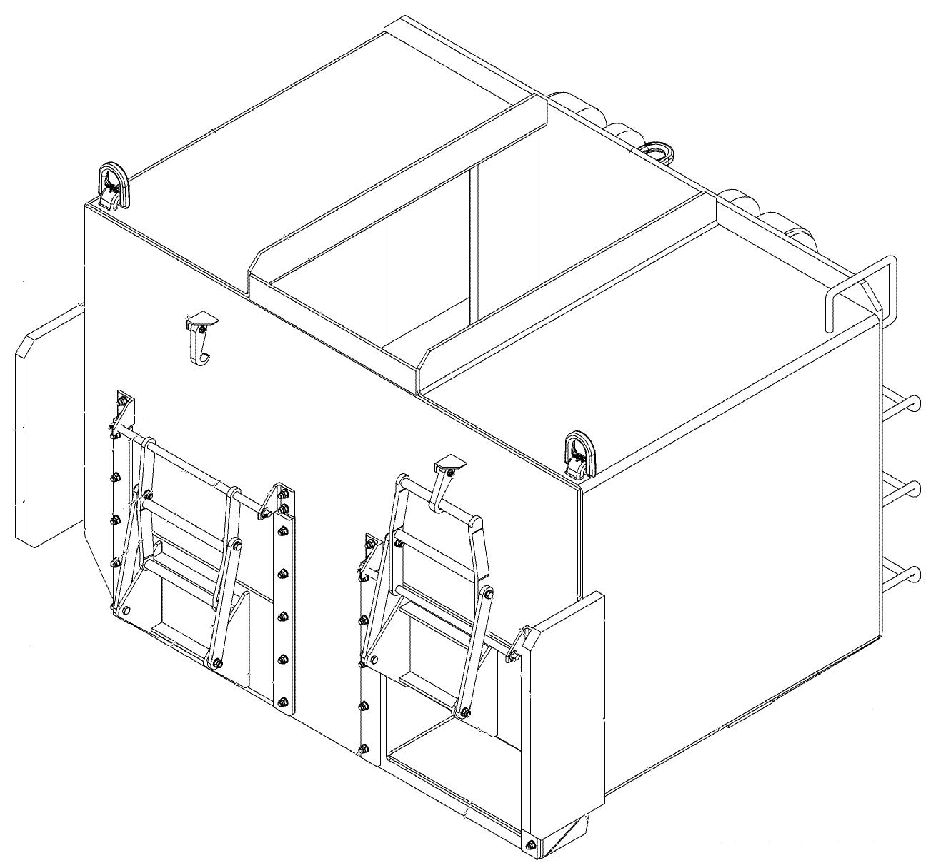
MATERIALS POD
The materials pod attachment is used to carry supplies and equipment with in the mines structure.
Specifications
Unladen mass: 3320 kg Length: 3477 mm Width: 2505 mm Height: 1410 mm Capacity (distributed evenly over four pallets): 6700 kg Operating Grade (side to side): 1:8
Servicing
Every time the materials pod is attached to the machine a visual inspection should be carried out to ensure that the components are in good condition.
1. Check the attachment RAS attach hooks for damage and wear. 2. Check the RAS lock tongue slot for damage or excessive wear. 3. Check the materials pod back plate and arm welds for signs of cracking or stress. 4. Check all components for damage, DO NOT use if damaged or faulty. 5. Check that the RAS lock tongue is fully engaged in the RAS plate lock tongue slot. 6. Slew the jib and check for free operation and hydraulic system leaks.
RAS Attach Hooks Tie Downs

RAS Lock Tongue Slot
This lifting device shall:
Only be used by trained and authorised operators. Not lift more than the rated laden safe working load. Not be operated on grades more than 1:8 (side to side) . Not to exceed the maximum laden tramming speed of 9 kph. Carry the loads as close as possible to the ground at all times.


Maximum load to be carried in the materials pod is 6700kg, the load is to be evenly distributed over four pallets as shown in diagram above.
Cut outs are to be used for tie down points only, not to be used for lifting or towing.
HYDRAULIC REELER
The hydraulic reeler is designed carry, feed or remove conveyor belt, AFC chain from structure and can be adapted to reel electrical cable for underground reticulation.
The machine supplies hydraulic power via the power take off lines and supplies a two speed hydraulic motor. Motor control is via a valve bank on the reeler chassis and provides speed and direction selection system prevents the maximum set tension from being exceeded.
Specifications
Capacities and Performance
Unladen mass of the belt reeler (approx) 2500 kg Maximum laden mass of the belt reeler (approx) 11500 kg Length of belt reeler (no belt on spool) 2080 mm Width of belt reeler 2640 mm Height of the belt reeler (no belt on spool) 1520 mm Maximum grade (front to rear) 1:4 Maximum grade (side to side) 1:8
Maximum diameter of the belt spool 2200 mm Maximum width belt 1600 mm Maximum mass of belt 9000 kg
Belt Thickness (mm) Reeler Capacity (m)
12 375
14 320
16 280
18 250
20 220
22 200
24 185
26 170
28 160
30 145
Hydraulic
Supply FBL-10 Engine operating speed Low idle (650 RPM) Operating pressure 13.79 MPa
Main pressure relief valve setting Oil type 14.48 MPa ISO 68 Hydraulic
Hydraulic Motor
Type
Planetary Gearbox
Type Mechanical rating (continuous) Mechanical rating (intermittent) Oil type (planetary) Capacity of the planetary
Bevel Gear Set
Two-speed hydraulic gear motor (pilot operated)
Three-stage planetary gearbox 13000 Nm 20000 Nm LS90 Gear Oil 2.5 litres
Oil Type
Spindle Bearings
Lubricant SAE90LS Gear Oil
Shell Alvania EP or equivalent
(Note: All specifications relate to the reeler only. Specifications may alter. Please contact Bucyrus if specifications are critical to safe operation).
This reeler produces a maximum torque of 28 kNM in at 3000 PSI motor speed 1800 RPM, ensure that:
1. During reeling operation ensure maximum allowable tension is not exceeded, for items being pulled refer to the colliery data or official for maximum allowable tension on items being pulled. 2. Ensure the spool is correctly locked in carrier. 3. Ensure items being reeled are correctly attached to the spool. 4. It is recommended to reel from the bottom of the reeler. 5. Check items being reeled, are free during reeling.
Servicing
Daily:
1. Check that all guards are in place. 2. Inspect the hydraulic system for loose or damaged components including condition of quick connect couplings. 3. Check the reeler RAS attach hooks for damage. 4. Check the RAS lock tongue slot for damage or excessive wear. 5. Check that the RAS lock tongue is fully engaged in the RAS plate lock tongue slot. 6. Inspect all frame components including spool coupler and lock plate. 7. Start and run the reeler and check that the reeler operates freely in forward, reverse, high and low speeds.
90° Bevel Gearbox
Spool Lock Pin
Shaft Coupling

Torque Hub Spool

Hydraulic Drive Motor
Reeler Main Parts
Drive Shaft Coupling Cover
DO NOT operate the attachment with damaged or missing covers, if covers are damaged or missing report to maintenance personnel.
DO NOT remove cover while the attachment is in operation, it must be isolated and tagged as per site tagging/locking procedures.
LOCKING THE SPOOL
The spool is locked into the reeler via two locking pins on each side, the locking pins slide into a hole securing the spool. A lynch pin is fitted through a hole in the locking pin to secure it and stop it retracting from the hole.
DO NOT operate the reeler with out the safety lynch pins fitted to the locking pins.
Locking Pin Hole
Spool Locking Bracket
Locking Pin
ELEVATED WORK PLATFORM
The elevating work platform is designed to be carried by the machine’s RAS attach system. The primary purpose for the platform design is for personnel to access the mine roof or elevated services and provide a safe working area for performing tasks when elevated above ground level.
The platform is fitted with operator controls for engine emergency stop.
Specifications
Maximum number of persons to be elevated: Tare mass of platform (approximate): Maximum load of platform: Platform length: Platform width: Total height: Maximum operating grade (front to rear): (side to side): 2 1900 kg 1500 kg 2540 mm 2180 mm 340 mm 1:4 1:8
Platform Raise/Lower and Tilt Adjustment
All raising, lowering and tilt adjustment are carried out from the operator’s compartment using the lift and tilt controls.
The platform is not intended for personnel riding. Do not transport personnel in the platform as serious injury may result. Always allow personnel to exit the platform from ground level before tramming the machine.
Emergency Stop
The emergency stop valve located on the platform’s plate closest to the RAS attach hooks. Once activated it stops the machine’s diesel engine. Once the engine has stopped hydraulic power is also isolated to the raise/lower and tilt functions.
Servicing
Daily:
1. Check the RAS attach hooks for damage. 2. Check the RAS lock tongue slot for damage or excessive wear. 3. Check that the platform access door latches are functional and the door swings freely. 4. Check that the RAS lock tongue is fully engaged in the RAS plate lock tongue slot. 5. Check that the platform deck and guard rails are free of damage and slip, trip and fall hazards. 6. Before introducing into service with attachment connected to the machine test the emergency stop valve. 7. Ensure all accessories are not damaged and in good working order.


Plan View of Work Platform

Spring Return Gate and Self Latching Catch
The work platform has a number of various attachments available for use, these attachments are to be fully maintained and kept in good working to the OEM’s specifications.
Corner Post Accessory Adjustments Cable and Pipe Handlers


Pipe Handler with Vice Assembly
CONCRETE HOPPER
The hopper is designed to be carried by the machine’s RAS attach system. The primary purpose is to transport concrete to various parts of the mine.
The concrete hopper is fitted with one access/fill section at the top and two delivery shutes fitted with manually operated gates.
Specifications
Tare mass of hopper (approximate): 4300 kg Maximum load (concrete): 9651kg (4 M³) Hopper length: 2094 mm Hopper width: 2430 mm Total height: 1700 mm Maximum vehicular inclination (front to rear): 1:4 Maximum vehicular inclination (side to side): 1:8
Platform Raise/Lower and Tilt Adjustment
All raising, lowering and tilt adjustment are carried out from the operator’s compartment using the lift and tilt controls.
This lifting device shall:
Only be used by trained and authorised operators. Not lift more than the rated laden safe working load. Not be operated on grades more than 1:8 (side to side) . Not to exceed the maximum laden tramming speed of 9 kph. Carry the loads as close as possible to the ground at all times.


FUEL POD
The fuel pod is designed to be carried by the machine’s RAS attach system. The primary purpose is the storage of fuel (diesel) for supplementary servicing underground.
The fuel pod is fitted with extendable hose reel for refueling, a pump unit powered by air and a fire suppression system manually of automatically activated.
Specifications
Weight: 5020 kg Length: 2500 mm Width: 2500 mm Height: 1500 mm
Fuel Pod Raise/Lower and Tilt Adjustment
All raising, lowering and tilt adjustment are carried out from the operator’s compartment using the lift and tilt controls.


Fuel Cell Bunded Area/ Jerry Can Holder

Manual Activation for Fire Suppression
Emergency Stop for Fuel Shut Off
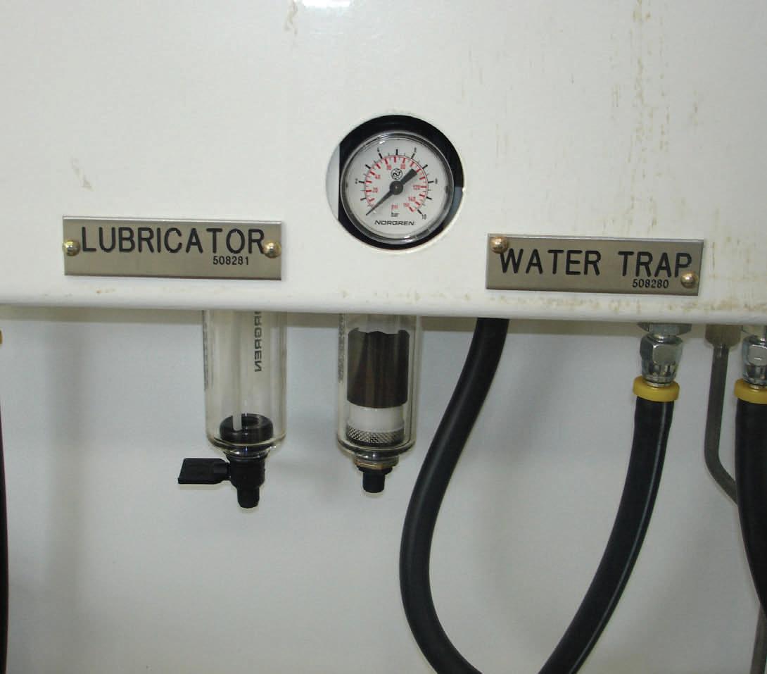
Air Pressure Gauge for Supply Air
Water Trap
Oil Lubrication

Supply Air Connection
Supply Air On/Off Valve

Fuel Hose and Nozzle

Fork Pocket Fuel Hose Reel Unit Air Pump for Fuel Delivery