5 minute read
Electrical system.................................................................5


Electrical system
The following pages contain a brief description of the major electrical components and assemblies that are on the feeder breaker.
The machine receives electrical power through a heavy-duty trailing cable. Be sure that the box connector is correctly identified and is securely connected; also check that the cable entrance is in good mechanical condition. Walk along the trailing cable from the power center to the feeder breaker and check the condition of the trailing cable. Give special attention to points most apt to cause damage, such as corners, intersections, and where cable may be run over by moving equipment. Never use trailing cable with exposed wires or splices which heat up or spark under load.
WARNING! This section is intended only to familiarize the user with the major electrical components of the feeder breaker. All electrical maintenance should be performed only by a qualified electrician with the knowledge of the function of the components involved.
WARNING! Before removing the cover from the starter enclosure and attempting any maintenance or troubleshooting on the machine, the main power must be disconnected and locked and tagged out at the main power center.
starter enclosure
panic strips
conveyor/breaker motor
high pressure switch
breaker shaft underspeed sensor
low oil switch
high temperature switch
The starter enclosure houses the machines electrical controls.
There are two panic strip located on the machine. Activating either panic strip will open the master control relay, “MCR”, thereby shutting down the machine.
The conveyor/breaker motor is a 200 HP, 950 VAC, 3 phase, 60 Hz, totally enclosed, fan cooled non-explosion proof electric motor.
The high pressure switch monitors the hydraulic pump suction pressure. If the pressure becomes too high, the switch will open, turning off both the “HIGH TEMP”and “HIGH PRESS”LEDs on the front of the electrical enclosure.
The breaker shaft underspeed sensor is mounted on the breaker shaft assembly and monitors the speed of the breaker shaft. If the breaker shaft speed falls below a preset value, the electric motor will shut off.
The low oil switch is mounted inside the oil tank. If the oil level in the tank falls below a preset value, the switch will open, turning off the “LOW OIL”, “HIGH PRESS”, and “HIGH TEMP”LEDs on the front of the electrical enclosure.
The high temperature switch is mounted on the wall behind the oil tank and the temperature probe is located in the oil tank. If the hydraulic oil temperature exceeds 165° F, the switch will open, turning off the “HIGH TEMP”LED on the front of the electrical enclosure.
Fig. 18: Starter enclosure Starter enclosure
The starter enclosure houses the primary electrical control components.
WARNING! Before removing the cover from the starter enclosure and attempting any maintenance or troubleshooting on the machine, the main power must be disconnected and locked and tagged out at the main power center.
There are operational controls located on the front of the starter enclosure (Fig. 18). For control descriptions, see the Controls and Indicators section in this chapter.
1 2 3 4 5 6 7
8 9 10 11 12 13
1. “15 AMP CB RESET” 2. “STOP” 3. “POWER ON”LED 4. “HIGH TEMP”LED 5. “LOW OIL”LED 6. “HIGH PRESS”LED 7. “CONV FWD/OFF/CONV REV” 8. “AUTO/OFF/MAN” 9. “E-STOP CONTROLLER” 10. “CONV/OFF/TRAM” 11. “START” 12. “CONV SPEED POT” 13. Circuit breaker reset lever
Swing panel - front side
The swing panel (Fig. 19) is accessed by opening the cover on the enclosure. Immediately adjacent to the swing panel is the main circuit breaker, CB1, for the feeder breaker.
Note that component locations are typical. Always consult the parts book for your machine to verify locations.
Fig. 19: Swing panel, front side
1 2 3 4 5 6 7 8 9

10 11 12 13 14 15 16 17 18 19 20 21 22 23
1. “POWER ON”LED 2. “HIGH TEMP”LED 3. “LOW OIL”LED 4. “HIGH PRESS”LED 5. TR 6. TR1 7. TR2 8. TR3 9. IS relay 10. BSCR 11. CRC 12. CRT 13. CRF 14. CRR 15. SR 16. MCR 17. R1 18. R2 19. RR 20. CONVERTER 2 21. CONVERTER 3 22. Amplifier card 1 23. Amplifier card 2
The “POWER ON”LED is used to indicate the status of the power to the machine.
The “HIGH TEMP”LED is used to indicate the hydraulic oil temperature status.
The “LOW OIL”LED is used to indicate the status of the hydraulic oil level in the tank.
The “HIGH PRESS”LED is used to indicate suction pressure status at the hydraulic pump.
TR is the timer for the high temperature sensor.
TR1 is the timer for the breaker underspeed switch.
TR2 is the override timer for TR1 on start-up.
TR3 is the timer for the conveyor.
The IS relay is the intrinsically safe relay for the panic strips.
BSCR is the belt sequence switch control relay.
CRC is the conveyor mode of operation control relay.
CRT is the tram mode of operation control relay.
CRF is the conveyor forward relay.
CRR is the conveyor reverse relay.
SR is the safety relay for the panic strips.
MCR is the master control relay. This relay receives input from the two panic strips and the emergency stop button .
R1 is the relay for “AUTO”mode of operation.
R2 is the relay for “MANUAL”mode of operation.
RR is the relay to reset timer TR3.
CONVERTER 2 is the power supply for the conveyor and tram mode of operation solenoids.
CONVERTER 3 is the power supply for the conveyor forward and reverse mode of operation solenoids.
The electronic amplifier boards, AMPLIFIER CARD 1 and CARD 2, drive the conveyor speed solenoids located on the valve bank.
“POWER ON”LED
“HIGH TEMP”LED
“LOW OIL”LED
“HIGH PRESS”LED
TR
TR1
TR2
TR3
IS relay
BSCR
CRC
CRT
CRF
CRR
SR
MCR
R1
R2
RR
CONVERTER 2
CONVERTER 3
AMPLIFIER CARD 1 and CARD 2
“T1”
“M1”
“OL1” Back panel
The back panel (Fig. 20) is accessed by removing the swing panel retaining bolt located in the upper left hand corner of the swing panel and swinging the panel out. Note that component locations are typical. Always consult the parts book for your machine to verify locations.
Fig. 20: Back panel, typical
Control transformer, T1 Vacuum contactor, M1
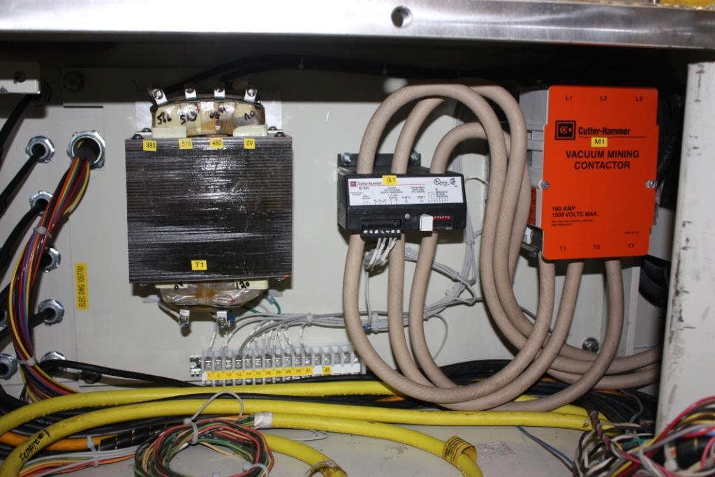
Overload, OL1
“T1”is the control transformer that reduces the voltage to the control circuit from 950V to 120V.
“M1”if the vacuum contactor for the motor.
“OL1”is the overload relay for the motor. If the motor is overloaded, the relay will shutdown the motor.