9 minute read
Electrical system.................................................................5


BI016382
Electrical system
The following pages contain a brief description of the major electrical components and assemblies that are on the feeder breaker.
The machine receives electrical power through a heavy-duty trailing cable. Be sure that the box connector is correctly identified and is securely connected; also check that the cable entrance is in good mechanical condition. Walk along the trailing cable from the power center to the feeder breaker and check the condition of the trailing cable. Give special attention to points most apt to cause damage, such as corners, intersections, and where cable may be run over by moving equipment. Never use trailing cable with exposed wires or splices which heat up or spark under load.
WARNING! This section is intended only to familiarize the user with the major electrical components of the feeder breaker. All electrical maintenance should be performed only by a qualified electrician with the knowledge of the function of the components involved.
WARNING! Before removing the cover from the starter enclosure and attempting any maintenance or troubleshooting on the machine, the main power must be disconnected and locked and tagged out at the main power center.
BI016382
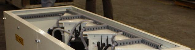
Fig. 25: Major electrical component locator
Head shaft tachometer
Belt pulley underspeed sensor
Panic strip
Breaker power unit
Photo eye board enclosure
Trailing cable junction box
Starter enclosure Oil temperature probe
Suction transducer
High temperature
Conveyor power unit
Oil level float and switch
Panic strip
Breaker shaft underspeed sensor and tachometer
Shuttle car power distribution enclosure
Panic strip
Pressure transducer
Photo eye sensor Emergency pull cord
Photo eye sensor
BI016382
belt pulley underspeed sensor
breaker shaft underspeed sensor
panic strips
emergency pull cord
photo eye sensors
high temperature switch
low oil switch
breaker power unit
conveyor power unit
The belt pulley underspeed sensor in mounted on tailpiece on the right hand side of the machine, near the pulley. The sensor will shut down the conveyor electric motor if the conveyor stops running.
The breaker shaft underspeed sensor is mounted on the breaker shaft assembly and monitors the speed of the breaker shaft. If the breaker shaft speed falls below a preset value, the electric motors will shut off.
There are three panic strips located on the machine. Activating any one of the panic strips will open the master control relay, “MCR”, thereby shutting down the machine.
Activating the emergency pull cord, located over the hopper, will open the master control relay, “MCR”, thereby shutting down the machine.
The photo eye sensors are used to remotely start the conveyor/pump motor and are mounted on top of the machine on both sides of the hopper. The pump motor will start when a light shines on the sensor for approximately four seconds.
The high temperature switch is mounted on the wall behind the conveyor power unit on the right hand side of the machine and will shut down the machine if the hydraulic oil temperature exceeds a preset value. The temperature probe is located in the oil tank.
The low oil switch is mounted inside the oil tank. The electric motors will shut off if the oil level in the tank falls below a preset value.
The breaker power unit is a 200 HP, 950 VAC, 3 phase, 60 Hz, 1750 rpm, totally enclosed, fan cooled non-explosion proof electric motor.
The conveyor power unit is a 125 HP, 950 VAC, 3 phase, 60 Hz, 1750 rpm, totally enclosed, fan cooled non-explosion proof electric motor.
BI016382
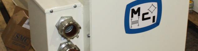
Fig. 26: Trailing cable junction box Trailing cable junction box
The trailing cable junction box (Fig. 26) is located on the right side of the machine. From the trailing cable junction box, power is sent to a junction box on the shuttle car distribution enclosure. There is an “EMERGENCY STOP”button located on the trailing cable junction box. When activated, the “EMERGENCY STOP”but will shut the machine down by disconnection the pilot in the incoming trailing cable. If the “EMERGENCY STOP”button is activated, the power must be reset at the main power center.
Connection to shuttle car distribution box (not shown)
“EMERGENCY STOP”(optional)
Trailing cable connection
BI016382
Shuttle car distribution box
The shuttle car distribution box (Fig. 27) is located on the right side of the machine. Power enters the distribution box from the trailing cable junction box and is distributed to the starter enclosure and three shuttle car power circuits.
Fig. 27: Shuttle car distribution box (typical)
Ground fault monitor (3) Circuit breaker “ON/OFF” (3)
“EMERGENCY STOP”button
“120 VOLTS CONTROL FUSE
120V GFCI receptacle
“CIRCUIT #1” shuttle car cable receptacle “CIRCUIT #2” shuttle car cable receptacle “CIRCUIT #3” shuttle car cable receptacle 120V receptacle circuit breaker
Incoming power cable connection
Outgoing power cable connection to starter enclosure


BI016382
Fig. 27, continued: Shuttle car distribution box
Ground fault monitor (3) Circuit breaker (3)
Fuse (2) (10A 120V) 950 - 120VAC transformer
Bus bar (3)
BI016382
ground fault monitor
“EMERGENCY STOP”
“120 VOLTS CONTROL FUSE”
circuit breakers
120V GFCI receptacle and circuit breaker
A ground fault monitor is located in each 995V circuit. The ground fault monitors for ground fault leakage current in the circuit. If a ground fault is connected, the circuit will trip, removing power from that circuit. There is a ground test function for each ground fault monitor
When activated, the “EMERGENCY STOP” button will trip the pilot in the trailing cable. If the “EMERGENCY STOP”is activated, all power is removed from the machine and must be reset at the power center.
The “120 VOLTS CONTROL FUSE”is connected to both the 120V and the 995V circuits. If this fuse is blown, the 995V circuit breakers cannot be set (turned on).
A thermal-magnetic trip 225A circuit breaker with a trip range of 300 to 650A and 120V UVR (under voltage release) is located in each of the three 995V circuits. Turning the circuit breaker to the “ON”position will energize the shuttle car receptacle. Do not turn the circuit breaker to the “ON”position if the 120V fuse is blown.
CAUTION! Do not set the circuit breaker if the 120V fuse is blown. Internal damage to the circuit may occur.
The 120V GFCI (ground fault circuit interrupter) outlet is located on the right side of the box. The 120V receptacle is energized by setting the single pole, 15A circuit breaker located below the receptacle.
BI016382
Fig. 28: Starter enclosure Starter enclosure (54-2185)
The starter enclosure, located on the right side of the machine, houses the primary electrical control components.
WARNING! Before removing the cover from the starter enclosure and attempting any maintenance or troubleshooting on the machine, the main power must be disconnected and locked and tagged out at the main power center.
There are operational controls located on the front of the starter enclosure (Fig. 28). For control descriptions, see the Controls and Indicators section in this chapter.
“MAN/OFF/ AUTO” “TRAM/OFF/ CONV” “FWD/OFF/ REV” “LIGHTS ON/OFF” PLC controls and display panel
“15 AMP CB RESET “ACKNOWLEDGE ALARMS” “START BREAKER” “START CONV/PUMP” “PICK BRK/ CONV STOP” “E. STOP” Circuit breaker reset lever
circuit breaker
In addition to the switches and the display panel, there is a 15A circuit breaker for control power mounted on the back side of the cover panel.
BI016382
Fig. 29: Swing panel (typical) Swing panel
The swing panel (Fig. 29) is accessed by opening the cover on the enclosure. Located on the swing panel are: indicator lights, relays, timers, and a circuit breaker reset.
Immediately adjacent to the swing panel is the main circuit breaker, CB1, for the feeder breaker.
Note that component locations are typical. Always consult the parts book for your machine to verify locations.
PLC power supply Analog input module Analog input module Analog output module Digital input module Digital input module Digital output module Amplifier board #1 Amplifier board #2 IS relay
Resistor Power supply 1 Power supply 2 Power supply 3 “SR” “MCR” “CRWS” “CR1” “CR2” “CRR” Current transducer TAC monitor TAC monitor Fuse, 10A Fuse, 10A
BI016382
PLC power supply The PLC power supply provides power for the PLC control system.
analog input modules
analog output module
amplifier boards
digital input modules
digital output modules
IS relay
TAC monitors
current transducer
“SR”
“MCR”
“CRWS”
“CR1”
“CR2”
“CRR”
resistor
fuses
There are two analog input modules that receive inputs from the current transducers.
The analog output module sends a signal to the amplifier boards.
The electronic amplifier boards drive the conveyor speed solenoids.
There are two digital input modules that communicate the positions of the selector switches, sequence switch, and auxiliary contactors to the PLC.
The digital out module communicates with the coils and relays based upon input to the two digital input modules.
The IS relay is the intrinsically safe relay for the three tape switches (panic strips).
The TAC monitors pickup the conveyor shaft and pick break speeds and send a signal to the PLC.
The current transducer monitors the pick break motor amps.
There are six relays located on the panel:
“SR”is the safety relay for the tape switches (panic strips).
“MCR”is the master control relay.
“CRWS”is the water solenoid relay.
“CR1”is the conveyor forward relay.
“CR2”is the tram relay.
“CRR”is the conveyor reverse relay.
The 33 KΩ, 1/2W resistor works in conjunction with the safety relay, “SR”to close the circuit so the machine can be started.
The two 10A fuses are for the lighting circuit. Once fuse is for the hot side and one is for the neutral side.
BI016382
Fig. 30: Back panel, typical
“T1”
Back panel
The back panel (Fig. 30) is accessed by removing the swing panel retaining bolt located in the upper left hand corner of the swing panel and swinging the panel out.
Note that component locations are typical. Always consult the parts book for your machine to verify locations.
“T1”is the control transformer that reduces the voltage to the control circuit from 950V to 120V.
“M1”if the vacuum contactor for the pick break motor.
“F1”is the vacuum contactor for the conveyor/pump motor.
“OL1”is the overload relay for the pick break motor. If the pick break motor is overloaded, the relay will shutdown the motor.
“OL2”is the overload relay for the conveyor/pump motor. If the conveyor/pump motor is overloaded, the relay will shutdown the motor.
Vacuum contactor, “F1” Current transducer (6) Vacuum contactor, “M1”
Current transformer
Fuse 2) Voltage transducer
“T1”
“M1”
“F1”
“OL1”
“OL2”
“OL2” “OL1”
BI016382
current transducers
voltage transducer
fuse
There are six current transducers on this panel. The first three monitor each phase of the power to the pick break motor and the next three monitor each phase of the conveyor/pump motor. The current draw for each phase is displayed on the display panel on the front of the starter enclosure.
Starting at the top, the transducers are:
#1 = Phase A, pick break motor #2 = Phase B, pick break motor #3 = Phase C, pick break motor
#4 = Phase A, conveyor/pump motor #5 = Phase B, conveyor/pump motor #6 = Phase C, conveyor/pump motor
The voltage transducer monitors and the control voltage, which is displayed on the display panel on the front of the starter enclosure.
The 5A fuse is for the power supply for the display panel.