
9 minute read
MACHINE OVERVIEW


SAFETY
The safety alert symbols displayed here and throughout this manual, are used to call attention to instructions concerning personal safety. Carefully read and follow these instructions and observe all SAFETY, DANGER and CAUTION graphics mounted on various areas of the machine.
Be certain anyone servicing this machine is aware of these SAFETY SYMBOLS and their definitions. If it is impossible to safely perform any of the enclosed maintenance and operational procedures, contact your regional Bucyrus service representative or the factory.
The following defines distinctions between safety instructions. In all these definitions the safety alert signal is used.
NOTE: This signal word denotes an item of required information pertaining to the equipment. A loss of time, assets, or minor injury may result if the appropriate action is not taken.
CAUTION: This signal word serves as a reminder of safety practices, or directs attention to specific safety practices which could prevent possible injury if precautions are not adhered to.
DANGER: This signal word denotes an imminently dangerous hazard which will result in death, serious bodily injury, or serious damage to equipment if not acknowledged and appropriate action taken.
DANGER: This signal word denotes an imminently dangerous electrical hazard which will result in death, serious bodily injury, or serious damage to equipment if not acknowledged and appropriate action taken.
Operating, maintaining or servicing this machine is dangerous unless performed properly. Each person must satisfy himself and his employer that he is alert, has the necessary skills, knowledge, proper tools and equipment for the task at hand. It is critical that all the methods used are safe and correct. Factory service representatives and specialists are available to provide additional information or technical assistance. The operator must be alert, physically fit and free from the influence of alcohol, drugs, or any medications that might impair his eyesight, hearing or reactions.
CAUTION: STORED ENERGY! Components on machine are heavy and removal of pins without proper preparation and precaution can cause serious bodily injury and/or damage to the front-end of the machine.
Safety must always be paramount!
Consult your supervisor when safety is in doubt.
SAFETY PRECAUTIONS
General Precautions:
•The employment of qualified maintenance personnel, through a scheduled maintenance program, is the best way to minimize machine downtime and maximize productivity of equipment. •Keep hands, feet, and clothing away from rotating parts. •Wear a hard hat, safety shoes and protective lenses at all times. •Replace any and all safety and warning placards if they are defaced or removed from the machine.
•Think before you act. Carelessness is one luxury the service man cannot afford. •Excessive or repeated skin contact with sealants or solvents may cause skin irritation. In case of skin contact refer to the Material Safety Data Sheet (MSDS) for that material and the suggested method of cleanup. •Inspect safety catches (keepers) on all hoist hooks. Do not take a chance, the load could slip off of the hook if they are not functioning properly. •If a heavy item begins to fall, let it fall, don’t try to catch it. •Keep your work area organized and clean. Wipe up oil or spills of any kind immediately. Keep tools and parts off of the ground. Eliminate the possibility of a fall, slipping or tripping. •Floors, walkways and stairways must be clean and dry. After fluid draining operations be sure all spillage is cleaned up. •Electrical cords and wet metal floors make a dangerous combination. •Regularly inspect for any loose bolts or locking devices and properly secure them. •Use extreme caution while working near any electrical lines or equipment whether it be high or low voltage. Never attempt electrical repairs unless you are qualified. •Check limit switches for proper operation. •After servicing, be sure all tools, parts or servicing equipment are removed from the machine and secured in an appropriate storage area. •Mechanical Brakes are designed for use as static holding brakes only. Use as a motion (dynamic) brake in emergency situations only. •Use proper interior and exterior lighting. •Install and maintain proper grounding and ground fault protection systems. •Perform functional tests of all safety circuits. •Allow electrical inspection and maintenance to be performed only by a qualified electrician.
Maintenance Precautions:
•Do not wear rings, wrist watches or loose fitting clothing when working on machinery. They could get caught on moving parts causing serious injury. •Always wear a safety belt or harness when the danger of falling exists. •Always have a second person to monitor the lifeline when working in confined spaces. •Do not start an engine indoors unless adequate exhaust ventilators are provided and in operation. •Never utilize the machine air or hydraulic systems for support when working on the machine.
Deactivate or isolate the entire system prior to performing maintenance. •Equipment should be parked on level ground at all times during machine servicing and periods of idleness.
•Cranes and hoists must be of sufficient capacity to lift heavier components (gearcases, etc.)
Always work within the limitations of the equipment being utilized. •Be sure heavy items are properly rigged and supported from cranes or hoists before removing supporting members from the machine. •Utilize guide lines or ropes to minimize the swing of suspended heavy components. •Have sufficient service personnel available when removing or installing large heavy items to maintain control at all times.
•Always use safety stands in conjunction with hydraulic jacks or hoists. Do not rely on the jack or hoist to carry the load, they could fail. •When disassembling a machine, be sure to use safety stands and adequate cribbing to prevent tipping or rollover of components. •When using an oxy/acetylene torch, always wear welding goggles and gloves. Keep a charged fire extinguisher within reach. Be sure the acetylene and oxygen tanks are separated by a metal shield and are chained to the cart.
•Use pullers to remove bearings, bushings, gears, cylinder sleeves, etc. when applicable. Use hammers, punches and chisels only when absolutely necessary. Always be sure to wear safety glasses. •Use extreme caution when using compressed air to dry parts. Use approved air blowguns, do not exceed 30 PSI (207 kPa), wear safety glasses or goggles and use proper shielding to protect everyone in the work area. •Be sure to promptly reinstall safety devices, guards or shields after adjusting and/or servicing the machine.
•Protective eye goggles should be worn at all times when working on the air conditioning system.
Work on the air conditioning system only in a well ventilated area.
•Wipe away excess lubricants around bearings and gears. Never lubricate parts in motion. •Always wear approved rubber gloves, and use insulated hooks or tongs when handling a trail cable.
Operating Precautions:
•Wear hearing protection when exposed to the following noise levels in excess of the period indicated: 8 hours at 90 dBa 4 hours at 95 dBa 2 hours at 100 dBa 1 hour at 105 dBa 30 minutes at 110 dBa 15 minutes at 115 dBa •When in doubt about the noise level, wear approved hearing protection. •Do not attempt to get on or off the machine while it is in operation. Notify the operator prior to any attempt to board/exit the machine. •Do not move or operate the machine without first knowing the location and purpose of all personnel, test or support equipment, on or near the machine. •Do not allow unauthorized personnel on board the machine while in operation. •Use audible signals to warn of machine movements. A signal horn button is provided for this purpose. •Do not propel until the travel route has been cleared of obstructions. • Do not propel the machine on a slope greater than specified in the GROUND
PREPARATION section of the Operators Manual for this machine. •Prevent the trail cable from being dragged on the ground for long distances or at high speeds. •Limit the amount of cable being dragged by the machine. Pulling too much cable will damage both the cable and the machine.
MACHINE OVERVIEW
The following diagram identifies major components of the Dragline. The following are the four major areas of this machine:
• Base Frame
• Rotating Deck • External Structures
• Bucket and Boom
Nomenclature
The Base Frame or Tub as it is more commonly known, provides a stable platform on which rests the machinery house and external structures of this machine. In addition to its function as a platform, the Base Frame also provides the pivot point about which the entire dragline upper structures revolve.
Base Frame (Tub)
Rotation of the machinery house occurs as the gear packages of the swing motor assemblies engage a 360º circular segmented rack gear assembly.
Rotating Gear and Rails (Section View)
During rotation, the machinery house rides on a package of 138 rollers arranged to evenly spread the load over the upper and lower rail segments.
Roller Circle (Section View)
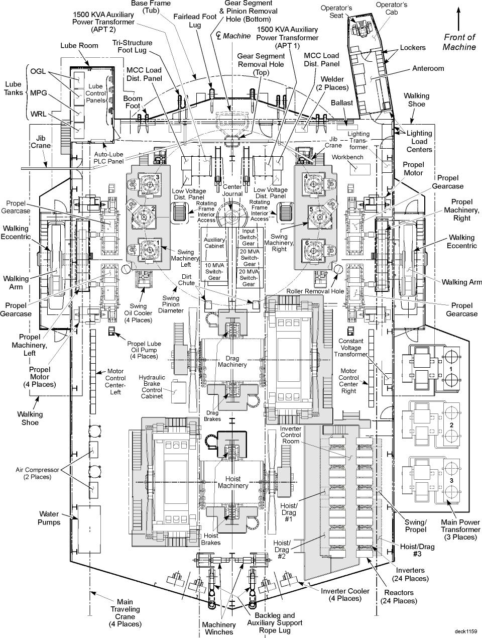
Deck Plan
Within the machinery house are the main powered elements of this machine. This includes Hoist and Drag motors and drums, Swing machinery, consisting of six separate motors and gear packages, plus the Propel machinery including four separate motors plus gear and walking assemblies.
Machinery House
The Operator’s Cab and Anteroom extend out from the front of the machinery house on the right hand side of the machine. The operators cab has glass on the front, left, and right hand sides allowing the operator to see the work area clearly and safely.
Operator’s Cab and Anteroom
The Operators seat is positioned at the front of the operators cab providing the best location to view the work of the machine. Controls for the machine are located on the two armrests of the machine. Joystick assemblies are provided to control machine positioning functions.
Moving the RIGHT joystick forward and backward controls the height of the bucket (Hoist functions). Moving the RIGHT joystick from side to side controls the rotation of the machine on the base frame. Moving the LEFT joystick forward and backward controls the distance of the bucket from the front of the machine.
In addition, setting a selector switch also allows the LEFT joystick to control the machine propel motion. Pulling back on the LEFT joystick, with the selector switch set, initiates the propel or backwards motion of the machine, while pushing forward repositions the shoe for the next propel motion.
Operator’s Seat and Controls
Note: Operators Control Console shown mounted to left arm. Console may be mounted on either arm as needed.
The propel machinery consists of four motors (two per arm), a gear package, a power transfer assembly, and the walking eccentric, arm and shoe. To move, the walking dragline physically lifts the back of the base frame (tub) off the ground, and drags the frame backwards.
Propel Machinery (Right Hand Shown, Left Opposite)
The hoist and drag machinery control motion of the draglines bucket. The Hoist Ropes go up the Boom of the machine and are used to raise and lower the bucket. The Drag Ropes control the relative distance of the bucket from the front of the machine. Different combinations of tension control the relative distance, depth and height to which the bucket is positioned.
Hoist and Drag Machinery
