304 minute read
TYPICAL MACHINE SPECIFICATIONS


COMPONENT WEIGHTS
Weight Ea. Qty. (Lbs.) BASE FRAME ASSEMBLY (Tub) ...........................................................948,400 Center Section...................................................................1...................102,350 Intermediate Inner Section .................................................2.....................51,100 Intermediate Outer Section................................................2.....................22,030 Rail/Gear Segment Section...............................................5.....................58,150 Base Frame Outer Section (typ.)......................................7.....................42,960 Base Frame Outer Sect, Elec...........................................1.....................43,070 Center Journal Pin.............................................................1.......................8,600 Roller Circle Assembly......................................................1.....................58,550 Roller ...............................................................................143........................330 Rail Segment (typ.)...........................................................24......................2,300 Gear Segment (typ.).........................................................18......................6,300 Thrust Rail Segment (typ.)................................................24.........................170 ROTATING FRAME ASSEMBLY ......................................................... 1,820,300 Hook Shoe .........................................................................2.....................13,150 Main Collector Rings..........................................................1.......................3,180 House Rear Door Assembly..............................................4.....................19,500 Air Filter..............................................................................5.......................6,820 Air Cleaner, Filter............................................................5..........................300 M.G. Set.............................................................................2...................172,800 Air Compressor.................................................................1.......................1,200 Deck Winch.......................................................................2.......................2,050 Auxiliary Transformer .........................................................1.....................12,600 Lighting Transformer..........................................................1..........................750 Switch Panel Board, Main..................................................1..........................600 Motor Control Center.........................................................1.......................5,000 Air Conditioner / Heater (Cab)............................................1..........................900 Generator...........................................................................1.......................8,950 Water Tank.........................................................................1..........................800 Ballast................................................................................1...................690,000
ROTATING MACHINERY
Rotating Gearcase Assembly............................................4.....................22,000 Main Rotating Shaft............................................................4.......................9,450 Pinion, Main Rotating .........................................................4.......................2,300 Coupling, Swing.................................................................4..........................425 Rotating Motor....................................................................4.....................15,700 Motor Brake, Swing............................................................4.......................1,450
Weight Ea. Qty. (Lbs.)
HOIST/DRAG MACHINERY
Hoist/Drag Gearcase Assembly........................................2...................118,500 Gearcase Structure, 4-Motor.............................................2.....................63,900 Gearcase Cover................................................................4.......................2,900 Hoist/Drag Drum Shaft Assembly......................................2...................153,000 Hoist/Drag Drum Gear.......................................................2.....................30,950 Drum Lagging....................................................................4.....................37,260 Drum End, Hoist/Drag.......................................................4.....................31,700 Bearing Housing, Intmd. Shaft...........................................4.......................3,130 Bearing Housing, Drum Shaft............................................4.......................5,160 Intermediate Pinion ............................................................4.......................5,000 Intermediate Shaft..............................................................4.......................8,860 First Intermediate Gear......................................................4.......................6,250 Motor Extension Shaft........................................................8..........................500 Gear Guard........................................................................2.......................1,000 Hoist/Drag Motor................................................................8.....................15,700 Motor Brake, Hoist/Drag.....................................................8.......................1,200
PROPEL MACHINERY
Walking Shoe.....................................................................2...................183,950 Walking Arm.......................................................................2.....................72,100 Stabilizer Link.....................................................................2.......................8,310 Pin, Arm to Stabilizer..........................................................2.......................5,350 Pin, Stabilizer to Frame.....................................................2.......................8,320 Shaft, Walking Shoe..........................................................2.......................6,560 Main Propel Shaft...............................................................2.....................32,530 Main Propel Gear ...............................................................2..................... 48,110 Gear Hub ...........................................................................2.....................12,530 Cam, Eccentric, Walking...................................................2.....................42,830 Main Propel Pinion Shaft Assembly...................................2.......................8,450 Main Propel Pinion Shaft....................................................2.......................5,000 Propel Gearcase................................................................2.....................42,360 Gearcase Structure...........................................................2.....................20,170 Gearcase Cover................................................................2.......................6,620 1st Intermediate Gear........................................................2.......................3,700 1st Intermediate Shaft........................................................2.......................1,630 2nd Intermediate Gear .......................................................2.....................11,460 2nd Intermediate Shaft.......................................................2.......................4,700 Motor Extension Shaft........................................................2..........................400 Propel Motor ......................................................................2.....................15,700 Motor Brake, Propel...........................................................2.......................1,200
Weight Ea. Qty. (Lbs.) FAIRLEAD ASSEMBLY.....................................................1...................306,020 Fairlead Structure..............................................................1...................151,100 Pin, Fairlead Foot...........................................................2..........................900 Backleg, Fairlead...............................................................2.......................9,000 Pin, Backleg, Upper.......................................................2.......................1,000 Pin, Backleg, Lower.......................................................2..........................410 Swivel Sheave Assembly, Lower.......................................2.....................42,300 Swivel Frame Assembly, Lower.........................................2.....................24,700 Swivel Frame.................................................................2.....................24,050 Shaft, Lower Swivel.......................................................2.......................3,700 Pin, Swivel Frame..........................................................4.......................1,050 Swivel Sheave Assembly, Upper.......................................2.....................18,750 Sheave, Fairlead Upper/Lower......................................4.....................12,150 Shaft, Upper Sheave Assembly.....................................2.......................4,900 Snubber, Lower Fairlead....................................................2..........................300 Snubber Collar Plate, Fairlead...........................................4..........................270 TRI-STRUCTURE ASSEMBLY ..............................................................573,350 Structure Assembly............................................................1...................355,380 Backleg..............................................................................2.....................70,900 Hoist Deflecting Sheave Assembly....................................2.....................18,150 Backleg Safety Rope.........................................................2.......................8,390 Boom Raising Sheave Assembly......................................4.......................6,330
BOOM ASSEMBLY (Less Walkways)
Boom Structure..................................................................1...................580,400 Boom Structure, Point.......................................................1.....................68,730 Boom Structure, Center.....................................................1...................395,650 Boom Structure, Foot-Left/Right........................................2..................... 30,520 Boom Point Sheave Assembly..........................................1.....................51,120 Boom Point Shaft...........................................................1.......................5,680 Boom Point Sheave.......................................................2.....................12,150 Trunnion, Boom Point Sheave...........................................1.....................11,600 Bearing Block, Trunnion - Rear......................................1.......................4,440 Bearing Block, Trunnion - Front.....................................1.......................1,400 Boom Support Rope Assembly.........................................2.....................38,770 Boom Support Rope Pendant............................................4.....................10,000 Intermediate Suspension Pendant.....................................2.......................2,120 Intermediate Suspension Adjuster.....................................2.......................2,350 Hoist Rope.........................................................................2.....................24,720 Guard, Hoist Rope, Boom point.........................................1..........................730 Drag Rope.........................................................................2.....................17,180
TYPICAL MACHINE SPECIFICATIONS
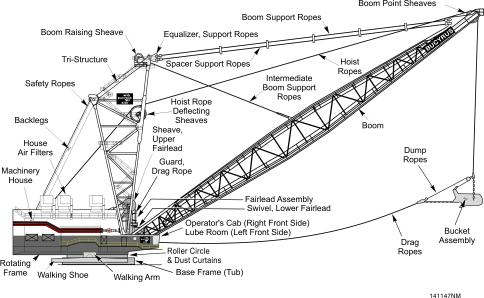
This specification describes the principal mechanical features of a standard Bucyrus International, Inc. 8200 Walking Dragline. NOTE: THESE ARE TYPICAL MACHINE SPECIFICATIONS.
WORKING RANGES
Boom Length ································································································ 355'-0" @ 34.25o ······························· 102.1 M Boom Point Sheave, Pitch Diameter················································································· 120" ················3353 cm A Boom Angle, Approx.····························································································34.25o ···································· 34.25o B Dumping Radius ··································································································· 287'-0" ····················87.5 M C Dumping Height ···································································································· 167'-0" ····················50.9 M D Depth ···················································································································· 197'-0" ····················60.0 M
Maximum Allowable Load ··············································································385,000 lb. ···········249,425 kg.
Hoist Drum, Pitch Diameter······················································································· 100" ················3048 mm
Hoist Ropes, Twin, Single Hitch, Diameter····························································· 4.00" ···············111.1 mm
Drag Drum, Pitch Diameter······················································································· 100" ················3048 mm
Drag Ropes, Twin, Single Hitch, Diameter······························································ 4.00" ···············111.1 mm
BASE
E Outside Diameter, Nominal ····················································································· 67’-0" ····················20.9 M
Bearing Area, Effective ······················································································3685 ft2 ····························· 342.3 m2
Bearing Pressure ······························································································· 19.0 PSI ········1.34 Kgs./cm2
Rail Circle, Mean Diameter····················································································· 50'-0" ····················15.2 M
Circle Rollers, Mean Diameter····················································································12"·················30.5 cm
Main Swing Gear, Pitch Diameter, Approx.···························································· 40'-5" ·················12.32 M
WALKING TRACTION
F Width of Shoe········································································································ 13'-0" ·························4.0 G Length of Shoe······································································································ 70'-0" ······················· 21.3 H Width over Both Shoes·························································································· 97'-0" ······················· 29.6
Bearing Area of Both Shoes·············································································· 1820 ft2 ····························· 169.1 M2
Bearing Pressure @ 80% of Working Weight··················································· 30.8 PSI ········2.17 Kgs./cm2
Length of Step, Approx.··························································································· 7'-6" ······················2.3 M
ROTATING FRAME
J Width @ Rear End································································································· 77'-4" ····················23.6 M K Length ·················································································································· 101'-0" ····················30.8 M
Depth Sill Members·································································································· 106" ·············2629.4 cm L Clearance Radius, Rear End ················································································· 78'-0" ····················23.8 M M Clearance Under Frame··························································································· 8'-5" ······················2.6 M N Center Rotation to Boom Foot················································································ 21'-6" ······················6.6 M P Ground to Boom Foot····························································································· 15'-6" ······················4.7 M
WEIGHTS
Domestic Shipping Weight (Inc. Bucket)·····························································9,244,000 lb.·········4,193,000 kg Working Weight. ································································································10,104,000 lb.·········4,583,000 kg Ballast (Furnished by Customer) ···········································································860,000 lb.············390,000 kg Shipping Weight Subject to 5% Variation.
BI616884
Section 2 Operation
Table of Contents
GENERAL INFORMATION ............................................................................................................3 8200 Nomenclature .....................................................................................................................3 Deck Plan ...................................................................................................................................4 OPERATOR’S CAB AND ANTEROOM.........................................................................................5 Operator’s Cab - Anteroom..........................................................................................................5 OPERATOR’S CONTROLS ...................................................................................................6 PRIMARY CONTROLLERS..........................................................................................................7 Operator’s Seat ...........................................................................................................................7 PLUGGING THE MOTION .......................................................................................................9 SECONDARY CONTROLS..................................................................................................10 Operators Controls .....................................................................................................................10 Left-hand Operator’s Controls .....................................................................................................11 Right-hand Operator’s Controls ...................................................................................................13 WINDSHIELD WIPER...........................................................................................................15 Windshield Wiper Assembly Operator’s Cab..............................................................................15 OPERATOR’S DISPLAY.............................................................................................................16 OPERATOR’S DISPLAY IN THE CAB...................................................................................16 Operator’s Display ......................................................................................................................16 DISPLAY AREA & INDICATORS......................................................................................17 CAB DISPLAY SCREENS.....................................................................................................17 Operator’s Cab Title Screen.......................................................................................................17 Operator’s Main Menu Screen.....................................................................................................18 Display Information Screen ........................................................................................................18 Active Alarms Screen................................................................................................................19 Alarm History Screen .................................................................................................................19 Walking Shoe Positions and Error Screen .................................................................................20 Hoist/Drag Limit Calibration Screen ...........................................................................................20 Walking Shoe Encoder Calibration Screen ................................................................................21 Fault Counters and Operating Hours Screen ..............................................................................21 Tightline Parameters & Operating Data Screen ..........................................................................22 Operator’s Screen ......................................................................................................................22 Maintenance Menu Screen .........................................................................................................23 Master Switch Calibration Screen ...............................................................................................23 POWER CONTROL ROOM (PCR) DISPLAY SCREENS....................................................24 Power Control Room Screen ......................................................................................................24 Power Control Main Menu Screen ...............................................................................................24 Set Panel Date/Time Screen......................................................................................................25 Communications and I/O Screen ...............................................................................................25 Electrical Menu Screen ..............................................................................................................26
HOIST/DRAG LIMIT CALIBRATION.......................................................................................27 HOIST LIMIT ....................................................................................................................27 DRAG LIMIT.....................................................................................................................28 OPERATOR CONTROLS IN THE MACHINERY HOUSE...........................................................29 Power Control Room ..................................................................................................................29 MACHINERY HOUSE REAR DOORS..................................................................................31 MACHINERY HOUSE REAR DOORS ........................................................................................32 DOOR OPERATION.......................................................................................................33 DOOR OPERATING SEQUENCE..................................................................................34 CONTROL PANEL for the HOUSE REAR DOORS ....................................................................34 PRE-START INSPECTION.........................................................................................................36 TYPICAL START-UP...................................................................................................................37 TYPICAL DIGGING CYCLE .........................................................................................................39 OPERATOR’S CONTROLS ........................................................................................................39 GROUND PREPARATION ..........................................................................................................41 WALKING/PROPEL OPERATION...............................................................................................42 WALKING MACHINERY.........................................................................................................42 WALKING MACHINERY CONTROL......................................................................................43 WALKING ..............................................................................................................................44 SHUTDOWN...............................................................................................................................47 PARTIAL SHUTDOWN..........................................................................................................47 COMPLETE SHUTDOWN....................................................................................................47
Section 2 Operation
GENERAL INFORMATION
This section of the manual is designed to assist the owner in the operation of this machine. It provides the operator with the location and explanation of the controls, instructions for machine operation, and certain maneuvering techniques.
Throughout this section, and the remainder of the manual, the use of the terms “LEFT, RIGHT, FRONT, and REAR” refer to machine locations as viewed by the operator sitting in the operator’s seat in the cab.
8200 Nomenclature
Deck Plan
OPERATOR’S CAB AND ANTEROOM
The Operator’s Cab and Anteroom extend from the right front corner of the rotating frame. This position provides the operator with an unobstructed view of the pit and spoil area, plus the boom point and bucket. The cab and anteroom area provides a controlled environment for the operator, crew, and electronic equipment.
Operator’s Cab - Anteroom
The cab contains the controls, switches, and indicators necessary for machine operation. These machine controls have been positioned in the cab to provide the operator with comfortable operation of the primary controls and easy access to all the secondary controls.
The operator’s cab has two video monitors linked to seven closed circuit television camera’s located strategically around the machinery house. This will provide the operator with the ability to see in locations normally not visible while facing the work area.
The operator’s cab has a phone system connected to receivers located at strategic points inside the machinery house and around the machine. This system provides easy communication between persons in the cab and elsewhere about the machine.
A combination heater-defroster/air conditioning unit is mounted on the cab roof. Ducts from it to the floor area surround the operator for comfort and visibility. The control for this unit is on forward side of the operators cab rear wall.
The ceiling, walls and floor of both rooms are insulated. Adequate lighting is provided and the control switches are conveniently placed. The ceiling and walls are easily made of a stainless material and are easy cleaned. The floor covering deadens sound and is easily maintained.
CAUTION: There is a drop from the cab floor to the walkway on the outside of the cab.
The front windshield is sloped out at top to reduce reflection, dirt adherence, and rain streaks. The safety-glass area extends from the cab floor to almost ceiling level for boom and ground visibility.
OPERATOR’S CONTROLS
The operating controls for this machine are all grouped around or are a part of the operator’s station in the cab. The machine start-up controls are located inside the machinery house.
The operator’s seat has adjustments for positioning it to the best location to suit individual operators. The operator should always adjust the seat to suit before taking over the controls. See the adjustment procedure following later in this section.
DANGER: DO NOT ATTEMPT TO OPERATE THIS MACHINE UNLESS YOU UNDERSTAND ALL THE MACHINE CONTROLS. NEVER LEAVE THE OPERATOR’S SEAT WITHOUT FIRST SETTING ALL MOTION BRAKES AND “DROPPING OUT” (DE-ENERGIZING) LINE EXCITATION BY PUSHING THE EXCITATION STOP PUSHBUTTON.
The machine’s operating motions - HOIST, DRAG, PROPEL and SWING - are controlled by the operator using the 2 Joysticks positioned on the right and left armrests of the operator’s seat. These are the primary controls. Moving any of these off their neutral position, when the drives are activated, will initiate motion.
The secondary controls are mounted in the console on each side of the operator. They are the necessary lights, switches, pushbuttons, and controller programs to support the primary controls. Also located here are components that signal the operator and announce faults in selected systems on-board.
PRIMARY CONTROLLERS
The 2 primary controllers for machine operation are the manually-operated joysticks (masterswitches) situated on each side of the operator’s seat. NONE OF THE MACHINE MOTION CONTROLS ARE OPERABLE UNTIL LINE EXCITATION HAS BEEN ACTIVATED AND ENGAGED, as is indicated by the green light in the excitation start pushbutton on the Operator Console.
For emergency exits, there is a smaller door located on the right side of the cab, just behind the operator’s seat. This door can be opened from either inside or outside the cab, by pushing down on the handle.
Operator’s Seat
The LEFT JOYSTICK operates the drag or propel machinery, depending on the machine drive mode selected.
• When in the DRAG mode: moving the left joystick forward from its neutral will result in the drag ropes “paying out” off the drum and the bucket will move away from the machine.
•Moving the left joystick rearward from its neutral position will cause the drag ropes to wind onto the drum and the bucket will “drag in” (move toward the machine).
•The Hoist Tension pushbutton, on top of the left joystick, applies reduced hoisting power to the hoist drum (to remove hoist rope slack and to hold the rigging off the bucket while dragging).
• When in the PROPEL mode: holding the left joystick in its FULL FORWARD position from its neutral results in the shoes going through their walking step and propelling the machine in the direction away from the boom (front end).
•Moving the left joystick rearward from its neutral position when in propel is done ONLY to back up the shoes as needed to place them in their top dead center location after a step has been completed.
THE MACHINE WILL NOT PROPEL TOWARD THE BOOM. Refer to WALKING MECHANISM, in this section.
The RIGHT JOYSTICK operates the hoist machinery (fore and aft lever movement) as well as swing motion (left and right movement). The hoist control is activated during DRAG mode.
•Moving the right joystick forward from its neutral will result in the hoist ropes unwinding from the drum and the bucket will lower toward the ground.
•Moving the right joystick rearward from its neutral position will cause the hoist ropes to wind onto the drum and the bucket will be raised toward the boom point.
•The pushbutton on top of the joystick is for the air horns.
The RIGHT JOYSTICK also controls machine rotation. Moving the lever to the RIGHT rotates the entire machine to the right. Moving the lever to the LEFT rotates the entire machine to the left. When no pressure is applied to the controller, it automatically returns to the neutral position.
The hoist and drag drives are speed controlled. This means that the further the joystick is moved fore or aft from its neutral position, the faster the drive will go. Practically full torque (or line pull) is obtained with the slightest movement of the joystick from its neutral. Lever movement should be only enough to obtain the desired speed. Never move either hoist or drag joystick too far and then back it off. Always use a smooth, steady lever movement. “Jockeying” the joystick is not required and only results in machinery overuse and motor overheating.
The swing drive is torque controlled. This means that the further the controller is moved, the more torque the swing drive will develop, thus increasing the machine’s swing-acceleration rate. Full swing speed is obtained at any position of the controller. THIS CONTROL SHOULD NOT BE “JOCKEYED” DURING OPERATION.
PLUGGING THE MOTION
PLUGGING machinery motion is the use of motor torque, applied in the opposite direction of motor rotation, to slow or stop the motion. This process is recommended only on the swing motion on this machine. Plugging is accomplished when the operator positions the controller to swing the machine in the opposite direction of the current machine rotation. As the machine slows to a stop, the amount of plugging effort is gradually reduced to provide a smooth stop. Continued plugging effort will reverse the direction of the motion. Plugging rapidly dissipates the energy of heavy moving parts by regenerating into the power source. When the hoist or drag controllers are returned to neutral with the machinery in motion, the motions automatically plug to slow the machinery. Only a small amount of plugging is required for the hoist and drag motions.
SECONDARY CONTROLS
The secondary controls are located on the control panels beside the operator. They consist of the necessary lights, switches, and pushbuttons to support the primary controls. A fault warning buzzer, and a signal bell notify the operator of potential machine problems or get his attention. The phone set for the operator is mounted on the OIT stand behind the operator. Two pairs of jacks are located on the left side of the stand. They are wired into the Power Control Room and used to monitor the circuits for boom lowering, etc.
Operators Controls
Left-hand Operator’s Controls
The following items are on the LEFT CONTROL PANEL
1. EARTH CONTINUITY LOCKOUT - 2-position, lockable, pushbutton used for Ground Test / Lockout.
2. WINSHIELD WIPERS, LEFT - (On, Off) A 2-position selector switch for controlling the wiper assembly on the left-front cab window.
3. WINSHIELD WIPERS, FRONT - (On, Off) A 2-position selector switch for controlling the wiper assembly on the front cab window.
4. WINSHIELD WIPERS, RIGHT - (On, Off) A 2-position selector switch for controlling the wiper assembly on the right-front cab window.
5. SHOE PARK - (Set, Release) A green illuminated pushbutton used to initiate the automatic parking function. When lit it will indicate that the walking shoes are in their PARKED position. See OPERATING WALKING MECHANISM in this section.
6. ROPE LIMIT BYPASS - A pushbutton used to back out of a final hoist, drag or tightline limit. A light will flash when in a first stage limit and be steady on a shutdown.
7. TEMPERATURE - (Cold to Hot) A rheostat used to set the desired temperature for the operator’s cab heater / air conditioner unit.
8. HVAC - (Vent, Heat, Cool, De-Mist) A 4-position selector switch used to set the heating / cooling mode for the operator’s cab heater / air conditioner unit.
9. HVAC FAN SPEED - (Off, Low, High) A 3-position selector switch used to set the fan speed for the operator’s cab heater / air conditioner unit.
10. CABIN LIGHTS - A 3-way dimmer switch used to control the interior cab lights.
The following items are located on the RIGHT CONTROL PANEL:
1. EMERGENCY STOP - A red mushroom type pushbutton that will set ALL brakes and deenergize ALL controllers on the machine when pressed.
2. MACHINE SHUTDOWN - A red flush-mounted pushbutton used to initiate machine shutdown.
3. HOIST BRAKE - A green light that indicates when the HOIST brakes are set.
Right-hand Operator’s Controls
4. DRAG BRAKE - A green light that indicates when the DRAG brakes are set.
5. SWING BRAKE - A green light that indicates when the SWING brakes are set.
6. PROPEL BRAKE - A green light that indicates when the PROPEL brakes are set.
7. DRAG MODE - A green light that indicates the machine is in DRAG mode.
8. PROPEL MODE - A green light that indicates the machine is in PROPEL mode.
9. EXCITATION STOP - A pushbutton that DE-ENERGIZES the hoist, drag and swing controllers and also the solenoid circuits.
10. HOIST BRAKE - (Set, Release) This switch sets or releases the HOIST brakes.
11. EXCITATION START / FAULT RESET - A green illuminated pushbutton that ENERGIZES the hoist, drag and swing controllers and also the solenoid circuits. It is also used to clear all faults after the problem has been solved.
12. DRAG BRAKE - (Set, Release) This switch sets or releases the DRAG brakes.
13. PROPEL TRANSFER - (Drag, Propel) A 2-position switch to transfer the machine betwen
DRAG mode and PROPEL mode.
14. SWING BRAKE - (Set, Release) This switch sets or releases the SWING brakes.
15. AIR COMPRESSOR - (Off, On) A 2-position selector switch to turn the air compressor on or off.
16. PROPEL BRAKE - (Set, Release) This switch sets or releases the PROPEL brakes.
17. SEAT CONSOLE POSITION - (Left to Right) A selector switch used to adjust the left-to-right position of the operator’s seat.
NOTE: The motion brakes are HOLDING BRAKES ONLY and are not intended to retard or stop any drive motion EXCEPT in an emergency situation. See Plugging the Motion. Always bring any drive motion to a halt before applying these brakes.
WINDSHIELD WIPER
Windshield Wiper Assembly Operator’s Cab
The cab’s front window assembly is equipped with an electric powered wiper to assist with visibility in inclement weather. Its control is on the console next to the operator.
The wiper control is located on the LEFT control console. The wiper motor and gear reducer mounts on the upper right hand corner on the inside of the window. Adjust the rod from the gear reducer to center the wiper blade on the window.
Maintain pressure of the wiper on the glass with the adjusting nut on the spring rod located at the top of the wiper arm on the outside of the window.
OPERATOR’S DISPLAY
OPERATOR’S DISPLAY IN THE CAB
The Operator’s Display is a CTR panel used to provide the operator with an interface to the machine and it’s functional areas. From this informational display the operator can make inputs that effect machine operation, monitor systems and make system adjustments. Through this display terminal the operator will receive pertinent fault data to identify potential problems and prevent machine damage.
Operator’s Display
The display panel is mounted on a tilt-swivel bracket on the left side of the operator. Individual operators can position the screen in any desired position.
DISPLAY AREA & INDICATORS
The display area of the monitor screen is the large area in the center of the screen. This area is “touch sensitive.” All information will be displayed on this area in either a text format or in the form of visual icons. The buttons and icons that appear on the screen will respond to touching the screen in the appropriate area of the icon. These icons and buttons will react by activating the screen, switch activation or display information relevant to the icon.
All the machine controls can be found on the Operator’s Display Panel touch sensitive screen or the left and right Control Consoles of the operator’s seat.
CAB DISPLAY SCREENS
The Title Screen display appears when the machine is initially started.
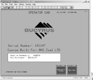
Operator’s Cab Title Screen
The information provided in the central area of the screen is machine specific and lists the machine serial number, the customer name and a listing of important documents and drawings associated with the machine.
The 2 buttons available, if touched, will cause the display to refresh with the information of the desired screen.

Operator’s Main Menu Screen The Main Menu screen will provide the operator with a choice of several buttons to select. Touching the screen in any of these button areas will cause the display to change to the requested option. Many of these screens will be displayed in the following pages. Several screens have an INFO button which will provide more detailed information concerning the functionality of listed buttons and switches.

Display Information Screen The Main Menu Information screen provides information about the various display screen options available through the Main Menu screen.

Active Alarms Screen
The Active Alarm screen will provide a list of all active alarms and faults that have been initiated on the machine.

Alarm History Screen

Walking Shoe Positions and Error Screen

Hoist/Drag Limit Calibration Screen
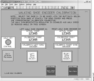
Walking Shoe Encoder Calibration Screen

Fault Counters and Operating Hours Screen

Tightline Parameters & Operating Data Screen

Operator’s Screen
The Operator’s Screen is the primary operational information tool to be visible to the machine operator during daily use of this machine. The controls available on this screen will provide the operator with the information needed to view “at a glance” the status of items required for digging and make changes in control settings.

Maintenance Menu Screen

Master Switch Calibration Screen
POWER CONTROL ROOM (PCR) DISPLAY SCREENS

Power Control Room Screen

Power Control Main Menu Screen

Set Panel Date/Time Screen

Communications and I/O Screen

Electrical Menu Screen
HOIST/DRAG LIMIT CALIBRATION
An encoder attached to the end of the hoist and drag drum shafts continually monitors the drum position during operation. As the bucket nears the preset limits, reference is gradually removed until the drum rotation is stopped. To prevent tight-lining or pulling the bucket into the boom, the sum of the hoist and drag ropes payed out in monitored. If this sum reaches a preset length, the hoist or drag functions will be stopped.
The limits must be recalibrated after changing the ropes or anytime maintenance is performed which alters the encoder versus drum rotation. Recalibration is required on the function, hoist or drag, being serviced.
HOIST LIMIT
To set the hoist limit:
1. Select the main screen via the Operator’s display.
2. Tie a flag on the hoist rope 33 feet from the socket at the dump blocks and hoist the bucket until the flag touches the boom point sheave.
3. Set the hoist and drag brakes, turn excitation OFF.
4. Place the hoist controller in the HOIST position and turn the rope zero switch on the right console to HOIST. Hold for 5 seconds. The Rope Limit Bypass LED will flash then go solid. The HOIST rope display on the OIT will display 32.78 feet.
5. To set the hoist lowering limit, lower the bucket until 2 turns of rope remain on the drum. Repeat steps 2 and 3 above.
6. Place the hoist controller in the lowering position and turn the rope zero switch to HOIST. Hold for 5 seconds. The HOIST rope display on the Operator’s display will blink and then indicate the length of rope payed out in feet.
After completing the above steps, the upper and lower hoist limits are set and the machine can be returned to service.
DRAG LIMIT
To set the drag-in limit:
1. Select the main screen via the Operator’s display.
2. Tie a flag on the drag rope 33 feet from the crows-foot socket and drag in the rope until the flag touches the lower fairlead sheave.
3. Set the hoist and drag brakes and turn excitation OFF.
4. Place the drag controller to drag in and turn the rope zero switch to DRAG. Hold for 5 seconds. The Rope Limit Bypass LED will flash then go solid. The DRAG rope display on the OIT will display 32.78 feet.
5. To set the drag-out limit, payout the drag rope until 2 turns of rope remain on the drum and repeat steps 2 and 3 above.
6. Place the drag controller in the drag-out position and turn the rope zero switch to DRAG. Hold for 5 seconds. The DRAG rope display on the Operator’s display will blink and then indicate the length of rope payed out in feet.
After completing the above steps, the drag in and out limits are set and the machine can be returned to service.
OPERATOR CONTROLS IN THE MACHINERY HOUSE
Power Control Room
The Power Control Room (PCR) encloses the electrical control components, preventing contamination from dirt, grease and dust. The segregation of control components into a room type module centralizes the responsibility of the electrician, thus improving maintenance.
The Power Control Room is supplied with a constant source of clean, filtered air which is under pressure to afford the ideal environment for the efficient operation of the electrical components.
The Starting Panel Controls used by the operator to start up and shut down the machine are located in the machinery house, near the center of the rear wall of the Power Control Room (PCR).
The following are the controls on the Starting Panel:
1-4. MG SET NO. 1 Controls and Indicators:
1. FIELD APPLIED - A green light that indicates the MG set motor fields have been applied.
2. VCB CLOSED - A green light that indicates the Vacuum Circuit Breaker for the MG set motor has closed.
3. START - A green pushbutton to start the MG set.
4. STOP - A red pushbutton to stop the MG set.
5-8. MG SET NO. 2 Controls and Indicators (same as for MG SET no. 1).
9. PHASE SEQUENCE - A green light that indicates that the phase sequence is okay.
10. START CYCLE - A green pushbutton that indicates its okay to start the M.G. sets.
11. BLOWERS - A pushbutton used to start or stop the motor blowers. A green light indicates the blower is operating.
12. AIR COMPRESSOR NO. 1 - A 2-position (OFF/ON) blue selector switch to turn the air compressor off or on for automatic operation.
13. OIL PUMPS - A pushbutton used to start or stop the oil circulating pump motors. A green light indicates the motors are running.
14. PROPEL OIL PUMPS - A green light that indicates that the propel oil pumps are operating.
15. SPACE HEATER - A 2-position (OFF/AUTO) green selector switch which turns the anticondensation heater off or on for automatic operation.
16. EXHAUST FANS - A pushbutton used to start or stop the MG set motor cooling fans. A green light indicates the fans are operating.
17-21. FILTER FANS NO. 1-5 - A pushbutton used to start the bleed duct fans and after a 5 second delay start each of the main filter fans. A green light indicates that the main fans are operating.
MACHINERY HOUSE REAR DOORS
The rear doors of the machinery house consists of a set of 3 doors on each half of the rear wall. Each set of doors includes 1 top door, and a left and right side door. The doors are opened and closed by hydraulic cylinders, actuated by manual hydraulic valves, one for each door, located at the center of the rear machinery house wall. Refer to the figure on the following page.
Either set of doors or both can be opened, however each set must be opened in sequence and closed in the opposite sequence.
CAUTION: DO NOT ATTEMPT TO OPERATE THE REAR DOORS UNTIL THE GREEN LIGHT IN ILLUMINATED, INDICATING THE DOOR LATCHES HAVE BEEN RELEASED.
CAUTION: DO NOT OPEN OR CLOSE THE REAR DOORS OUT OF THE SEQUENCE SHOWN. FAILURE TO FOLLOW THE SEQUENCE WILL RESULT IN DAMAGE TO THE DOORS.
CAUTION: DO NOT OPERATE THE MACHINE (DIG OR PROPEL) WITH THE REAR DOORS OPEN.
CAUTION: DO NOT LEAVE THE REAR DOORS OPEN DURING INCLEMENT WEATHER. FAILURE TO FOLLOW THIS CAUTION MAY RESULT IN DAMAGE TO THE DOORS OR TO THE EQUIPMENT INSIDE THE MACHINE.
MACHINERY HOUSE REAR DOORS
DOOR OPERATION
(Refer to the nameplate located near the control panel on the rear wall.)
To OPEN one of the doors:
1. Press the START button on the control panel to activate the hydraulic system.
2. Press the UNLOCK button for the particular door to be opened. The green indicator light be lit.
3. Open the top door using Valve #1 on the same side of the machine as the door to be opened.
4. Open the inboard side door using Valve #2.
5. Open the outboard side door using Valve #3.
6. Press the STOP button on the control panel to deactivate the hydraulic system.
To CLOSE one of the doors:
1. Press the START button on the control panel to activate the hydraulic system.
2. Close the outboard side door using Valve #3 on the same side of the machine as the door to be closed.
3. Close the inboard side door using Valve #2.
4. Close the top door using Valve #1.
5. Press the LOCK button for the particular door to be closed. The green indicator light should go out.
6. Press the STOP button on the control panel to deactivate the hydraulic system.
DOOR OPERATING SEQUENCE
CONTROL PANEL for the HOUSE REAR DOORS
Items on the control panel:
1. START - A yellow pushbutton which starts the rear door hydraulic system.
2. STOP - A red mushroom head pushbutton which stops the rear door hydraulic system.
3. LEFT SIDE UNLOCK - A black pushbutton which releases the upper and lower door latches.
4. LEFT SIDE UNLOCK - A green light which, when lit, indicates that the door latches are released.
5. LEFT SIDE LOCK - A black pushbutton which sets the upper and lower door latches.
6. RIGHT SIDE UNLOCK - A black pushbutton which releases the upper and lower door latches.
7. RIGHT SIDE UNLOCK - A green light which, when lit, indicates that the door latches are released.
8. RIGHT SIDE LOCK - A black pushbutton which sets the upper and lower door latches.
PRE-START INSPECTION
Visual inspection of the machine should be performed by operator and oiler at the beginning of each shift. A potential problem may be prevented if discovered early.
The following check lists can be used to help with the inspection.
General (all areas of the machine):
•Are guards, cover plates and safety devices secured in place? •Are all loose pieces stored in proper compartments or removed? •Check all hardware for tightness, missing bolts, nuts, pins, etc. •Is the proper lube supplied to all bearings and lube points? •Is all lube piping connected and filled? •Are all lube (grease) spills wiped up? •Is the machine thoroughly clean?
Tub ~ Check for the following items:
•Cracks, broken welds; •Deformed bottom plates; •Bent or damaged bulkhead plates; •Hook shoe(s) adjustment, with pin lock(s) in place; •No obstructions in roller path or main rotating gear; •Trail cable in correct position.
Machinery House ~ Check the following items:
•Automatic lube system with adequate lube supply; •All gearcases have proper oil level and all filters installed; •Air compressor crankcase oil level and drive belts’ tension; •Main house crane hoist not parked on a crossover beam.
Front End ~ Check the following items:
•Bucket - for wear, worn, broken or missing teeth, loose or missing pins, weld cracks; •Boom - for cracks, bent pipes; •The condition of the boom support ropes; •The intermediate boom support ropes with correct tension; •The condition of the hoist and drag ropes; •The condition of the fairlead components.
NOTE: If any problems are found after going through the above check lists, notify maintenance at once so that correction can be made.
TYPICAL START-UP
To start up the machine from a complete shutdown, use the following procedure. DO NOT start this machine unless you are completely familiar with the various controls. Perform the Pre-Start Inspection given on the previous page.
1. All the circuit breakers for the applicable controls and equipment must be closed and power on before proceeding with start-up. These are located primarily on the outside of the Power Control Room (PCR) and in the Operator’s Cab/Anteroom.
CAUTION: DO NOT use circuit breakers as ON/OFF switches. Make sure that all the circuit breakers are ON before starting the machine.
2. Go to the rear of the PCR and to the Starting and Metering Cabinet. Observe the various meters and the start-up controls and that the PHASE CHECK light is on.
IMPORTANT NOTE: During each component start-up always be ready to immediately stop it if there are any unusual sounds, smells, or visual effects. Always let the system being started come up to its normal operating speed before starting the next system. Any time a problem arises, check the OIT display in the Operators cab for assistance.
4. Start the motor blowers by pressing and releasing the START pushbutton. These blowers are used in cooling the DC motors. Check that the green indicator is lit and for the sound of the blowers.
5. Start the No. 1 M.G. Set by fully pressing and releasing the START pushbutton. Be sure that both green indicators are lit and that all meters are stabilized.
6. Start the No. 2 M.G. Set in a similar manner to the No. 1 M.G. Set.
IMPORTANT NOTE: If the vacuum breaker for the synchronous motor on the M-G set does not stay closed when the start button is released, repeated attempts to start the set should not be made. On a motor of this type, only attempt two successive starts if the motor is at ambient temperature. More than two attempts to start without success can damage the motor windings. Before attempting another start, the vacuum breaker starting circuitry or mechanism should be inspected by qualified personnel and its proper operation verified.
7. Start the Machinery House Filter Fans. Fully press and release the pushbutton. This will start the bleed duct fans. In approximately 5 seconds the main fans will automatically start and then the light will come on. These fans introduce clean air into the machinery house to cool the dragline operating equipment. They also maintain a positive pressure within the house to prevent dust entry if all the access doors are kept closed.
8. When the above systems have been started and are operating correctly, go to the Operators cab and observe the air pressure indicator in the OIT. This indicator provides a visual reference for the air system pressure and should indicate from 95 to 115 PSI during machine operation.
10. Sit into and adjust the operators seat.
11. Check the Hoist, Swing, Drag, and Propel Brake selector switches. If they are not at their
SET positions, put all of them there now, even if the red light in the switch is on.
12. Check to be sure that the hoist and drag controllers are in their NEUTRAL position and that there is no pressure applied to the swing pedals.
IMPORTANT NOTE: This machine is equipped with an electronic rope limit control system. This system is designed to aid the operation in avoiding serious mechanical damage to the machine due to hoist or drag bucket overtravel or bucket tight-lining. However, the system is not a substitute for careful operating procedures. The rope limit control system should be verified for proper operation on a daily basis. It is EXTREMELY important that the system be recalibrated after any rope or bucket rigging changes have been made. Refer to the Electrical Service Manual for this machine for proper procedures.
13. Press the EXCITATION START pushbutton on the operator’s console.
14. Turn the Hoist, Drag and Swing drag brake selector switches to the RELEASE position.
DANGER: THE MACHINE IS NOW OPERATIONAL. DO NOT LEAVE THE OPERATORS SEAT UNLESS THE CONTROLLERS ARE DEENERGIZED AND THE BRAKES ARE SET.
The operator controls the machine. PLEASE KEEP SAFE OPERATING PROCEDURES IN MIND AT ALL TIMES.
TYPICAL DIGGING CYCLE
Start a digging cycle with the bucket - on the ground, in the pit, and under the boom point. If the machine tends to rotate freely, apply just enough swing effort with the RIGHT controller in the opposite the direction of machine movement, to hold the machine steady.
OPERATOR’S CONTROLS
Begin dragging the bucket in by pulling back on the drag (left) controller. The more the controller is moved off its neutral position, the faster the bucket will be pulled toward the machine. As the bucket is dragged in, take care to remove any slack from the hoist rigging. Do not allow the spreader bar to rest on the bucket. Additional hoist pull can be applied to reduce the cutting depth and wear on the bucket heel. Do not drag the bucket any further than necessary to fill it. Dragging a full bucket wastes time and energy.
With the bucket full, a correct combination of hoist and drag controller movement will increase the hoist speed (right controller back) and decrease the drag speed (left controller forward) to lift the bucket out of the pit. Keep just enough tension on the drag ropes to prevent the bucket dumping. Too much rope tension tightens the “line of bucket carry” and positions the bucket close to the boom. This adds strain to the boom and slows down the hoist speed.
As soon as the bucket clears the digging face, slowly move the swing lever in the desired direction of machine rotation. A correct combination of hoist and drag effort with swing motion added avoids any excessive bucket and rope swing. Swing the machine and lift the bucket at the same time so that the bucket reaches the dump height and spoil location at the same time.
CAUTION: USE EXTREME CARE WHEN SWINGING TO INSURE THE BUCKET CLEARS ALL OBSTRUCTIONS AND THAT CLEARANCE EXISTS AROUND THE MACHINE.
Upon approaching the dump point, reverse the swing motion to bring the machine to a smooth and accurate stop. Co-ordinate the hoist and pay-out so that the bucket dumps as the machine stops swinging, and the bucket is empty as it starts back to the pit.
All the drives are “plugged” while digging to bring each motion to a stop and control the bucket as desired. There are no “operating” brakes on this machine. All the brakes on the drives are “parking” brakes only.
Release the drag rope tension by paying out some rope off the drum. This dumps the bucket. As the bucket dumps, move the right controller just slightly forward of its neutral position. Be cautious - do not allow an excessive amount of drag rope to pay out.
Never hold the load any longer than necessary to complete the dumping cycle. Once the material clears the bucket, slowly swing the machine back over the work area and lower the bucket into the pit, using a combined effort of the hoist and drag motions to place the bucket at its new dig site.
CAUTION: NEVER LOWER A FULL BUCKET OVER AN EXTENDED DISTANCE. DOING SO COULD CAUSE SEVERE DAMAGE TO THE ELECTRIC DRIVE COMPONENTS ON THIS DRAGLINE.
While operating the machine, observe its components for problems. Look for loose bucket pins; broken or frayed strands on the boom support, hoist, drag, and dump ropes; and bucket and rigging damage or wear. Keep an eye on the boom and the boom point. Report any maintenance requirements promptly to the appropriate personnel for attention so that unnecessary downtime can be minimized.
GROUND PREPARATION
Ground preparation is very important. The walking dragline requires a properly prepared ground base for operation. The tub and walking shoes must have full contact with the ground when the machine is digging or propelling. With the machine weight distributed over the entire tub bottom or the partial tub bottom and the two walking shoes area, moderate ground bearing pressure is obtained and the machine components are less stressed.
The ground supporting a walking dragline must be as near level as possible, firm, and dry. Sand, clay, and topsoil can be leveled easily with a dozer or grader. Sharp rocks and boulders cause point loading which will damage the tub and shoes structures and should be removed if possible. Where this is impractical, cover the working area with fill dirt to a sufficient depth that will eliminate the effects of the rocks.
This walking dragline can be propelled up or down a grade or ramp. Ramping the machine, moving it from one level to another, requires exercising great care because this situation subjects the tub and rotating frame to stresses much greater than experienced while digging. For a new machine, ramping should be restricted to no greater than a 5% grade (See Note). Later, this can be increased up to a 10% grade maximum. It is possible to traverse (cross) a 5% grade with this machine; however, AVOID CROSSING ANY GRADE IF POSSIBLE.
NOTE: When beginning to propel the machine, the transition from one grade to the next should gradual, no more than 2% over the length of the walking shoes (for this machine is approx. 70 feet). For example, starting from level ground, the machine should travel at least 3 shoe lengths before reaching a 5% grade.
The 8200 dragline design incorporates a calculated balance between boom length, boom angle, allowable bucket load, machine weight, and ballast used. During normal digging cycles, the center of gravity shifts from the front to the rear within a specific area called the “kern”. The machine maintains stability and relatively even ground bearing pressure over the entire tub area. If, for any reason, the digging radius or load increases to cause the center of gravity to extend out of the kern to the tub perimeter, an undesirable rocking motion will occur due to the cone shape that will develop in the ground under the tub. This results in an unstable machine and concentrated ground bearing pressure at the center of the tub. This condition is very detrimental to the machine and must be eliminated. Contact Bucyrus for consultation on this problem immediately.
WALKING/PROPEL OPERATION
WALKING MACHINERY
Two separate but identical propel machinery assemblies are located at each side of the rotating frame. These assemblies operate independently but are tied together electrically by encoders and a monitoring system to synchronize them during the step.
Each propel assembly consists of a DC drive motor, shafts and gearing, an eccentric, a walking arm with a stabilizing arm, and a walking shoe. The walking arm connects to the shoe through a ball joint that allows the shoe to swivel in all directions. It also permits limited lateral movement. Consequently, each shoe can adapt to ground contour within its design range.
A walking step is created when the eccentric rotates. During a walking step, the top of each eccentric turns toward the rear of the machine (away from the boom). The eccentric turns the walking arm in a path restricted by its stabilizer arm that generates the walking step through the shoes. Hook shoes, attached to the underside of the rotating frame, lift the rear of the tub during the step.
The walking process can be separated into 4 distinct phases, as follows:
• During the first quarter turn of the eccentric, the walking shoe moves from its “top dead center” or parked position toward the rear of the machine and down until it contacts the ground. Refer to PHASE 1 on the previous page. Just before the eccentric turns into the second quarter of its rotation, the rear of the machine and the rear edge of the tub raise and move slightly forward. This movement raises the tub out of any depression formed while digging and breaks any suction between the tub and the ground.
• During the second quarter turn of the eccentric, (PHASE 2) the shoes cause the machine to move rearward, dragging the front edge of the tub along the ground.
• The third quarter turn of the eccentric (PHASE 3) completes the propel movement of the machine. Near the end of this quarter turn, the machine is slowly lowered and the tub settles down onto the ground again.
• The fourth and final quarter turn of the eccentric raises the shoes into their park position (top dead center). The shoe return mechanism on each shoe realigns it parallel to the rotating frame as it is raised.
WALKING MACHINERY CONTROL
The Drag-Propel Contactors, located in a cabinet on the machinery deck in front of MG set #1 on the left side of the machine, electrically move the drag motors and the propel motors into and out of the drag generators loop, depending on what machine control mode the operator selects. In the DIG mode, the drag (left) controller in the cab controls the drag motors for digging. In the PROPEL mode, this same lever controls the propel motors for walking.
The walking shoes at each side of the machine are not mechanically connected. The position of the two shoes is electrically monitored to keep them in time/synchronized. This timing system detects when one shoe gets ahead of the other and generates an error signal to slow down the leading shoe and speed up the trailing shoe. This timing system functions to align the shoes only when they are approaching or have lifted off the ground and when the tub is nearing the ground after the step. This provides a smooth, shock-free propel movement. Once the shoes have contacted the ground and commenced the propel motion, the timing system will not alter their speed. The propel portion of the step will be completed. The encoders in this timing system are also used to detect when the shoes are at their “top dead center” or PARK position.
WALKING
Some preparations are required before moving the dragline. Its travel path must be adequately prepared. See the previous sub-section GROUND PREPARATION. The bucket must be positioned to suit the ground conditions. The machine must be rotated so its rear faces the desired direction of travel. Provision must be made for safely and correctly handling the trail cable during the move. DO NOT USE A WALKING SHOE TO PULL OR MOVE THE TRAIL CABLE to avoid damaging the trail cable.
The position at which the bucket is carried when the machine is propelled contributes considerably to the walking operation and is dependent upon the condition of the ground. When traversing firm,evel surfaces, the bucket should be suspended from the boom point approximately 1/3 the dump radius of the machine. The same position is used when propelling up a ramp. When propelling down a ramp, carry the bucket below the boom point. In all cases, the bucket should be high enough so that it will not touch the ground during a walking step.
“Heeling” the bucket while walking is done by letting the rear of the bucket contact the ground during the step and slide along when the tub slides rearward in the direction of travel. As the tub is lowered to the ground, the bucket is picked up as the boom point raises. THE BUCKET SHOULD NOT BE JERKED OFF THE GROUND. Heeling is useful while traversing dry, sandy, or powdery soil conditions to reduce the ground pressure under the sliding area of the tub and stop soil build up behind the tub’s front edge or to avoid shoe slippage on the ground.
Each operator will learn through experience where to carry the bucket while propelling to suit the ground conditions encountered. The above are general guidelines for any operator to follow initially for positioning the bucket for walking.
When all is ready for the machine to be moved, transfer the machine control from DIG to PROPEL mode. Refer to TYPICAL START-UP in this section for the procedure. Sound the signal horns to indicate the machine will propel.l
IMPORTANT NOTE:
The operator should check that the drag machinery is inoperative and that the transfer to PROPEL is complete. This is done by moving the left controller (drag) slightly forward off neutral and then back to neutral to see if the drag or the propel machinery moves. This check can avoid inadvertent damage to the boom or front end in case the drag motion is still activated when the controller is moved full forward to take a step.
Move the left controller forward and hold it there during the entire propel period. This controller is pulled back from neutral while in PROPEL ONLY to realign the two shoes if they get out of sync or to position them at top dead center for parking.
As the first walking step commences and the shoes move off their PARK position, the swing and hoist brakes will automatically set if they had not already been set manually. During extended travel over long distances, it sometimes becomes necessary to alter the direction of travel or reposition the bucket. This can be done without transferring to the DRAG mode. Stop the walking shoes in their PARK position. Check that the CLEAR TO SWING indicator is lit and the drag/propel brakes are set. Release the Hoist and/or Swing brakes then press the EXCITATION ON pushbutton. To continue propelling, set the hoist and swing brakes, release the drag/propel brakes and press the EXCITATION ON pushbutton.
During walking, if a ground roll develops at the front edge of the tub, “heel” the bucket for a couple of steps. If the tub roll persists, swing the machine 30o-40o to one side and propel one or two steps. This will spread the roll over the ground. Then return to the line of travel desired.
When the machine is walking, both shoes should contact the ground at the same time. If one of the shoes sets down on a high spot, or does not contact the ground, or steps into a soft ground area that will not support it, then the machine will rotate in relation to the tub if the walking step is completed. If this occurs and the operator can, he should stop the step before the machine is lifted and reverse the shoes up to top dead center position. He can then change machine travel direction with the swing motion and walk around the problem ground area.
SHUTDOWN
PARTIAL SHUTDOWN
A partial shutdown, for shift change or a lunch break, begins with a full machine rotation to reposition the roller circle and promote even wear.
Lower the bucket to the ground. Place both controllers in their NEUTRAL position. Place hoist, drag, propel, and swing brake selectors in the SET position (red indicator lights out). De-activate the controller circuits by pushing the STOP button on Operator Console (green light in START button will go out).
COMPLETE SHUTDOWN
A complete shutdown procedure starts with the steps listed under PARTIAL SHUTDOWN. Then the operator must go to the controls at the START-UP AND METERING cabinet located outside the power control room (PCR).
To completely shut down the machine perform the following to the controls on the START-UP panel:
• Press the M.G. set STOP buttons.
• Press the motor blowers STOP buttons.
• Press each filter fan pushbutton to STOP. • Turn each air compressor selector to OFF ~ only if the machine is to be stopped for an extended period of a week or more.
The machine is now shut down and ready for inspection, maintenance, etc.
CAUTION: INCOMING ELECTRICAL POWER EXISTS TO THE TRANSFORMERS, CABINETS, COLLECTOR RINGS, ETC. SO OBSERVE CORRECT CAUTIONS AND WARNINGS, AS INDICATED THROUGHOUT THE MACHINE AND SPECIFIC EQUIPMENT MAINTENANCE MANUALS. SAFETY FIRST IS BEST.
Section 3
Lubrication
Table of Contents
LUBRICATION PRINCIPLES.........................................................................................................5 LUBE POINTS ON D.C. MOTORS.........................................................................................7 LUBING ELECTRIC MOTOR BEARINGS WITH EMG LUBRICANT.......................................7 BEARING LUBRICATION DATA ..............................................................................................8 AUTOMATIC LUBRICATION SYSTEM ..........................................................................................9 Lube Point Chart .........................................................................................................................9 Lube Room (Plan View) ..............................................................................................................11 AUTO LUBE CONTROL PANEL (ELECTRIC)......................................................................12 Auto Luber COntrol Panel ~ Electric..........................................................................................12 OPERATION .........................................................................................................................13 IMPORTANT NOTES ON SYSTEM OPERATION...........................................................14 MANUAL LUBE REEL MPG OPERATION .............................................................................14 AUTOMATIC OPERATION ....................................................................................................15 FAULT DETECTION AND INDICATION .................................................................................15 PROGRAMMABLE CONTROL.............................................................................................15 RECOMMENDED CYCLE and ALARM SETTINGS ....................................................................16 LUBE CIRCUIT PRESSURE SWITCHES............................................................................17 SAFETY UNLOADER VALVES..............................................................................................17 LUBE CONTROL PANEL......................................................................................................18 4-WAY VALVE (Section View)....................................................................................................18 Schematic ~ AUTO LUBE PANEL GREASE.............................................................................19 Schematic ~ AUTO LUBE PANEL AIR ......................................................................................19 AIR OPERATED LUBE PUMPS............................................................................................20 Powermaster 4 Air Operated Lube Pump ...................................................................................21 AUTO LUBE RESERVOIR ~ Typcal..........................................................................................22 AUTO LUBE ~ MPG....................................................................................................................23 ROTATING FRAME ...............................................................................................................23 ROTATING FRAME CONTROL PANEL, Line-A .........................................................................23 Schematic - ROTATING FRAME (MPG).....................................................................................24 FRONT END CONTROL PANEL ~ LINES A AND B........................................................25 BOOM...................................................................................................................................25 FRONT END CONTROL PANEL ~ LINES A and B....................................................................25 Schematic - BOOM (MPG) .........................................................................................................26 Schematic - TRI-STRUCTURE (MPG) .......................................................................................27 Schematic - Fairlead (MPG).......................................................................................................28 ROLLER CIRCLE LUBE OPERATION...........................................................................28 Auto Lube - LUBE GUN (MPG)..................................................................................................29 AUTO LUBE ~ OGL....................................................................................................................30 OPEN GEARS......................................................................................................................30 Schematic - OPEN GEARS (OGL)............................................................................................30
LINCOLN TYPE SL-1 LUBRICANT INJECTORS..................................................................31 LUBRICANT INJECTOR OPERATION............................................................................32 INJECTOR ADVANTAGES ..............................................................................................33 LINCOLN SL-11 INJECTORS...............................................................................................34 Schematic - PROPEL BUSHINGS (OGL)..................................................................................35 LUBE DISTRIBUTOR............................................................................................................36 Valve with Indicator Stem and Adjustment .................................................................................36 OPERATING SEQUENCE OF MEASURING VALVES..........................................................37 DOUBLE OUTLET OPERATING SEQUENCE...............................................................37 SINGLE OUTLET OPERATING SEQUENCE.................................................................37 PROPEL BUSHINGS ............................................................................................................38 LUBE INJECTOR FLOW INDICATOR.......................................................................................38 PROPEL LUBE PIPING NOTES.....................................................................................38 ROPE SPRAY SYSTEM ~ WRL.................................................................................................39 CONTROL PANEL ~ ROPE SPRAY..........................................................................................39 Schematic - ROPE SPRAY (WRL)............................................................................................40 LUBE DISTRIBUTOR............................................................................................................41 MAINTENANCE PROCEDURE.......................................................................................42 Lube Distributor Torque Data.....................................................................................................43 GEARCASE LUBE CAPACITIES................................................................................................44 GEARCASE LUBRICATION - HOIST, DRAG, PROPEL..............................................................44 FLOW INDICATOR...............................................................................................................44 GEARCASE LUBRICATION - SWING.........................................................................................45 Swing Machinery Layout.............................................................................................................45 Gearcase Oil Level Sensor.........................................................................................................45 SWING OIL COOLERS.........................................................................................................46 Oil Cooler Assembly ..................................................................................................................46 SWING LOWER BEARING LUBE (MPG)..................................................................................47 GEARCASE LUBRICATION ~ PROPEL ....................................................................................48 GEARCASE LUBRICATION ~ HOIST and DRAG ......................................................................49 LUBE OIL PUMP ASSEMBLY ~ Typical ....................................................................................49 OIL CIRCULATING PUMP .....................................................................................................50 Oil Circulating Pump ..................................................................................................................50 THRUST BEARING REPLACEMENT .............................................................................50 CIRCULATING PUMP ASSEMBLY...................................................................................52 INSTALLATION OF CARBON GRAPHITE BUSHINGS....................................................53 PUMP SEAL REPLACEMENT.........................................................................................54 THRUST BEARING ADJUSTMENT.................................................................................57 LUBRICATION STANDARDS ......................................................................................................58 LUBRICATION BENCHMARKS...................................................................................................59 MPG - MULTI-PURPOSE GREASE......................................................................................59 Specific Requirements for MPG Lubricants ................................................................................60 RGL - REGULAR GEAR LUBRICANT...................................................................................62 General Requirements for RGL Lubricants .................................................................................62 DRAGLINE SPECIFIC DATA...........................................................................................64 Dragline Viscosity and Pour Point Requirements........................................................................64 SHOVEL & DRILL SPECIFIC DATA.................................................................................64 Shovel / Drill Viscosity and Pour Point Requirements .................................................................65
ASTM Standard Viscosity / Temperature Chart .........................................................................66 OGL - OPEN GEAR LUBRICANT.........................................................................................67 MINIMUM PERFORMANCE REQUIREMENTS ...............................................................68 ACSL - AIR COMPRESSOR (SCREW-TYPE) LUBRICANT................................................70 MPO - MULTIPURPOSE OIL.................................................................................................71 RWRL - RUNNING WIRE ROPE LUBRICANT.....................................................................72 STANDARD LUBRICATION INSTALLATION .........................................................................73 TYPICAL PIPE MOUNTING ......................................................................................................73 TYPICAL HOSE MOUNTING .....................................................................................................73 MINIMUM HOSE BEND RADIUS ...............................................................................................73 LUBE POINTS.............................................................................................................................75 PROPEL MACHINERY..........................................................................................................76 CENTER JOURNAL..............................................................................................................77 SWING MACHINERY.............................................................................................................78 ROLLER RAIL & ROLLER CIRCLE......................................................................................78 HOIST MACHINERY..............................................................................................................79 DRAG MACHINERY ..............................................................................................................80 FAIRLEAD .............................................................................................................................81 TRI-STRUCTURE.................................................................................................................82 BOOM...................................................................................................................................83 MISCELLANEOUS POINTS ..................................................................................................84
Section 3
Lubrication
LUBRICATION PRINCIPLES
The proper lubrication of this machine is vital to its successful, continued operation. Application of the CORRECT lubricant in the CORRECT amount at the CORRECT place as part of a PROVEN maintenance program is required to keep the machine operating at a level of productivity that will make your mining operation profitable. Proper lubrication will provide better component service life and reduce repairs and downtime. When not properly lubricated, moving parts wear quicker and fail sooner.
The major portion of this machine is lubricated PLC controlled automatic system that dispenses lube to selected points at pre-selected, timed intervals during machine operation. This system is covered in more detail further on in this section. It is important to the operation of this auto lube system that you become familiar with it and understand its operation so you can maintain and service it and keep it operable. It is also necessary that you periodically inspect on a regular basis the lubed points for lubricant application to insure the system is perf as intended.. Some components, due to their location and function, can not be readily covered by the auto lube system. A listing of these manually lubed areas that shows the lube application frequency is given in this section. You should become familiar with these points so you can service them properly at the intervals listed. A listing of the parts covered by the automatic lubrication system is also included. Per standard, the LUBRICATION FITTINGS used for manual service are the hydraulic type, pushon fittings, having 1/8 inch or 1/4 inch NPT threads. BUSHINGS and BEARINGS operating in a highly contaminated atmosphere (dust, grit, etc.) should be lubed until clean grease seeps out around the journal or seal, or comes out the purge fitting if one is provided. Overfilling an anti-friction bearing can cause it to run excessively warm. After lubing anti-friction bearings, especially those that are sealed such as in electric motors, remove the pressure fitting, or the relief plug when provided, and allow the bearing to purge itself of any excess lube during the first 10-15 minutes of operation. Replace the fitting or plug after that time. Grease in a bearing generally deteriorates gradually, not suddenly. Only a small amount needs to be added to it at regular intervals to maintain the proper lubricant level. Adding a small quantity of grease to the bearing every 600 operating hours, unless otherwise specified, is adequate. OPEN GEARS and PINIONS require a constant coat of a good grade of Open Gear Lubricant (OGL) acceptable for operation. Inspect all open gear sets at least once daily (every 24 hours) to insure they are coated with OGL. The automatic lubrication system is not designed to provide INITIAL COVERAGE. New parts installed or those cleaned during maintenance procedures must be fully lubed before commencing machine operation. Anti-friction bearings and bushings bust be hand packed or thoroughly coated with the correct lubricant. Open gearing and moving contact surfaces must be completely covered with their lubricant. Do not permit the lack of lubricant at start-up cause you to redo a repair job!
ENCLOSED GEARCASES must have their recommended lubricant level maintained. Check the lubricant level at the oil level plug or with the dipstick at least once weekly (every 150) hours). Inspect them daily (every 24 hours) for leaks. Change the oil in the gearcases at their recommended intervals, flushing each case with a light lube oil before adding the new gear oil. ALWAYS STORE THE USED OIL IN A SAFE CONTAINER UNTIL PROPERLY DISPOSED OF. DO NOT POLLUTE THE ENVIRONMENT!
Each of the planetary gearcases on this machine are equipped with a circulating pump and heat exchanger to cool the gear oil. It is recommended that scheduled oil samplings from the enclosed gearcases and air compressor crankcase(s) on this machine be taken and tested by an authorized and reputable lab to determine the contamination level of the sump oil. These samples should be obtained and tested every 30 operating days (600 hours). They should be taken when the oil is at its normal operating temperature and is well mixed in the case so they are good representative samples. This preventive maintenance procedure will permit you to determine the best time to change the oil, thus obtaining its best service life, and will simultaneously allow you to monitor the condition of the components. This program will pay you dividends in the long run. WIRE ROPE LUBRICATION (WRL) dislodges with the movement of one strand against another. Moisture can then enter the stranding and cause deterioration of the wire rope. The areas where the greatest deflection occurs are most susceptible to this contamination and early failure. On pendants, it is at or near the sockets. On other wire rope application, such as the hoist rope, it is at the sheaves or lagging. To increase the service life of any wire rope, apply the proper wire rope lubricant to the areas of its greatest deflection at periodic intervals. LUBRICANT SERVICE LIFE is adversely affected by unusually dusty or dirty environs and an atmosphere where high humidity or extreme temperatures exist. It shall, therefore, be the responsibility of the owner/operator of this machine to determine the most effective lubricant and lubrication interval for all the components according to the environmental conditions that prevail.
IMPORTANT NOTE: FOR AIR and HYDRAULIC QUALITY RECOMMENDATIONS and QUALITY MAINTENANCE PROCEDURES, refer to Section 9 – ENGINEERING DATA in this manual.
IMPORTANT NOTE: Filter all lubricants, especially oil, before adding them to the system or using them on the machine. Store lubricant drums on their side with the opening UP. Use only clean, uncontaminated lubricants!
CAUTION: Contact with or ingesting petroleum products can be harmful. Automatic lubrication systems operate under pressure. Before opening any lube supply line, relieve the system and that line in particular of any residual pressure.
LUBE POINTS ON D.C. MOTORS
LUBING ELECTRIC MOTOR BEARINGS WITH EMG LUBRICANT
Only qualified personnel should perform this maintenance operation. Proper lubrication of motor bearings requires following established procedures for all general conditions. First, we caution against over greasing! Establish a happy medium. Keep in mind that excess lube accumulates on armatures and windings, causing electrical problems and eventually failure. Initially lubricate all motor bearings on new equipment before placing them into service. After that, they require lubrication only every 6 months or yearly. NOTE: Many small motors use sealed bearings requiring NO lube for 2 or 3 years, or even longer. Add lubricant to motor bearings with unit stopped and drain plug removed, if there is one. Probing with a clean wire assures the old grease has not hardened and blocked the passage. After lubing, run motor with drain (vent) plug removed for a few minutes to allow any excess EMG to flow out. DO NOT FORGET TO REINSTALL THE DRAIN PLUG.
On some motors, the drain plug has been replaced with a lube vent fitting that automatically permits excess lube to flow out of the bearing cavity. See accompanying sketch. This vent fitting and line should be checked when lubing a bearing to make sure it is not plugged. If grease gun fittings are used, clean the fitting thoroughly before adding EMG lubricant. The addition of grease for each lubrication should be limited to about one-eighth of the maximum lube tabulated in Table X below. A shot of grease .25 inch (6 mm) in diameter and 1 inch (33 mm) long weighs about .03 ounce (1 gram). DO NOT OVER-GREASE MOTOR BEARINGS!
BEARING LUBRICATION DATA
Grease at each bearingMin.(Reservoir ½ full) & Max.(Reservoir 2/3 full)
For guidelines on purging motor bearing cavities and on replacing old bearing lube with new, refer to manufacturers publications and instructions.
AUTOMATIC LUBRICATION SYSTEM
The automatic lubrication system is a stand-alone computer subroutine running within the PLC which is designed to systematically ensure that major components which require constant lubrication are regularly lubricated at definable intervals, and also provides immediate indication in the event a lube fault occurs. The lube intervals, while initially set to specific values, can be modified to suit operating conditions using a graphical user interface. This interface is displayed on a CRT screen contained in a NEMA 12 gasketed enclosure located in the Lube Room. The Automatic Lubrication System operationally is divided into 4 separate systems. These are defined as follows:
1. Multi-Purpose Grease System (MPG) 2. Open Gear Lubrication System (OGL) 3. Propel System 4. Wire Rope Spray System (WRL)
PLC Controlled Automated Lubrication System Lube Point Chart
1. Multipurpose Grease System (MPG) - 68 points Rotating Frame Control Panel Line-A: Rotating Frame.................................................................... 20 Front End Control Panel Line-A: Boom.................................................................................... 15 Tri-Structure......................................................................... 12 Fairlead ................................................................................ 20 Line-B: Roller and Pins....................................................................... 1
2. Open Gear Lube Systems (OGL) - 34 points Open Gear Control Panel Line-A: Hoist and Drag Gears, final reduction only Rails and Rollers, Swing Pinion and Center Journal............ 18 Line-B: Propel Gears, final reduction only........................................ 16 3. Propel System (OGL) - 98 points Propel Control Panel Dual Line: Propel and Center Journal Bushings.................................... 98 4. Wire Rope Lube System (WRL) - 8 points Wire Rope Control Panel Hoist Ropes, Boom Point Sheaves........................................ 2 Hoist Ropes, Tri-Structure...................................................... 2 Drag Ropes, Fairlead Tower and Swivel................................ 4 Total:.................................................................................... 208 points
Each of the systems has a compressed air operated pump which forces the lubricant through each systems’ lines and electronically controlled valves, to direct the lubricant to the proper location within each of the subsystems. Each contains a lube reservoir, air-operated pumps, controls, and injectors or spray nozzles to meter the lube to points of application. The control panels and lube reservoirs, with pumps for each system, are located in the lube room at the front-left corner of the machinery house. The MPG, OGL and WRL systems are started at preset time intervals, while the Propel System is started only after a preset number of “walking steps” have been completed. In addition, the Wire Rope Spray system can be controlled by pushbuttons as the frequency at which the wire ropes require spray may increase depending upon usage. In this case the operator can apply additional rope spray to ensure maximum protection for the wire ropes during heavy usage. In addition, manual overrides are provided following an extended “downtime” period for crew shift changeover and during similar periods when additional lubricant is desireable. If a lube system fails to complete a timed lube operation, as indicated by a pressure switch, a fault exists and a warning is provided. Operationally this occurs if the a pressure switch contact fails to close within a preset time limit after a lubrication valve has been energized. If a fault should occur, the indicated system can be reset and operated by pressing either; • An associated manual pushbutton located in the Operator’s Cab • By using the CRT Interface screen in the Operator’s Cab. • By using the CRT Interface Screen on the Lube PLC Panel Door. The following chart provides; • Lubrication Interval Timer setting ranges and range of setting options • Lubrication Fault Timer settings and range of setting options • Lubrication Diagnostics lamps, audible alarms and system messages When a failure occurs and an alarm is activated, some of the more obvious causes to look for are: •Any mainline to an injector breaks. •The air supply fails. •The supply line is blocked. •Lube tank empties or pumps cavitates. •A pump fails. •The control system fails. When installing, servicing or repairing auto-lube equipment: KEEP IT CLEAN. Keep ALL lines free of dirt. Bleed out air and pre-fill lines with lube before placing into operation. To pre-fill, disconnect lines at the bearing only. Remove the cap on each injector face and expose the grease fitting. Fill the line from the injector to the bearing until lube flows from the hose. Connect the hose to the bearing and fill the bearing. (The auto-lube system is not designed to provide initial filling of bearings.
Remove the plugs on the main supply line, one at a time, starting at those nearest the pump. Pump lube into the system until ALL air bleeds out and lube flows from the opening. Replace the plug and proceed until ALL the lube supply lines are filled. NOTE: Do not use pipe unions on the boom or the gantry. Due to vibration and movement, hose and hose fittings work best in these areas. Allow slack where any structural movement is anticipated and avoid sharp bends. The operation of each of the circuits is controlled electronically to start and stop the air powered grease pumps. The injectors cycle during pump operation to meter the lubricant to the lube points. The system monitors operating faults which are indicated on the annunciator panel in the operators cab and the lube control panel. The Auto Lube system consists of: - OGL & MPG lube reservoirs fitted with air operated lube pumps (50:1 & 75:1 ratios). - Air supply from the compressed air system, with a manual shutoff valve for maintenance purposes and a pressure regulator for limiting operating air pressure to the lube pumps.
CAUTION: The air line shutoff valve must be open during machine operation.
- Solenoid-controlled air valves that direct air to the lube pumps. - Lincoln type SL-1 high pressure lubricant injectors. - Air and hydraulic pressure gauges located at strategic points for visually monitoring system operation. - High pressure switches in each circuit to signal control to shutdown pumps and terminate cycles at 2500 PSI (17.2 MPa).
- Safety unloaders (nonadjustable) in both pump delivery lines to protect the lube system from excessive pressure. - Pressure switch to activate the high air pressure warning. - Electric control panel to control the manual operation of the lube circuits and to help locate faults. - AC power supply network to control panel. - Programmable controller located in the Power Control Room to control the cycle and alarm times.
Lube Room (Plan View)
AUTO LUBE CONTROL PANEL (ELECTRIC)
The control panel is located in the lube room. The auto lube system includes a mechanical control panel with piping for each of the systems and one common electrical control panel.
Auto Luber COntrol Panel ~ Electric 1. ON - A red pushbutton turns panel power ON to the lube system. If not on, the fault lights on the panel and in the operators cab will be ON. 2. TRI-STRUCTURE - A pushbutton with a green light that when pressed activates the TriStructure rope spray lube system. 3. BOOM - A pushbutton with a green light that when pressed activates the Boom rope spray lube system. 4. FAIRLEAD - A pushbutton with a green light that when pressed activates the Fairlead rope spray lube system. 5. MACHINE OPERATING - A green light which indicates LE is energized. 6. FAULT RESET - A red pushbutton to reset a fault alarm.
7. MANUAL PROPEL - A yellow pushbutton that changes the 3 auto lube systems from DRAG to PROPEL. Press this button and any of the 3 manual buttons when testing the system’s propel operation. 8. PROPEL MODE - Amber light which indicates the machine is operating in PROPEL. 9. ROTATING FRAME-MANUAL - Pushbutton to manually cycle the Rotating Frame lube system. 10. ROTATING FRAME-FAULT - Red light indicates a fault in the Rotating Frame lube system. 11. OPEN GEAR-MANUAL - Pushbutton to manually cycle the Open Gear lube system. 12. OPEN GEAR-FAULT - Red light indicates a fault in the Open Gear lube system. 13. LINE A - An amber light that indicates that Line A is activated for the Rotating Frame system. 14. LINE B - An amber light that indicates that Line B is activated for the Lube Reel. 15. LINE A - An amber light that indicates that Line A is activated for the Hoist/Drag Open Gear system. 16. LINE B - An amber light that indicates that Line B is activated for the Propel Open Gear system. 17. PROPEL-MANUAL - Pushbutton to manually cycle the Propel lube system. 18. PROPEL-FAULT - Red light indicates a fault in the Propel lube system. 19. FRONT END-MANUAL - Pushbutton to manually cycle the Boom lube system. 20. FRONT END-FAULT - Red light indicates a fault in the Boom lube system. 21. LINE 1 - An amber light that indicates that Line 1 is activated for the Propel system. 22. LINE 2 - An amber light that indicates that Line 2 is activated for the Propel system. 23. LINE 1 - An amber light that indicates that Line 1 is activated for the Boom system. 24. LINE 2 - An amber light that indicates that Line 2 is activated for the Boom system.
OPERATION
A. If LE has been de-energized less than 60 minutes, the timers will restart when LE is energized and continue the lube intervals prior to the shutdown. B. If LE has been de-energized more than 60 minutes, the system will cycle immediately when LE is energized. Each of the 3 systems (OGL, Rotating Frame, Lower Frame) cycles in sequence and continue cycling per their programmed intervals. C. If LE is de-energized less than 15 minutes when in propel mode, the timer will restart and continue the lube intervals prior to the shutdown, or when LE is re-energized. D. If LE is de-energized more than 15 minutes in propel mode, the system will cycle immediately when LE is energized and continue cycling per the programmed intervals. A typical lube cycle operation for any of the circuits occurs in the following manner:
When a cycle is initiated by the PC, manually, or when LE is energized - the appropriate 3-way air solenoid valve is energized. Air to the pump causes the pump to pump lubricant to the distribution injectors and closes the vent valve. As the lubricant pressure builds in the circuit supply line, the injectors operate and push a metered amount of lubricant to the bearings, bushings, or open gearing. The lubricant pressure continues to build until it is sufficient to open the contacts in the pressure switch(es) in the circuit. When these contacts open, the controller de-energizes the air valve, shuts off the pump and vents the lube supply line to the reservoir. The lubricant pressure in the circuit decreases, allowing the injectors to recharge themselves for the next cycle. A cycle time is the interval between the initiation of lube cycles. The cycles will continue as long as LE is energized and NO fault is detected in the lube supply circuit.
IMPORTANT NOTES ON SYSTEM OPERATION
• The lube system Programmable Controller (PC) is programmed to operate either MPG or OGL circuits. Both circuit types will not operate simultaneously. • If any automatic lubrication supply circuit is operating at the time the machine’s drive system control is changed from DRAG to PROPEL, DRAG to BRAKES SET, etc., the circuit(s) operating will complete its (their) cycle before being deactivated. Any of the lubricant supply circuits can be cycled manually when power is ON the control panel, regardless of the machine control mode selection. The pushbuttons on the front of the control panel are used for manual operation. Manual operation of a lube supply circuit is useful for purging the lube lines, supplying additional lubricant to components or investigating a fault. It can also be used to verify or clear a fault. For manual operation, select the circuit desired by pressing one of the 6 pushbuttons provided on the auto lube control cabinet door. Push the Manual Cycle START button to start the lube cycle. More than one lube supply circuit can be operated at the same time. Once activated manually, a lube supply circuit will run until one of the following occurs: a. The contacts in the pressure switch(es) in the operating circuit CLOSE. b. The alarm time for that system is exceeded and a fault is indicated. c. The pushbutton for the circuit in operation and the ON / OFF button are pushed.
MANUAL LUBE REEL MPG OPERATION
The manual lube reel can be made operable anytime the auto lube system power is ON, regardless of the machine drive mode. Press the Manual pushbutton on the front of the Rotating Frame and hold for 2 seconds to activate the manual lube. The manual lube system does not have a switch which provides a continuous supply of lube to the lube gun when in use. The system will operate for 40 minutes or until the Manual STOP button is pushed. Using the STOP pushbutton de-energizes the air solenoid valve for the MPG pump, and reactivates all the other auto lube supply circuits. If the 40 minute time period is exceeded, the other MPG supply circuits will be automatically reactivated.
The manual lube reel will allow lubrication with MPG to any point within reach of its 25 ft. hose.
CAUTION: MPG lubricant in this hose can be under considerable pressure. To avoid harming personnel, never point it toward someone while opening the dispensing valve. Use extreme care when operating this unit.
AUTOMATIC OPERATION
An automatic lubrication cycle for any auto lube circuit is defined as the time from the start of one lubrication cycle to the start of the next.
FAULT DETECTION AND INDICATION
This automatic lubrication system is continuously monitored and indications are given for the following: · Machine operating mode. · Lubrication in process. · Lubrication system fault. · Air pressure fault. A Programmable Controller controls the auto lube system when power is ON. Fault indications are provided by lights located in the operator’s cab and on the lube control panel. Fault lights are accompanied by an audible alarm. Each of the auto lube supply circuits contains a preset alarm time (the crawlers lube has two). If the pressure switch contacts in the lube circuit being serviced do not open before the programmed alarm time, a fault is announced. The air solenoid valve for the lube pump circuit is de-energized. A fault will be announced on the annunciators in the operator’s cab and on the Auto lube Control Panel. Using the ALARM SILENCE button on the operator console in the cab to silence the alarm horn and cancel the fault. The faulted circuit may be started by using the manual pushbutton. For further information and instructions on the Programmable Controller, its functions and use, refer to the ELECTRICAL SERVICE MANUAL for this machine.
PROGRAMMABLE CONTROL
The auto lube system is controlled by a programmable controller located in the Power Control Room. An operators interface terminal (OIT) on the front of the controller provides access to the programmable controller for resetting the cycle and alarm times. For instructions, refer to the ELECTRICAL SERVICE MANUAL for this machine.
NOTES:
RECOMMENDED CYCLE and ALARM SETTINGS
1. The cycle time is based on bearing requirements. Changes to these values must be authorized by Bucyrus. 2. Additional time may be required due to the lubricant used or to ambient temperatures. 3. Line B of the Front End lube system supplies lube to the manual lube gun located in the rotating frame by the LH roller inspection hole. 4. Bearings are lubed after 2 steps.
LUBE CIRCUIT PRESSURE SWITCHES
High pressure switches are used to signal the controller (PC) that the lubricant pressure in a circuit has attained the level sufficient for pump shutdown and cycle termination. There are 7 of these switches used on the machine in the automatic lubrication system. They are located at various points around the machine that best insure lube distribution has been made throughout the 7 circuits. • FRONT END (MPG) - The pressure switch for Line A is located on the right side of the boom point. Line B has no pressure switch. • ROTATING FRAME (MPG) - The pressure switches for Line A and Line B are located in the supply lines under the machinery deck. • OPEN GEARS (OGL) - The pressure switch for Line A is located on the back of the left hoist gearcase. The pressure switch for Line B is located on the front of the left propel gear guard. • PROPEL BEARINGS - The pressure switches (2) for Lines 1 and 2 are located below deck at the rear of the right hand outboard bearing.
These switches are all double make, double break units that have snap action switching elements. They automatically reset by a snap action of the switch. DO NOT PLUG THE DRAIN PORT on the switch. Each switch is adjustable externally within the ranges listed on it. In this auto lube system, each switch is to be within the ranges listed on it. In this auto lube system, each switch is to be adjusted so its contacts open at 2500 PSI (17.2 MPa) and re-close at 1900 PSI 13.1 MPa). Check these settings with a gauge installed in the circuit as close as possible to the switch while manually cycling the lube circuit.
SAFETY UNLOADER VALVES
A safety unloader valve is provided in the OGL and MPG pump circuits to protect against excess lubricant pressure that could damage the system components. The unloader valve vents the lubricant directly to atmosphere when the circuit pressure exceeds 4000 PSI (27.6 Mpa).
LUBE CONTROL PANEL
4-WAY VALVE (Section View)
NOTE: The 4-way hydraulic valve operation will be fouled if the operator filter is left in place. Check and remove from new valves at installation.
4-Way Valve (2-Sol.) Functions:
Schematic ~ AUTO LUBE PANEL GREASE
1. When coil-1 (C1) is energized and coil-2 (C2) is de-energized, line-A will be supplied with grease. 2. When coil-2 (C2) is energized and coil-1 (C1) is de-energized, line-B will be supplied with grease.
Schematic ~ AUTO LUBE PANEL AIR
AIR OPERATED LUBE PUMPS
NOTE: The AIR PRESSURE REGULATOR and AIR SOLENOID VALVES used in this automatic lubrication system are covered in Section 5 - THE COMPRESSED AIR SYSTEM in this manual. Refer to this section for more detailed information.
The following air pumps are used in the lube system on this machine:
Ratio:
Control Panel Model Type Lube-to-Air Pressure
MPG:
Rotating Frame 1904 Powermaster 4 75 Front End 1904 Powermaster 4 75
OGL:
Open Gears 1904 Powermaster 4 75 Propel Bearings 1904 Powermaster 4 75 Wire Rope Lube 1910 Powermaster 4 22
WARNING:
• DO NOT exceed the 200 PSI working pressure of the airmotor or the lowest rated component in your system. • DO NOT alter or modify any part of this equipment • DO NOT operate this equipment with combustible gas. • DO NOT attempt to repair or disassemble the equipment while the system is pressurized. • TIGHTEN all fluid connections securely before using this equipment. • ALWAYS read and follow the fluid manufacturer’s recommendations regarding fluid compatibility, and the use of protective clothing and equipment. • CHECK all equipment regularly and repair or replace worn or damaged parts immediately. • IMPORTANT: Failure to heed these warnings including misuse, overpressurizing, modifying parts, using incompatible chemicals and fluids, or using worn or damaged parts, may result in equipment damage and/or serious personal injury, fire, explosion or property damage. The pump assemblies consist of a reciprocating pump powered by an air motor and are equipped with mufflers. These pumps are durable and will give adequate service life. When a pump will not stall with its lube discharge port blocked (plugged), then the pump should be rebuilt. Kits are available to rebuild the pumps. Refer to the Parts Book for parts information.
OPERATING PRECAUTIONS:
• The pump service life and efficiency will be reduced if the pump strokes per minute exceed 75.
• Add an air line restriction to limit the strokes if required. • Before servicing or cleaning the pump, disconnect the air lines and bleed off the system pressure. • To prime the pump, open the output line and slowly cycle the pump until all air is pushed out of the lines and lube fills the pump tube. Check that the pump will stall at operating pressure.
IMPORTANT:
Powermaster 4 Air Operated Lube Pump
• When assembling the air valve components, make sure that the power slide valve, the pilot slide valve and the valve actuator are in their “down” positions. The valve actuator should bridge the slide valves without interference. • If the acorn nuts are tightened with the valve parts misaligned, the valve actuator will be bent and the valve body will be ruined.
AUTO LUBE RESERVOIR ~ Typcal
AUTO LUBE ~ MPG
ROTATING FRAME
The Auto lube for the Rotating Frame supplies the center journal, the main rotating shaft bottom bearings, the intermediate hoist and drag shafts, the hoist and drag drum shafts, Tri-Structure and Fairlead. The air pressure regulator is set at 55 PSI (379 kPa). The end-of-line pressure switches are set at 2500 PSI (17238 kPa).
ROTATING FRAME CONTROL PANEL, Line-A
Schematic - ROTATING FRAME (MPG) ROTATING FRAME CONTROL PANEL, Line-A (20 points served)
FRONT END CONTROL PANEL ~ LINES A AND B
BOOM
The auto lube for the boom supplies the point sheaves, ball joint, cradle and boom support ropes with multipurpose grease (MPG). The system cycles once every 15 minutes. The alarm timer is set for 120 seconds. The air pressure regulator is set at 35 PSI (552 kPa). The end-of-line pressure switches at the boom point are set at 2500 PSI (17237 kPa).
FRONT END CONTROL PANEL ~ LINES A and B
Schematic - BOOM (MPG) FRONT END CONTROL PANEL, Line-A (15 points served)
Schematic - TRI-STRUCTURE (MPG) FRONT END CONTROL PANEL, Line-A (12 points served)
Schematic - Fairlead (MPG) FRONT END CONTROL PANEL ~ LINE A (20 points served)
ROLLER CIRCLE LUBE OPERATION
The Lube Gun, located on the right-front of the rotating frame structure and served by Line B from the Front End Control Panel, is used to manually lubricate the roller circle rollers. Refer to the graphic on the following page.
To grease the roller circle rollers: 1. Press the START button on the control box at the front of the machine next to the grease gun. 2. Grease the individual rollers with the grease gun. 3. If the system shuts off, press the START button again to resume greasing. 4. Press the STOP button when greasing is completed. NOTE: If the stop button is not pushed, the system will automatically shut off after 15 minutes. Grease the roller circle pins and foot pins every 30 to 60 days.
Auto Lube - LUBE GUN (MPG) FRONT END CONTROL PANEL, Line-B (1 point served)
AUTO LUBE ~ OGL
OPEN GEARS
The auto lube for the open gears supplies the roller circle rails, the hoist and drag gears and the swing pinions through Line A, which is active ONLY during the digging cycle. The main propel gear and pinion obtain supply from Line B, ONLY during the propel cycle. Line A is cycled on 10 minute intervals and Line B cycles on 3 minute intervals. The alarm for Lines A and B is set at 90 seconds. Air pressure is regulated at 55 PSI (379 kPa). The end-of-line pressure switches are set at 2500 PSI (17238 kPa).
Schematic - OPEN GEARS (OGL) OPEN GEARS CONTROL PANEL, Lines A & B (34 points served)
LINCOLN TYPE SL-1 LUBRICANT INJECTORS
These pressure-operating, spring-reset, series-installed injectors are supplied in banks mounted on manifolds or individually. Each injector expels a maximum of .08 cu. inch of lubricant from its outlet port each cycle. Dual outlet ports on each injector permit the injectors to be piped in series for increased lube supply to a common point. The quantity of lube to each point on this machine has been carefully designed by our engineers for proper coverage. Each injector output can be adjusted; however Bucyrus recommends that injectors initially be set and used at their maximum setting.
NOTE: MAXIMUM Operating Pressure:
3,500 PSI RECOMMENDED Operating Pressure: 2,500 PSI MINIMUM Operating Pressure: 1,850 PSI MAXIMUM Recharge Pressure: 600 PSI
CAUTION: STORED ENERGY! Contact with or ingestion of petroleum products can be harmful. Automatic lubrication systems operate under pressure. Before opening any lube supply line, relieve the system and that line in particular, of any residual pressure.
To set an injector for maximum output: 1. Loosen locknut. 2. Turn adjusting nut until there is a small gap at the top of the stem. 3. Orient the adjusting nut so that the opening is toward the front of the injector. 4. Tighten the locknut. To reduce an injector’s output: 1. Loosen locknut. 2. Turn adjusting nut clockwise (CW) until desired discharge rate is obtained. This forces the stem into the body, retarding the stem’s movement. 3. Set the locknut.
CAUTION:Do not turn adjusting nut down (clockwise) more than 5 full turns from the maximum discharge setting. Check output flow from injector at this time to ensure it is still operating. If not, back off adjusting nut until injector does consistently operate. Inspect the adjusted injector for operation over 3 or 4 cycles after returning machine to work to make sure it is functioning.
LUBRICANT INJECTOR OPERATION
STAGE 1: The injector piston is in its normal or reset position. The discharge chamber is filled with lubricant from the previous cycle. Under the pressure of incoming lubricant, the slide valve is about to open the passage leading to the piston.
STAGE 2: When the slide valve uncovers the passage, lubricant is admitted to the top of the piston, forcing the piston down. The piston forces lubricant from the discharge chamber through the outlet port to the bearing.
STAGE 3: As the piston completes its stroke, it pushes the slide valve past the passage, cutting off further admission of lubricant to the passage. The piston and slide valve remain in this position until lubricant pressure in the supply line is vented (relieved) at the pump.
STAGE 4: After the pressure is relieved, the compressed spring moves the slide valve to the closed position. This opens the port from the measuring chamber and permits the lubricant to be transferred from the top of the piston to the discharge chamber.
NOTE: The injectors may be mounted individually, or grouped in a manifold at one location.
INJECTOR ADVANTAGES
LINCOLN SL-11 INJECTORS
The SL-11 injectors on this machine dispense OGL to the swing pinions. These pressure operating, spring reset injectors are equipped with dual outlet ports which permit the injectors to be piped in series to increase the lube supplied if required. The SL-11 will expel a maximum of 0.5 cubic inches of lube each cycle. Although the injector output is adjustable, the system has been designed for the maximum output and adjustment is not recommended. NOTE: The operation of the SL-11 injector is the same as the SL-1 injector. Refer to page 3.7.2.
NOTE: MAXIMUM Operating Pressure: 3,500 PSI RECOMMENDED Operating Pressure: 2,500 PSI MINIMUM Operating Pressure: 1,850 PSI MAXIMUM Recharge Pressure: 300 PSI
Schematic - PROPEL BUSHINGS (OGL) PROPEL BUSHINGS CONTROL PANEL, Lines 1 & 2 (98 points served)
LUBE DISTRIBUTOR
** Gasket is included with item 4. Valve with Indicator Stem and Adjustment
OPERATING SEQUENCE OF MEASURING VALVES
DOUBLE OUTLET OPERATING SEQUENCE
A. Pressurized lubricant entering valve through line 1 forces pilot piston down, allowing pressure to be applied to top of main piston. Main piston begins to move down. B. Main piston moving down under pressure forces lubricant from its chamber, past the lower land of the pilot piston and out port “B” to the bearings. C. During the next operating period, pressure is applied to line 2 and the above operating sequence repeated with the pistons moving in the opposite direction. This time lube moves out port “A”. D. Indicator stem shows when valve is operating. Valve discharge can be varied by adjusting screw in packing gland to alter main piston
SINGLE OUTLET OPERATING SEQUENCE
A. When a dual line lubricating valve is cross-ported (converted to single discharge) the operational sequence of the valve itself does not change. As shown above, supply lines are pressurized alternately and piston movement remains the same. The only difference is that the total discharge (2 x disc./piston stroke) of each valve operation is directed out one outlet to a single bearing. NOTE: ONE DISCHARGE OUTLET MUST BE PLUGGED WHEN A SINGLE OUTLET IS DESIRED.
PROPEL BUSHINGS
The auto lube for the propel machinery supplies the propel gear bushings, propel shaft inboard and outboard bearings, the walking cams, stabilizer arms and walking shoe swivels. The alarm timer is set for 90 seconds. The system cycles every 3 walking steps during propel. The system will cycle on 5 minute intervals when in the propel mode and sitting idle. The air pressure is regulated at 55 PSI (379 kPa) and system pressure switch setting is 2500 PSI (17238 kPa).
LUBE INJECTOR FLOW INDICATOR
PROPEL LUBE PIPING NOTES
• Adjust all VSL-8 valves at the inboard and outboard bearings and at the center journal (5 places) to ½ their maximum capacity (adjust down 10 revolutions). • Adjust the VSL-4 valve at the center journal to its minimum capacity (adjust down its max. revolutions). • Adjust all VSL-8 valves at the ball joint pins to ½ their maximum capacity. Lube points 83, 84, 85 & 86 (Refer to the schematic). • BE EXTREMELY CAREFUL NOT TO ADJUST THE FLOW IN ANY VALVE DOWN SO FAR AS TO COMPLETELY SHUT IT OFF. The indicator stem must move or no lubricant will be delivered. DO NOT ADJUST DOWN TO LESS THAN 25% OF FULL FLOW.
ROPE SPRAY SYSTEM ~ WRL
The rope spray lube system supplies an oil spray to the hoist ropes at the boom point and at the deflecting sheaves in the tri-structure, and the drag ropes at the fairlead upper and lower drag sheaves. The system is operated manually by a set of 3 pushbuttons - either from the operator’s control console, or the Auto Lube Electric Control Panel in the Lube Room. To lube the ropes, press and hold only ONE of the 3 pushbuttons at a time, preferably as the ropes are moving, spooling off the drum.
OPERATION:
1. Open Valve [A]. 2. Open Valve [H] for Hoist Ropes at Boom
Point; then close. 3. Open Valve [B] for Hoist Ropes at Tri-
Structure; then close. 4. Open Valve [D] for Drag Ropes. 5. Close Air Valve [A]. 6. Close Valve [D].
NOTES:
• Only one Lube Valve, [B], [D], or [H] should be open at one time. • Air Pressure Regulator [R] should be set to 80 psi. • For best results, lube cables while they are moving.
CONTROL PANEL ~ ROPE SPRAY
While operating the lube system, observe the amount of lube deposited on the ropes. The spray from each nozzle is fan shaped and should be oriented in-line with each rope, not perpendicular to it. The boom and tri-structure lines spray near one sheave each, the fairlead sprays near 2 sheaves, for a total of 4 sheave location. A regulator is installed at each of the 4 locations in order to vary the amount of spray lube as required. Each pushbutton will simultaneously operate a solenoid valve on the Lube Control Panel for the lube supply and one near each regulator for the air supply.
NOTE: This system uses wire rope lube (WRL) from a reservoir in the lube room. DO NOT USE OGL or MPG! BEFORE operating the rope lube system, check the lube reservoir to be sure that WRL lubricant is being used, then open the air valve to the lube pump. Lube the boom, tri-structure or fairlead separately. To shut off the system, close the air valve to the pump. Lubricate the ropes every 8 hours, or less, depending on mine conditions. Set the air pressure regulator at 50 PSI (345 kPa).
CAUTION: Do not disconnect the air or lube pump lines when the lube or air gauges indicate pressure.
Schematic - ROPE SPRAY (WRL) WIRE ROPE LUBE CONTROL PANEL, 3 Lines (8 points served)
LUBE DISTRIBUTOR
Distributor (or Feeder) Section: Each individual distributor section contains a piston and grooves, ports and drilled passageways for the flow of lubricant, as shown in Figure #1. Distributor Assembly: A distributor assembly is a manifold consisting of three or more intermediate sections plus an inlet and end section, as shown in Figure #2. The assembly is held together with tie rods and nuts and there are gaskets between each section.
Figure #1 LUBE DISTRIBUTOR TERMINOLOGY
MAINTENANCE PROCEDURE
Blockage in the system is caused by one of the following: 1. A crushed line anywhere in the system. 2. A blocked bearing. 3. An improperly drilled fitting. 4. A blocked distributor (or feeder) assembly.
If blockage exists, proceed as follows: Use a hand grease gun, preferably with a gauge as shown. Apply the hand gun to the fitting, temporarily located in the inlet of the distributor, and stroke the pump. If the system will not cycle below 1500 psi, proceed as follows: Step #1: Remove, one at a time, each test plug which is common to a discharge port, and stroke the hand pump after each plug is removed. If pressure drops then blockage is downstream from the last outlet so tested. (When plugs are removed, trapped lubricant will usually surge out of the test plug hole which is common with the blocked out-going line.) If lubricant is not discharged through open test ports with all plugs removed, blockage is inside the distributor.
Step #2: If the blockage is in the distributor, it must be disassembled and cleaned. Remove the assembly from the machine.
Make a note and sketch as to the arrangement of the sections. For example: inlet, 10T-20S-10T, end. Before dismantling assembly, it is wise to remove end plugs only and, with strong finger pressure, work piston back and forth without removing same. (on oil system, if all pistons are movable, it is wise to replace and retighten the end plugs and re-test the assembly while on the bench. For the particle of dirt which caused the blockage may have been dislodged and the assembly may be back in A-1 working order with no further cleaning or disassembly.) Figure #1
If the piston is jammed, proceed with disassembly. Dismantle distributor by first removing tie-rods. With individual sections on the bench, remove the hex head plugs from both ends of each section. Now taking one section at a time, remove the piston. If it appears to be stuck, try removing it from the other direction. If it is badly jammed, it may be necessary to use a brass rod to tap it out. Now flush the section and piston in a clean suitable solvent until all the lubricant has been cleaned away. Blow out all ports thoroughly and use a small piece of wire to make sure that all passages are clean and open. Next inspect the cylinder bore carefully for scratches, score marks, or other damage. Inspect the piston in the same manner. If either of these parts is damaged, a new section should be installed. If the distributor section and piston both appear in good condition, reassembly as before making certain that the piston slides smoothly but snugly in the cylinder bore. Repeat the operation on each section. Take care, however, not to replace piston in any section except the one from which it was removed. (Early models of the new M and MX Distributors with Check Valves, employed a nylon ball in the circular check valve, located at top center of each Intermediate Section. Under heat or special pressure conditions, these nylon balls, now replaced by steel, would sometimes become deformed causing blockage. Replace if necessary.) After all sections have been cleaned, blown out, inspected and found to be in good condition, reassemble the distributor assembly by following your sketch. IMPORTANT - use the torque settings listed below. Test the operation of the assembly on the bench by pumping lubricant (preferably oil) into the inlet of the distributor with a hand grease gun. If it now functions properly, replace it in the system and again test for proper operation. REMEMBER Ä DIRT AND FOREIGN MATERIAL ARE THE WORST ENEMIES OF ANY LUBRICATING SYSTEM. All servicing should be carried out under the cleanest possible conditions.
Lube Distributor Torque Data (Ft.Lbs.)
MJ M-MV MX
Tie Rod Nuts 12 20 25
Alternate Outlets 10 10 24
Check Valves 10 15 19
End Plugs 15 15 45
NOTES:
1. Re-stack distributor according to your sketch. 2. Check proper assembly, including gaskets, etc. 3. Draw up assembly to proper torque settings. 4. Test distributor with light oil.
GEARCASE LUBRICATION - SWING
Swing Machinery Layout Machine rotation is provided by four swing motors and is initiated by movement of the right or left motion of the right-hand joystick on the operators console.
Gearcase Oil Level Sensor
The swing motors transfer rotation through a Planetary Gearcase to the rotating gear. Heating of the planetary gearcases is moderated using oil coolers which circulate warmed oil from the swing motors’ planetary gearcase to the cooler and back again after being cooled.
SWING OIL COOLERS
The oil coolers are mounted in pairs immediately in front of the swing motors.
VIEW A-A Oil Cooler Assembly (RH Shown - LH Opposite)
Each assembly is comprised of two cooling units, one for each of the swing motor planetary gearcases. The cooling unit is designed to reduce oil temperature from 175o deg. F to 160o F, and is designed to handle 20 GPM with ISO 320 type oil. NOTE: Lube capacities and specifications are located elsewhere in this section of the manual. Oil pressure to the coolers is provided by a flange mounted gear pump with a mechanical seal, which is powered by a close coupled 5 HP, 1200 RPM motor. Each of the coolers is provided with a low pressure in-line filter with a single element. The filter consists of a 40 micron wire mesh. The unit is monitored by a differential pressure switch and is provided with both electrical and visual indicators. The bypass and indicator are set at 25 psi. In addition, each unit is provided with a relief valve which is set to open at 120 psi. A visual pressure gauge is also provided on the output line of each of the coolers.
SWING LOWER BEARING LUBE (MPG)
GEARCASE LUBRICATION ~ PROPEL
GEARCASE LUBRICATION ~ HOIST and DRAG
LUBE OIL PUMP ASSEMBLY ~ Typical
OIL CIRCULATING PUMP
DANGER: Before opening the oil pump liquid chamber (pumping chamber, reservoir, jacket, etc.):
1. BE SURE THAT ANY PRESSURE IN CHAMBER HAS BEEN COMPLETELY VENTED THROUGH SUCTION OR DISCHARGE LINES OR OTHER APPROPRIATE OPENINGS OR CONNECTIONS.
2. BE SURE THAT THE DRIVING MEANS (MOTOR, TURBINE, ENGINE, ETC.) HAS BEEN “LOCKED OUT” OR MADE NON-OPERATIONAL SO THAT IT CANNOT BE STARTED WHILE WORK IS BEING DONE ON THE PUMP.
Failure to follow the above listed precautionary measures may result in serious injury or death.
Oil Circulating Pump
THRUST BEARING REPLACEMENT
1. Mark the head and casing before disassembly to insure proper reassembly. The idler pin, which is offset in the pump head, must be positioned toward, and equal distance between, the port connections to allow for proper flow of liquid through the pump. Remove the head from the pump. Do not allow the idler to fall from the idler pin. Tilt the top of the head back when removing to prevent this. Avoid damaging the head gasket. If the pump has a jacketed head plate, it will separate from the head when it is removed. The gasket between the head and jacket head plate must be totally removed. Use a new gasket when assembling the pump. 2. Remove the idler and bushing assembly.
3. Insert a length of hardwood or brass through the port opening between the rotor teeth to keep the shaft from turning. Bend up the tang of the lockwasher and remove the locknut and lockwasher from the shaft with a spanner wrench. 4. Carefully remove the rotor and shaft to avoid damaging the bracket bushing. 5. Remove the rotary member of the seal from the shaft and the stationary seal seat from the bracket.
6. Loosen the setscrews. With a spanner wrench, remove both end caps and lip seals. Remove the ball bearing and spacer collars. 7. Examine the seal chamber lip seal and remove it if it shows wear or damage. The lip seal must be removed if the bracket bushing needs to be replaced. 8. Clean all parts thoroughly and examine for wear or damage. Check the lip seals, ball bearing, bushing and idler pin and replace if necessary. It is often possible to reuse the idler pin rather than replace it. Note the position of the worn area on the pin. Press the pin out and reinstall - rotating the worn area at least 1/3 turn from the previous position. Check all other parts for nicks, burrs, excessive wear and replace if necessary. Wash the bearings in clean solvent. Blow out the bearings with compressed air. Do not allow bearings to spin; turn them slowly by hand. Spinning bearings will damage the race and balls. Make sure the bearings are clean, then lubricate with non-detergent SAE 30 weight oil and check for roughness. Roughness can be determined by turning the outer race by hand. If the bearings have roughness, replace bearings. Be sure the shaft is free from nicks, burrs and foreign particles that might damage the bracket bushing. Scratches on shaft in the seal area will provide leakage paths under the mechanical seal.
9. The casing can be checked for wear or damage while mounted on the bracket.
CIRCULATING PUMP ASSEMBLY
1. Install the bracket bushing. If the bracket bushing has a lubrication groove, install the bushing with the groove at the 6-o’clock position in the bracket. The bushing is carbon graphite, refer to “Installation of Carbon Graphite Bushings”. 2. Coat the shaft of the rotor shaft assembly with non-detergent SAE 30 weight oil. Start the end of the shaft into the bracket bushing, turning from right to left, slowly pushing the rotor into the casing. 3. Place the packing retainer washer in the bottom of the packing chamber and pack the pump with new packing. Use packing suitable for the liquid being pumped. Install the packing, staggering the joints from one side of shaft to the other. Lubricate the packing rings with oil, grease or graphite to aid assembly. A length of pipe will help to seat each packing ring. 4. Install the packing gland, capscrews and nuts. Back the rotor and shaft out of the casing just far enough to insert the packing gland through the side opening of the bracket over the end of the shaft. Make sure the gland is installed square and the nuts are tightened evenly. Tighten the nuts wrench tight then back off until the gland is slightly loose. 5. Coat the idler pin with non-detergent SAE 30 weight oil and place the idler and bushing on the idler pin in the head. 6. Using a .010-.015 inch head gasket, install the head and idler assembly on the pump. The pump head and casing were marked before disassembly to insure proper reassembly. If not, be sure the idler pin, which is offset in the pump head, is positioned toward, and equal distance between, port connections to allow for proper flow of liquid through the pump. If the pump is equipped with a jacketed head plate, install it at this time along with a new gasket. Tighten head capscrews evenly. 7. Slide the inner spacer collar over the shaft. 8. Press the lip seal, with the lip facing the end of the shaft, into the inner end cap and insert the end cap through the shaft end of the bracket. Turn the end cap clockwise (looking at shaft end) until it engages the threads. The end cap spanner wrench holes must be facing the rotor. Turn the end cap with a spanner wrench until it projects slightly from the opening on the side of the bracket. End cap must not be turned so far that the lip seal drops off the end of spacer collar on the shaft or the end cap becomes disengaged from the threads. If this happens, remove inner spacer collar, half round rings and end cap and start over at Step 7.
9. Pack the ball bearing with multipurpose grease, NLGI #2. Place on the shaft and push or gently drive into place in the bracket. 10. Press the lip seal, with the lip facing the end of the shaft, into the outer end cap and insert the end cap in the bracket. Turn the end cap in the bracket until it is tight against the bearing. 11. Put the lockwasher and locknut on the shaft. Insert a length of hardwood or brass through the port opening between the rotor teeth to keep the shaft from turning. Tighten the locknut and bend one tang of the lockwasher into the slot of the locknut. 12. Adjust the pump end clearance. Refer to “Thrust Bearing Adjustment”. 13. Lubricate all grease fittings with multi-purpose grease, NLGI #2.
DANGER: BEFORE STARTING THE PUMP, BE SURE ALL DRIVE EQUIPMENT GUARDS ARE IN PLACE. Failure to properly mount guards may result in SERIOUS INJURY or DEATH.
INSTALLATION OF CARBON GRAPHITE BUSHINGS
When installing carbon graphite bushings, extreme care must be taken to prevent breaking. Carbon graphite is a brittle material and is easily cracked. If cracked, the bushing will quickly disintegrate. Using a lubricant and adding a chamfer on the bushing and the mating part will help in installation. The additional precautions listed below must be followed for proper installation: • A press must be used for installation. • Be certain the bushing is started straight. • Do not stop the pressing operation until the bushing is in the proper position. Starting and stopping will result in a cracked bushing. • Check the bushing for cracks after installation. Carbon graphite bushings with extra interference fits are frequently furnished for high temperature operation. These bushings must be installed by a shrink fit: 1. Heat the bracket or idler to 750°F. 2. Install the cooled bushings with a press. 3. If facilities are not available to reach a temperature of 750°F., it is possible to install at 450°F.: however, the lower the temperature, the greater the possibility of cracking the bushing.
PUMP SEAL REPLACEMENT
1. Install the bracket bushing. If the bracket bushing has a lubrication groove, install the bushing with the groove at the 6-o’clock position in the bracket.
2. Install the lip seal in bracket. Prior to installing the rotating portion of the mechanical seal, prepare and organize the rotor shaft, head and idler assemblies and the appropriate gaskets for quick assembly. NOTE: Never touch the sealing faces with anything except clean hands or a clean cloth. Minute particles can scratch the seal faces and cause leakage. 3. Coat the idler pin with non-detergent SAE 30 weight oil and place the idler and bushing on the idler pin in the head. 4. Clean the rotor hub and bracket seal housing bore. Make sure both are free from dirt and grit. Coat the outer diameter of the seal seat and the inner diameter of the seal housing bore with non-detergent SAE 30 weight oil. 5. Install the seal seat in the seal housing bore. Make sure the drive pins are located in slots in the bracket bushing.
6. Place the tapered installation sleeve on the shaft. The sleeve is furnished with replacement mechanical seals. Coat the rotor shaft, the tapered installation sleeve and the inner diameter of the mechanical seal rotary member with a generous amount of non-detergent SAE 30 weight oil. Petrolatum may be used but grease is not recommended.
7. Place the seal spring on the shaft against the rotor hub.
8. Slide the rotary member, lapped contact surface facing away from the spring, over the installation sleeve on the shaft until it is against the spring. The slot in the seal must line up with the drive pin shaft. NOTE: For teflon seals the rotary member and installation sleeve go on together. Do not compress spring. Flush the sealing faces of both the rotary member and the stationary member with nondetergent SAE 30 weight oil just before installing the rotor and shaft. 9. Coat the rotor shaft with non-detergent SAE 30 weight oil. Start the end of shaft into the bracket bushing and turn from right to left, slowly pushing it in until the ends of the rotor teeth are just below the face of the casing. Leave the rotor in this position. Withdrawal of rotor and shaft may displace the seal rotating face and result in damage to the seal. 10. Using a .010-.015 inch head gasket, install the head and idler assembly on the pump. The pump head and casing were marked before disassembly to insure proper reassembly. If not, be sure the idler pin, which is offset in the pump head, is positioned toward, and equal distance between, the port connections to allow for proper flow of liquid through the pump. Tighten the head capscrews evenly. Remove the tapered installation sleeve from the shaft. 11. If the pump is equipped with a jacketed head plate, install it at this time along with a new gasket. 12. Slide the inner spacer collar over the shaft. 13. Press the lip seal, with the lip facing the end of shaft, in the inner end cap and insert the end cap through the shaft end of the bracket. Turn the end cap clockwise (looking at shaft end) until it engages the threads. The end cap spanner wrench holes must be facing the rotor. Turn the end cap with a spanner wrench until it projects slightly from the opening on the side of the bracket. The end cap must not be turned so far that the lip seal drops off the end of the spacer collar on the shaft or the end cap becomes disengaged from the threads. If this happens, remove the inner spacer collar, the half round rings and the end cap and start over at Step 12. 14. Pack the ball bearing with multi-purpose grease, NLGI #2. Place it on the shaft and push or gently drive into place in the bracket.
15. Press the lip seal, with the lip facing the end of the shaft, into the outer end cap and insert the end cap in the bracket. Turn the end cap in the bracket until it is tight against the bearing. 16. Put the lockwasher and locknut on the shaft. Insert a length of hardwood or brass through the port opening between the rotor teeth to keep the shaft from turning.
Tighten the locknut to 100 Ft.Lbs. This is equal to a 100 Lb. load applied 1 foot from the locknut. Bend one tang of the lockwasher into the slot of the locknut. If the tang does not line up with the slot, tighten the locknut until it does. Failure to tighten the locknut or engage the lockwasher tang could result in early bearing failure and cause damage to the rest of pump. Remove the length of hardwood or brass from port opening. Adjust the pump end clearance. Refer to “Thrust Bearing Adjustment”. Lubricate the grease fitting over the seal chamber with petroleum jelly, petrolatum (Vaseline) or other similar low melting point lubricant. Lubricate all other grease fittings with multipurpose grease, NLGI #2.
DANGER: BEFORE STARTING THE PUMP, BE SURE ALL DRIVE EQUIPMENT GUARDS ARE IN PLACE. Failure to properly mount guards may result in SERIOUS INJURY or DEATH.
THRUST BEARING ADJUSTMENT
1. Loosen the setscrews over the outer and inner end caps. Two for H and HL size pumps, 4 for all other sizes.
2. Turn the inner end cap clockwise, viewed from shaft end, until it projects slightly from the bracket, exposing approximately 3 threads. 3. Turn the outer end cap clockwise until the rotor is tight against the head and the rotor shaft cannot be turned.
4. Make a reference mark on the bracket end, opposite a notch on the outer end cap. Back off outer end cap 9 notches. 5. Tighten the inner end cap with a spanner wrench. Tap the spanner wrench lightly but DO NOT
OVER TIGHTEN as it will only damage the threads. 6. Tighten all setscrews that hold the inner and outer end caps to prevent their turning in the bracket.
7. The rotor and shaft should turn smoothly by hand 1 complete revolution. If the rotor and shaft don’t turn smoothly, go back and repeat Steps 1 through 7. Thrust Bearing Lubricants • Thrust Bearing: MPG • Seal Chamber: Petrolatum, Mobil Mobilarma 355 or equal NOTE: Lube both areas every 500 hours.
LUBRICATION STANDARDS
The selection of the proper lubricants for use on this machine is critical to its reliability. Improperly lubricated bearings, gears, couplings, and other precision parts quickly fail. FOR THIS REASON, LUBRICANTS SELECTED IN ACCORDANCE WITH THE “American Standards Testing Material” (ASTM) standards are recommended. These standards were compiled in cooperation with major petroleum suppliers to insure the consumer of an exact supply to specific requirements, regardless of source.
We recommend you advise your petroleum supplier of the following information to assist him in selecting the proper product for each application of this machine. Final acceptance of all lubricants supplied to this standard will be based upon their satisfactory performance in the intended application, and does not relieve the supplier of performance responsibility for brand name products. Operation of this machine in extreme temperatures (below -20oF/-29oC or above 110oF/44oC) requires special lubrication. Note the temperature ranges on the following lubricant specification sheets. Contact your local supplier, your Bucyrus representative, or the Service Department at Bucyrus for recommendations if you require additional information or advice.
• Store lubrication drums on their side, with the opening toward the top. • FILTER ALL OIL BEFORE ADDING IT TO THE SYSTEM.
• USE ONLY CLEAN and PROPER LUBRICANTS - KEEP IT CLEAN !
• DO NOT MIX TYPES or BRANDS of LUBRICANTS.
LUBRICATION BENCHMARKS
MPG - MULTI-PURPOSE GREASE
SCOPE: Performance requirements for Multi-Purpose Type Grease. APPLICATION: For heavy duty ball, roller and plain bearings. GENERAL REQUIREMENTS:
1. Heat Resistance - Shall be thermally stable, should not flow or harden in service.
2. Retention - Shall not exhibit high leakage.
3. Stability - Shall work continuously with a minimum change in consistency.
4. Water Resistance - Shall withstand water washout or leaching.
5. Reversibility - Shall be stable with repeated heating and cooling.
6. Pressure Separation - Shall resist oil-soap separation.
7. Dispensability - Shall have the ability to be pumped through automatic lubrication systems without the aid of heat tracing on the lube lines at the designated ambient temperatures.
8. Extreme Pressure - Shall withstand heavy shock loading.
9. Compatibility - Low temperature greases shall be compatible with mineral oil base greases and their oil seal material.
COMPOUNDING:
1. Suitable for producing the extreme pressure characteristics (without inert fillers) required for heavy duty ball, roller and plain bearing lubrication. 2. Suitable for producing a grease whose NLGI grades can be dispensed through an automatic lubrication system at the ambient temperature ranges as designated below, under “penetration”.
PROPERTY REFERENCE +30° to +110°F 0° to + 40°F +10° to -50°F
NGLI Consistency # ASTM D-217 2 1 Note #2 Typical Penetration ASTM D-217 265-295 310-340 Note #2 Dropping Point (°F-min.) ASTM D-2265 325 325 Note #2 Timken O.K.(load-lbs min.) ASTM D-2509 40 40 40 Shell Four Ball EP ASTM D-2596
Load wear index (kg –min.)ASTM D-2596 40 40 35 Load Weld (kg-min.) ASTM D-2596 200 200 200 Shell Four Ball Wear ASTM D-2266
Wear Scar (mm max.) ASTM D-2266 0.60 0.60 0.60 20KG for 1 hour @ 130oF @ 1800 RPM Copper Strip Corrosion ASTM D-130 Pass Pass Pass Rust Test ASTM D-1743 Pass Pass Pass
Viscosity of Base Oil ASTM D-88 Not less than 75 SUS @ 210oF (700 SUS @ 100oF). Motormatic Grease Worker ASTM D-217A 10% Maximum change in 10,000 strokes. Roll Stability Test ASTM D-1831 Not more that a 25% change in 4 hours. Wheel Bearing Test ASTM D1263 Not more than a 10% loss in 3 hours @ 200oF. Water Washout Test ASTM D-1264 Not more than 5% loss @ 100oF and not more than 15% loss @ 175oF. Pressure Oil Separation U.S. Steel test method - Cake penetration not less than 25% of grease penetration. Grease Mobility U.S. Steel and Socony Mobil Oil Company method - not less than 0.1 grams flow per second @ 0oF.
Specific Requirements for MPG Lubricants
NOTES:
1. Ambient Temperature - The ambient temperature shall be the temperature at the point of lubricant application.
2. Low Temperature Grease - For extended use in low temperature (+10° to -50°F) areas, this product should be capable of slumping in containers and should be pumpable through lube lines without the aid of heat tracing. In order to minimize compatibility problems, it is desirable that the thickener and additive system be the same as NLGI #1 and #2 greases.
3. Pumpability Tests - Major manufacturers of automatic lubrication systems check for pumpability at the designated ambient temperatures. The results of these tests should be sent to the Bucyrus International Service Department for review.
4. Seal and Packing - If a vendor should recommend a multipurpose grease which would require a special type of material for seals and packing, he should contact the Bucyrus International Service Department and discuss these requirements with them.
5. These performance requirements are benchmarks and not a specification. Therefore, meeting these limits as described above does not relieve the supplier of the responsibility associated with brand name products.
RGL - REGULAR GEAR LUBRICANT
SCOPE: Lubricant performance requirements for Regular Gear Lubricant. APPLICATION: For enclosed helical, worm, bevel, spiral bevel and other gears or gear assemblies subjected to severe shock loads. General Requirements for RGL Lubricants ASTM PROPERTY REFERENCE ACCEPTANCE
Oxidation Stability D-2893 Increase in Kinematic viscosity @ 210°F should not exceed 8%. Rust Protection D-665 No rust after 24 hour immersion in synthetic sea water. Corrosion Protection D-130 #1b strip after 3 hours @ 250°F. Foam Suppression D-892 Test Limits ~ Max. volume (ml) foam after: Sequence Temperature 5 min. blow 10 min. rest 1 75°F 75 10 2 200°F 75 10 3 75°F 75 10
Demulsibility D-2711-86 (per par. 3.2) AGMA* Grades: 2EP-6EP 7EP and up Max. % water in oil 1% 1% Max. Cuff 2.0 ml 4.0 ml Min. Free Water 60 ml 50 ml Timken O.K. Load D-2782 Typical Pass of # 55. EP Test – 4 Ball D-2783 1) Load wear index, min. kg = 40. 2) Load Weld, min kg = 250. Wear Test – 4 Ball D-2266 Wear Scar diameter, mm. max. = .6. 1 hr. @ 130°F @1800RPM @ 20kg. FZG Test Min. 11 stages passed. Separation Resistance Should not separate in storage and should maintain extreme pressure characteristics when subjected to centrifugal forces while in use. * American Gear Manufacturer’s Association
COMPOUNDING: • Should contain mild EP, agents of the leaded, sulfur-phosphorus or equivalent type. • Synthesized hydrocarbon fluids are not excluded as Regular Gear Lubricants.
Viscosity And Viscosity Index: For the maximum gear life the heaviest viscosity gear oil should be used, limited by the gearcase ambient temperature and duty cycle. The gear oil used must have a viscosity index equal to or greater than the required minimum of this specification. The AGMA (American Gear Manufacturer’s Association) grade is SUS (Saybolt Universal Seconds) as specified in this standard for gear oil viscosity. This tends to overcome the confusion of selecting a grade of oil based on SAE numbers (motor oil & gear oil, viscosity at what temperature, etc.). NOTES: 1. Ambient Temperature: The ambient temperature is defined as the air temperature in the immediate vicinity of the gearcase. Refer to the following in determining the ambient temperature: • Use atmospheric temperature for gearcases in an extreme exposed location. • Use machinery house temperature for gearcases inside of the house. Some machines are equipped with house heaters. • Use oil temperature for gearcases having either strip heaters or immersion heaters. • Gearcases exposed to the direct rays of the sun will run hotter and must therefore be given special attention. 2. Requirements For Selecting Gear Lubricant: • Lubrication of the gears and anti-friction bearings with the same gearcase oil. • Lubrication for the gears only whenever the bearings are sealed and lubricated separately. • Duty Cycle: - Semi-continuous operations such as: dragline hoist, drag and swing; shovel hoist, swing and crowd; drill rotary drive. - Intermittent operation such as propelling. 3. Guidelines For Selecting Temperature Range For Any Gear Oil: • Minimum Ambient Temperature: - Use oil pour point temperature when gears only are to be lubricated. - Use a temperature 10°F above pour point when gears and bearings are to be lubricated. • Maximum Ambient Temperature when oil viscosity is 2000 SUS • At many locations, a winter and summer grade of Regular Gear Oil will be used. • Use ASTM standard viscosity / temperature chart (later in this section) to plot temperature range.
DRAGLINE SPECIFIC DATA
1. Gearcases: The hoist, drag, swing and propel gearcases are located inside the machinery house.
2. Machinery house and gearcase heaters: • Machinery house heaters and/or gearcase strip heaters to be standard on the following: - Machines operating in climatic conditions which would cause the ambient temperature at the gearcases to drop to, and stay below, 30oF for a period of time. - Some machines will require just strip heaters on the gearcases while others will require house heaters as well.
• Machinery house heaters and gearcase strip heaters are optional equipement on all other machines.
Ambient Temperature
Dragline Viscosity and Pour Point Requirements 130oF to 30oF Below 30oF
Viscosity SUS @ 100oF ASTM D-445 - House & Strip Heaters
ASTM D-2161 Viscosity SUS @ 210oF ASTM D-445 220-240 House & Strip Heaters ASTM D-2161
AGMA Lubricant No. Viscosity Index, min. Pour Point oF, max. None Applicable House & Strip Heaters 85 House & Strip Heaters +30 House & Strip Heaters
SHOVEL & DRILL SPECIFIC DATA
Gearcases - Shovels: 1. The propel lower works gearcase is exposed. Some machines have gears and anti-friction bearings requiring splashed gear oil lubrication. 2. The hoist gearcase is located inside the machinery house. 3. Crowd and swing gearcases have gears and anti-friction bearings requiring splashed gear oil lubrication. On certain models these cases are located in exposed areas of the machinery house.
Gearcases - Drills: The rotary drive gearcase in the mast and the main machinery gearcase are exposed. Both gears and bearings are gear oil lubricated. Heaters: Machinery house heaters and strip heaters are optional equipment on all machines.
Shovel / Drill Viscosity and Pour Point Requirements
Ambient
45o to -50oF 75o to -20oF 105o to +10oF 130o to 30oF 150o to 10oF
Temperature Viscosity SUS ASTM D-445 284-347 626-765 1919-2346 - - - @ 100oF ASTM D-2161 Viscosity SUS ASTM D-445 55-61 70-76 122-138 220-240 470-530 @ 210oF ASTM D-2161 AGMA See note #1 2EP 4EP 7EP None Applicable SHC* Lubricant No. below Viscosity ASTM D-2270 130 95 90 85 155 Index, min. Pour Point ASTM D-97 -50 -20 +10 30 - oF, max.
*Synthesized Hydro-Carbon Gear Oil
NOTES:
1. AGMA standard gear oil specification does not include pour point temperature pour point as specified is an additional Bucyrus requirement. 2. If ambient starting temperature approaches lubricant pour point, external heaters may be required to facilitate starting and insure proper lubrication.
WARNING:If oil recommendation requires special seal or packing material, oil supplier should inform the Bucyrus Engineering Department of the need in time to obtain suitable seals or packings. WARNING: These performance requirements are bench marks and not a specification. Therefore, meeting these limits as described above does not relieve the supplier of the responsibility associated with brand name products.
ASTM Standard Viscosity / Temperature Chart
OGL - OPEN GEAR LUBRICANT
SCOPE: 1. This specification covers open gear lubricants produced with highly fortified blends of viscous fluids combined with additives to form stable, long lasting, high load carrying, wear resistant films that lubricate under mixed film and boundary conditions. 2. Materials furnished under this specification are primarily intended to lubricate open gears, but may also be used to lubricate racks, bushings, rails, rollers, dipper handles and propel mechanism components. 3. Materials furnished under this specification are intended to be dispensed intermittently by single line parallel, single line series progressive, and/or dual line progressive centralized lubrication systems. 4. This specification covers open gear lubricants that may be applied in service at temperatures ranging from -50oC/-58oF to 50oC/122oF. The particular grade or consistency selected must perform within the specific temperature range in which it is utilized. 5. Materials furnished under this specification may be asphaltic (bitumen) compounds, or blends of a thickener and mineral oils and/or synthetic fluids. They may be in the form of viscous fluids, semi-fluid greases or pastes. Specific product selection is the responsibility of the equipment operator/owner and is dependent on climate, application, performance and regional/ local regulatory requirements.
PHYSICAL CHARACTERISTICS: 1. These open gear lubricants must have excellent adhesive and cohesive qualities, must not chip or throw off, and must provide sufficient film thickness and scuffing resistance to prevent metal to metal contact between applications under all operating conditions. 2. Various grades or consistencies of open gear lubricants may be required to provide proper lubrication and application properties over a wide range of ambient temperatures. The consistency of the lubricant as applied must be appropriate for the method of application, and the in-service consistency shall be appropriate for the lubricant to meet or exceed the minimal performance requirements listed in the “MINIMUM PERFORMANCE REQUIREMENTS” section.
3. Viscosity, a fluid’s resistance to flow, is the principal physical characteristic of a fluid in terms of its ability to produce a lubricating film between two interfacing surfaces. All lubricating fluids possess a natural viscosity that may be altered (enhanced) by additives such as resins or polymers. Some “viscosity enhancers” are shear sensitive, which could result in insufficient protection of the lubricated components under high load, elevated temperatures and/or high shear conditions. The viscosity of the fluids utilized in the open gear lubricants shall be sufficient under operating conditions for the product to meet or exceed the performance requirements listed in the “MINIMUM PERFORMANCE REQUIREMENTS” section.
4. These open gear lubricants must be specifically formulated to protect surfaces, reduce wear, and provide satisfactory service life under all anticipated operating conditions. 5. These open gear lubricants must have excellent water tolerance and rust preventive qualities, as well as minimal dripping qualities for operation over wide temperature ranges.
MINIMUM PERFORMANCE REQUIREMENTS
PROPERTY REQUIREMENT Flash point of product as applied, ASTM D92 / ISO 2592 79 / 175 minimum oC / oF Flash point of base fluid(s) ASTM D92 / ISO 2592 232 / 450 minimum oC / oF Rust protection ASTM D 1743 Pass Copper strip corrosion ASTM D 4048 1b maximum rating 24hr. @ 100oC / 212oF Water spray off ASTM D 4049 15 37.8oC / 100oF 40psi / 2.8 kgf cm2, % mass loss Four ball EP test ASTM D 2596 weld point, minimum kgf 400 load wear index (LWI), minimum 90 Four ball wear test ASTM D 2266 or ISO 0.7 60 minutes @ 40 kgf, maximum scar, mm Anti-scuff, FZG procedure DIN 51354 12 A/2.76/50 method, minimum failure stage Deleterious particles ASTM D 1404 20 maximum number of scratches Adhesive properties Must adhere to surfaces at the lowest anticipated temperature
Lubricant retention, U.S. Steel Retention test Products with a base fluid viscosity of 160.8 mm2/s @ 98.9oC, 43 lbs./19.5 kg, 30 minutes Pass
Products with a base fluid viscosity of 160.8 mm2/s @ 98.9oC, 30 lbs./13.6 kg, 30 minutes Pass Pumpability*, Lincoln Ventablility test, nominal 400 / 28 maximum psi/kgf, cm2 @ lowest anticipated ambient temperature. *NOTE: Consult the lubricant system component manufacturer regarding any deviations from this requirement. Minimum Base Oil Viscosity
SPECIAL CONSIDERATIONS:
1. The material furnished under this specification must be dispensable through the distribution lines of a centralized lubrication system to the most remote application point, at the lowest anticipated operating temperature. It must not plate or plug components of the centralized lubrication system such as injectors, metering blocks or spray nozzles.
2. When the material furnished under this specification is formulated with solid film additives, particle size must not exceed 100 microns.
3. Should the material furnished under this specification contain a diluent to improve dispensability, special care must be exercised to ensure its compatibility with all centralized lubrication system components, i.e., gaskets, o-rings, vent valves, etc.
4. Diluent containing lubricants furnished under this specification must conform to the performance requirements in the “MINIMUM PERFORMANCE REQUIREMENTS” section, after the diluent has evaporated. PRODUCT ACCEPTANCE:
1. Open gear lubricants that meet or exceed the performance requirements in the “MINIMUM PERFORMANCE REQUIREMENTS” section should provide adequate lubrication characteristics for satisfactory component life. However, Bucyrus International, Inc. recognizes that laboratory tests simulate, but do not duplicate all actual mining excavation equipment component operating conditions.
2. A lubricant is one part of the lubrication process. Unacceptable, satisfactory or exceptional machine component life is dependent on the application of the correct uncontaminated lubricant, in the correct amount, at the correct time. Proper machine and lubrication system maintenance practices can have a greater influence on componenet life than specific lubricant performance characteristics.
3. Compliance with or exceeding the minimum laboratory performance requirements listed in the “MINIMUM PERFORMANCE REQUIREMENTS” section therefore, does not constitute an approval, endorsement or any other form of product acceptance by Bucyrus International, Inc.
4. Experience has shown that products that may be deficient in one or more of the characteristics provided in the “MINIMUM PERFORMANCE REQUIREMENTS” section can also provide excellent overall performance when applied correctly in well-maintained machine components.
5. Owners/Operators of Bucyrus mining equipment are encouraged to use open gear lubricants with proven acceptable service histories in similar equipment under similar operating conditions, and that are produced and supported by a reputable supplier.
ACSL - AIR COMPRESSOR (SCREW-TYPE) LUBRICANT
SCOPE: Lubrication performance requirements and recommendations for Air Compressor (Screw-type) Lubricants.
IMPORTANT NOTE
These lubricant performance requirements for screw-type air compressors are only good for A-C Compressor Corporation screw compressors. If the machine is equipped with air compressors manufactured by other than A-C you must refer to the vendor’s maintenance information provided with the machine and Section 7 of this manual.
LUBRICANT RECOMMENDATIONS:
The following lubricants are recommended: 1. If the ambient temperature is expected to always be above -26°C (-15°F), use either: Automatic Transmission Fluid (ATF) - General Motors Dexron III or Ford Type F. or Synthesized Hydrocarbon Fluid - Mobil Rarus SHC 924. 2. If the ambient temperature is expected to drop to -40°C (-40°F), use Mobil Rarus SHC 1024 or Phillips Philesco ISO32 or equivalent. NOTE: If the ambient temperature drops below -26°C (-15°F), it may cause the lubricant to thicken in the oil cooler and could result in unit shutdown after a short run. If this happens often and the compressor is being lubricated with ATF, it is recommended that a synthesized hydrocarbon lubricant be used, instead. NOTE: These performance requirements are bench marks and not a specification. Therefore, meeting these limits as described above does not relieve the supplier of the responsibility associated with brand name products.
MPO - MULTIPURPOSE OIL
SCOPE: Lubricant performance requirements for Multi-Purpose Oil. APPLICATION: The addition of a lubricant to the compressed air system (not for screw-type air compressor systems - see ACSL), hand oil cans, etc. GENERAL REQUIREMENTS:
1. Must be fluid at temperature applied. 2. Should contain rust inhibitor.
3. Motor oil - API service classification “MS”.
VISCOSITY RECOMMENDATIONS:
1. Air Line Lubricant
AMBIENT TEMPERATURE SAE NUMBER Below 10°F 5W Above 10°F 10W 2. Hand Oil Can - Viscosity suitable for application and temperature. NOTE: These performance requirements are bench marks and not a specification. Therefore, meeting these limits as described above does not relieve the supplier of the responsibility associated with brand name products.
RWRL - RUNNING WIRE ROPE LUBRICANT
SCOPE: Lubrication performance requirements for hoist rope lubricant. APPLICATION: Primarily for hoist ropes or any other running ropes where fatigue and not wear is of prime concern. GENERAL REQUIREMENTS: 1. Penetrate between adjacent wires in order to lubricate and protect them against wear and to keep the rope core from drying out and deteriorating. 2. Provide a lubricant between sheaves and wire rope. 3. Resist being washed off. 4. Protect against rusting or corrosion. 5. Form a non-sticky film so that dust and dirt will not build up on the wires. 6. Remain pliable and resist stripping at the lowest temperatures to which the rope will be exposed. 7. Preferably, it should form a light colored transparent film so that wear, corrosion or broken wires can be readily detected by inspection. 8. Be capable of easy application, both manually and by devices without being heated. COMPOUNDING:
Suitable for penetrating between the adjacent wires of a rope in order to lubricate them and also to replenish the lubricant in the core. SPECIAL REQUIREMENTS: 1. Must pass United States Steel Retention Test Using a Timken Tester 2. Shell Four Ball E.P. - (ASTM D-2596) Load wear index, kg., min.: 40 Load weld kg., min.: 250 3. Shell Four Ball Wear - (ASTM D-2266) Wear scar diameter, mm., max.: 0.60 4. Timken O.K. Load lbs., min. - (ASTM D-2782): 45 5. Copper Strip Corrosion - (ASTM D-130): pass 6. Suggested Application Temperature Ranges There should be a lubricant for each of the following temperature ranges: 110°F to 30°F 40°F to 9°F 10°F to -50°F
NOTE: These performance requirements are bench marks and not a specification. Therefore, meeting these limits as described above does not relieve the supplier of the responsibility associated with brand name products.
STANDARD LUBRICATION INSTALLATION
TYPICAL PIPE MOUNTING
For more than one hose, clip one and secre the others to the 1st with tiewraps. TYPICAL HOSE MOUNTING
MINIMUM HOSE BEND RADIUS
ASSEMBLY of REUSABLE HOSE FITTINGS
Step 1: - Cut the end of the hose square with a fine tooth saw or cut-off wheel. - DO NOT cut back outer cover of hose.
- Secure the socket. Screw the hose counterclockwise onto the socket until the hose bottoms. Back off 1/4 turn.
Step 2: - Liberally grease the nipple threads and the inside of the hose. Step 3: - Screw the nipple clockwise into the socket and the hose. Tighten until snug against the socket.
LUBE POINTS
CAUTION: LUBRICATION INSPECTION OR CLEANUP IS A DIRTY AND
DANGEROUS TASK IF NOT DONE REGULARLY. Follow these recommendations for machine lubrication and setup.
SAFETY CHECK LIST - for inspection, lubrication and maintenance
• Clean up spilled petroleum products immediately. •Do not use gasoline, naptha, turpentine, or similar solvents to remove oil or grease from your skin.
• Do not wear oil soaked garments. • Promptly remove any petroleum product that gets on your skin. • Do not use dirty wipe cloths. • Avoid breathing oil mist or solvent vapors. • Check all lubrication and air line connections, remembering that they could be pressurized. • Remove all lubricant accumulation from around bearings and gears. • Keep all walkways, ladders, stairs and floor areas clear of lubricants.
PROPEL MACHINERY
CENTER JOURNAL
HOIST MACHINERY
DRAG MACHINERY
FAIRLEAD
TRI-STRUCTURE
BOOM
MISCELLANEOUS POINTS
Section 4 Preventive Maintenance
Table of Contents
INTRODUCTION...........................................................................................................................3 ELEMENTS OF AN EFFECTIVE MAINTENANCE PROGRAM ...............................................5 SCHEDULED PREVENTIVE MAINTENANCE PROGRAM .....................................................5 GENERAL SAFETY CONSIDERATIONS................................................................................6 MAINTENANCE DURING MACHINE OPERATION........................................................................6 MAINTENANCE PRECAUTIONS ..................................................................................................7 PREVENTIVE MAINTENANCE FOR LUBRICATION.....................................................................8 LUBRICANT CLEANLINESS ...................................................................................................9 FREQUENCY OF INSPECTION AND MAINTENANCE...............................................................10 MAINTENANCE SCHEDULES ....................................................................................................10 DAILY CHECK POINTS...............................................................................................................11 WEEKLY CHECK POINTS.........................................................................................................15 MONTHLY CHECK POINTS.......................................................................................................20 QUARTERLY CHECK POINTS..................................................................................................21 SEMI-ANNUAL CHECK POINTS .................................................................................................22 ANNUAL CHECK POINTS...........................................................................................................24 MAJOR COMPONENT LOCATIONS..............................................................................29 MACHINE NOMENCLATURE .....................................................................................................29 BASE FRAME (Tub)..................................................................................................................30 WALKING SHOE .......................................................................................................................31 ROTATING GEAR & RAILS (Section View) ................................................................................32 ROLLER CIRCLE (Section View) ...............................................................................................32 PROPEL MACHINERY ..............................................................................................................33 DECK PLAN ..............................................................................................................................34 HOIST and DRAG MACHINERY ................................................................................................35 SWING MACHINERY................................................................................................................36 MACHINERY HOUSE................................................................................................................37 OPERATOR’S CAB and ANTEROOM ........................................................................................38 FAIRLEAD ASSEMBLY.............................................................................................................39 TRI-STRUCTURE ......................................................................................................................40 SAFETY, ROPES, TRI-STRUCTURE ........................................................................................41 BOOM ASSEMBLY....................................................................................................................42 BOOM SUPPORT ROPES ........................................................................................................42
Section 4 Preventive Maintenance
This section of the manual describes those aspects of preventive maintenance on the machine such as inspection, adjustment and routine repetitive tasks. Information related to lubrication techniques, frequency and service points is also partially included. Further detailed information can be found in Sections 3 and 5 of this manual.
At the end of this section are reproducible maintenance schedules that may assist in record keeping and maintenance scheduling.
INTRODUCTION
A Preventive Maintenance Programs is a systematic series of operations performed periodically on equipment to prevent breakdowns.
Any breakdown WILL reduce productivity and increase overhead expense. Machinery is only new at one point in time. From that moment, the machinery begins to deteriorate through use and aging. A well organized maintenance program will avoid unexpected high-cost breakdowns and will increase component life.
A systematic approach to the program should be followed and detailed records of all findings kept, to detect potential problem areas. Valuable time and effort can be saved if defects are corrected before they lead to a major breakdown. The records should be reviewed often and kept on file for future reference.
Personnel involved in the program should go through an established training program, to know WHAT to check and HOW to rectify any potential problem area. When personnel are able to do routine maintenance and normal repairs efficiently, downtime is reduced and machine productivity increased. Also, to keep the machine in good running condition, the necessary parts, tools and current information should be kept on hand.
Equipment maintenance is a science and its practice an art. This art can be divided into 6 types of operations - they are:
Inspection is probably the most important operation. Careful observation is required of all parts of the equipment. Slight abnormalities may not interfere with the equipment performance BUT those that are a deviation from the normal should be discovered early. When inspecting, notice placement, state of cleanliness, color, etc. of part(s).
Example: discoloration indicates overheating; all guards, bolts in place and good housekeeping. Cleaning and keeping clean is essential for good operation. Periodic cleaning should be more frequent on exposed parts than those which are contained within cabinets.
Parts, connections and joints should be free of dust, corrosion and other foreign matter.
A Feeling operation is used more often to check guarded rotating machinery for vibration due to worn parts, lack of lubrication, overheating, etc. Feeling operation on electrical items should be performed as soon as possible AFTER power has been removed and the circuit grounded. Feeling of excessive heat may indicate an overloaded condition and should be corrected.
A Tightening operation should be done on all connections that have worked loose due to vibration, etc. Loose parts are a definite hazard because they may fall out of place and damage nearby components. The importance of firm mounting and tight connections cannot be overemphasized. Always replace missing or broken bolts with proper size and use the correct tools. Adjusting should be done when inspection indicates that it is required to maintain normal operating conditions. Specific adjustment is contained in the “Mechanical Adjustment
Section” of this manual, the electrical manual or the component manufacturer’s manual.
Lubrication refers primarily to the application of CORRECT LUBRICANT in the
CORRECT AMOUNT to bearings and other rotating parts. It also means the application of a light oil to door hinges or other sliding surfaces. Use only clean and proper lubricant.
Planned maintenance, common sense and good judgment is less costly and more effective than panic maintenance. Action taken on recommendations made on the following suggested inspection Check Lists by the maintenance department, should reduce repair and maintenance costs and increase production.
Replacing worn components with genuine Bucyrus parts on a scheduled basis will avoid costly down times and emergency repairs. The cost of parts is small when compared to unscheduled breakdowns that result in excessive overtime man-hours and lost machine production.
Whenever a problem is indicated, the inspector should briefly explain it on the maintenance report (a suggested form is at the end of this section) along with his signature. Then, an authorized person should briefly explain a solution to the problem. Finally, CORRECT THE PROBLEM.
ELEMENTS OF AN EFFECTIVE MAINTENANCE PROGRAM
• Preventive Maintenance Program.
• Well Trained and Motivated Work Force.
• Effective Communications.
• Proper Equipment Selection and Procurement.
• Meaningful Documentation.
• Cooperation with the Operations / Maintenance Department.
• Warehouse Support.
• Good Shop Facilities.
SCHEDULED PREVENTIVE MAINTENANCE PROGRAM
Economically maintaining the productivity and performance of a Bucyrus mining shovel requires maintenance and inspection activities in a scheduled manner. Manpower requirements and performance of needed maintenance during scheduled downtime dictates a system which recognizes the recommended inspection interval. For example, dipper and crawler assemblies are exposed to severe service and should be inspected every maintenance period, while other components can be reasonably expected to operate twice this interval before inspection. By staggering the inspection or servicing of these items, labor time and work-force size is balanced.
Maintenance and component inspection should be performed simultaneously during scheduled downtime. History of machine maintenance practices has shown that parts replacement and component rebuild in advance of destructive failure yields the lowest operating costs. Keeping good records is vital to support any preventive maintenance program. Early “change-out” reduces unscheduled downtime and prevents secondary damage. Record keeping should be an “easy to use” format and contain enough detail to isolate the function. For instance, shovel rope and dipper teeth wear will often directly relate to tons of material loaded, rather than machine operating hours. However, power transmission shafting and bearings wear rates correspond closer to operating hours. Since basic machine life extends over thousands of operating hours, maintenance records can be utilized to forecast budgets for maintenance expenditures. This makes records a very valuable planning tool for mine management.
Use the Bucyrus maintenance program that is outlined here to formulate a schedule suited to the work-force and mining environment. Over a period of time, additional inspection or planned work may supplement the activities described in this manual.
GENERAL SAFETY CONSIDERATIONS
The importance of overall safety in the maintenance of a mobile machine should always be emphasized; excavating operations may involve a variety of hazardous conditions. Many critical components are subject to wear and other deterioration which limits their useful life; thus making them expendable. When new, all such parts have a built in reserve strength against unknown factors and reasonable loss of durability from gradual wear. If however; inspection and adjustment are neglected, these parts eventually reach a condition where they become a potential problem. Similarly, failure to replace various mechanisms to ensure proper performance of the machine could constitute a problem. Study this manual carefully to avoid unsafe conditions. Review the manual periodically to refresh knowledge of these procedures. Supervisors, operators and maintenance men should continuously follow safe practices.
MAINTENANCE DURING MACHINE OPERATION
Safety requirements dictate that all machines in active service be inspected at regular intervals for proper adjustment of operating mechanisms, excessive wear of components, system cleanliness and any other defects. Deficiencies during machine operation should be carefully investigated. It should be determined if a safety problem exists. Maintenance is vital to safe operation! It should be performed systematically by competent personnel.
From an economic standpoint, it is advisable to perform as much of the upkeep as can be safely accomplished while the machine is running. Obviously, there are some maintenance procedures, such as gear tooth inspections and replacement which require machine shut down. However; many support duties can be effectively handled at shift change when the machine is still activated.
Automatic lubrication systems function throughout the operational cycles of the machine. These systems release pre-measured lubricant which extends the wear life of the machinery units. Other parts of the machine may be manually lubricated in a safe manner through extended grease or oil fittings designed to keep the operator’s hands at a safe distance. Where this is not possible, the machine must be shut down during the required lubrication.
CAUTION: A repair or maintenance job is not complete until all guards, plates and other safety devices have been replaced before the equipment is restored to operation.
MAINTENANCE PRECAUTIONS
The operator must be sure that the machine equipment is in a safe position before repairs or adjustments are made. The machine should not be endangered by falling rock or a possibly yielding support surface. Before beginning repair or adjustment, the operator shall:
1. Set the bucket on the ground. 2. Set all brakes. 3. De-energize control functions. 4. Do whatever else is necessary to prevent accidental movement of the machine.
DANGER: HIGH VOLTAGE! IF POWER IS ESSENTIAL TO THE REPAIR, SUCH AS FOR TESTING, IT SHOULD ONLY BE ENERGIZED WHEN ALL PERSONNEL ARE CLEAR OF ELECTRICAL AND MECHANICAL HAZARDS. The power should only be energized during the testing period and not when repair work is actually being done.
Prior to undertaking any work, maintenance personnel should notify the operator about the nature and location of the job. If work is to be done on or near moving parts, the starting controls should be locked in the OFF position and tagged. The lock and tag should be removed only by the maintenance people who installed them, or other authorized personnel. During all phases of maintenance, use extreme caution when working near electrical equipment. Never work near exposed, energized high voltage connections.
Approved protective equipment such as gloves and insulated hooks or tongs should always be used when high voltage electrical cables are handled.
DANGER: Only qualified electricians are permitted to directly maintain electrical equipment such as motors, transformers and switches.
While performing maintenance, the awkward positions assumed and the handling of heavy parts often increases the possibility of injuries. As a precautionary measure, use mechanical handling equipment whenever possible. The mining foreman can facilitate safer and easier maintenance work by providing blocking materials. Service crews should have a fundamental knowledge of lifting practices so their knees and legs are used rather than their backs.
DANGER: Many of the components comprising the machine are heavy, bulky items. EXTREME CAUTION SHOULD BE USED WHEN LIFTING THESE ITEMS. PERSONNEL SHOULD BE CERTAIN OF THE WEIGHTS OF COMPONENTS BEFORE ATTEMPTING TO LIFT THEM, EITHER MANUALLY OR WITH A LIFTING DEVICE. ALL APPLICABLE SAFETY RULES MUST BE FOLLOWED WHEN USING A CRANE OR OTHER LIFTING DEVICE. Be aware of the load rating, lifting height and swing radius of the lifting device before lifting a load. Failure to follow all applicable safety rules when performing maintenance could result in serious injury, or death.
PREVENTIVE MAINTENANCE FOR LUBRICATION
Lubrication may well be the most important portion of a preventative maintenance program. Do not allow anything to interfere with the lubrication of the machine. Experience will dictate how to adjust the amount of lubricant to use at each servicing. However; the extra effort will result in a smooth running machine with less wear and breakdowns.
It is difficult to predict how much lubricant should be applied to a particular bearing. It varies with how hard the machine is being worked, how much the bearing has previously worn and the grade of lubricant being used. Watch all the bearings closely to insure that the lubricant added at one servicing is enough to last until the next.
Most wearing parts require that lubricant be applied regularly in small quantities as with the automatic lubrication system instead of large amounts applied occasionally. Make regular inspections of the machine and watch for signs of improper lubrication such as the accumulation of excess lubricant or discolored lubricant. Ensure that the lubricant has not come from a broken or disconnected line or lubricant pipe. Normally excess lubricant pumped into a plain bearing is not used. However, certain bearings in locations which may collect dirt (such as the lower works and dipper padlocks) should have extra lubricant added to purge all of the old lubricant which may have collected abrasive dirt.
New bushings sometimes overheat because they are too tight to allow normal distribution of lubricant. Old bushings may overheat because they are so worn that lubricant will not stay in until the next time of servicing. In the case of the new bushing, it may be necessary to give it more frequent lubrication until it is worked in. It may be necessary to do the same for the old bushing, until it can be replaced. It is much better to lose a little time on a shift to give some extra lubricant to a point which needs it rather than trying to run it to the end of the shift.
The most common cause of overheating an anti-friction bearing is churning of the lubricant. This happens when the bearing is packed excessively full. If lubricant leaks out of an anti-friction bearing, it is almost a sure sign that too much lubricant was added to the bearing. Continue to lubricate it as often as before, but use less lubricant.
Section 3 of this manual will provide more detailed and specific information on lubricants and their usage.
LUBRICANT CLEANLINESS
Even the best lubricant is a useless wear preventative if it has become contaminated by careless handling and storage. The lubricant manufacturer packs the lubricant in a tight container to keep it clean. It is the responsibility of the person performing the machine lubrication to be sure that no dirt gets into the lubricant.
Follow these points of good lubrication practice:
• Keep all oil and other lubricants in tightly covered containers.
• Wipe off covers before opening containers.
• Keep funnels, oil cans, grease guns, etc., in a clean place and wipe them off with a clean lint-free cloth before using.
• Wipe off each fitting before attaching the lubricant gun.
• Wipe off oil filler caps or covers and the surrounding area before removing them.
Refer to the topic “Lubricant Benchmarks” in Section 3 of this manual for an explanation of each type of lubricant required for servicing this machine. Make sure the lubricant was not dirty or of improper viscosity. When the machine is operated for more than one shift each day, all crews must cooperate on checking lubrication. This is to ensure that no lubrication point will be missed or overlubricated. It is usually best to do this at the beginning of each shift. Reproducible service schedules are provided for recording service information.
NOTE: Lubrication instructions provided by any vendor for a vendor supplied item have priority over Bucyrus lubrication intervals and procedures.
CAUTION: When not possible to work on the machine with a safety harness, use a “cherry picker” or “man basket” when inspecting or servicing elevated areas. A slip or fall can result in severe personal injury or death.
FREQUENCY OF INSPECTION AND MAINTENANCE
The suggested maintenance schedule is developed on a planned usage of 5,000 operating hours per year. This is a planned reference only. The actual conditions within the mine site, operator’s abilities and habits, along with the quality of components and consumables will ultimately drive the inspection schedule used on the machine.
Care should be taken to properly evaluate the maintenance approach during the initial period after machine commissioning.
MAINTENANCE SCHEDULES
The following maintenance schedule is based on a typical machine. Certain features or configurations may be different on a specific machine. This maintenance schedule is intended to outline the intervals for the various repetitive maintenance requirements. For any assistance, refer to the appropriate section in this Maintenance and Operation Manual, or contact the Bucyrus International service representative.
NOTE: This maintenance schedule is not to be substituted for the Maintenance Section of this manual.
For locations of the specified components, refer to the graphics at the end of this section.
Maintenance Inspection
DAILY CHECK POINTS
Description Action
1. Walkways and Ladders
Keep clear & clean.
2. All Gearcases
Check oil levels and general condition of all cases, oil circulation system and filter condition as required.
3. Brakes for all Motions Check operation with manual valve. 4. Wire Rope on Hoist and Drag Drum.
Pay out rope/inspect drums, grooving and rope clamps.
5. Air System
Check anti-freeze level, lubricator oil levels, line filters (liquid/dirt.)
6. Compressor(s) Check sump oil level and drain tank moisture. Check tank pressure-shut off 120 PSI; turn on 100 PSI.
7. Auto Lube System Check lube supply. Verify control valve operation. Check warning/reset circuits. Verify pump cycle timing/shutoff. 8. Structural Components
Check backleg/boom apex, tri-structure head beam. Pressure gauges and safety chains - check tension of backleg safety cable.
9. Lighting System
Check all working lights.
10. Filter Fans
Check bleed duct fan operation and filter fan operation for noise or vibration. 11. Main Transformer(s) Check oil level sight gauge. 12. Motor Generator Set(s)
Check sight gauge for bearing lubricant. 13. Power Control Room Verify air conditioning operational.
Maintenance Inspection
DAILY CHECK POINTS (CONT.)
Description Action
Note that the following bucket items are general and may or may not pertain to the particular bucket used. 14. Bucket - Hoist Chain - Upper/Lower Check links for twist and cracks. 15. Bucket - Drag Chain Check links for twist and cracks. 16. Bucket - Wire Rope Sockets/Connections
Check condition of rope and connections. 17. Bucket - Spreader Bar Assemblies - Upper and Lower
Check for cracking. 18. Bucket - Trunnion Connect Points Check for cracking RH and LH. 19. Bucket - Dump Rope Rigging Check condition of chain. 20. Bucket - Wire Rope Dump Line Check condition of anchor. 21. Bucket - Arch Structure Check for cracks. 22. Bucket - Corner Castings Check for cracks.
23. Bucket - Lip Casting
Check for cracks.
24. Bucket - Teeth Identify missing and replace. 25. Bucket Wear Plates Check material remaining. 26. Bucket Heel Casting
Check wear.
27. Basket Structure
Check for cracks. 28. Lubrication - Bucket Rigging Verify distribution.
Maintenance Inspection
DAILY CHECK POINTS (CONT.)
Description Action OPERATOR’S CAB
1. Phone
Check phone and ground man communications signal system. 2. Safety Systems/Warning Lights
Check warning systems, lights and alarms. 3. Windshield/Wipers
Check wipers and cab glass window seals. 4. Propel Shoe Positioner Light and Limit
Switches Check shoe positioner monitors for operation. 5. Operator Controls Check all operator controls. 6. Operator’s Seat
Check proper operation.
MACHINERY HOUSE
7. Main Transfer Temperature Gauge Check main transformer oil temperature gauge. 8. Gears, Cases/Shafting Check vibration to identify loose bolts, temperature.
9. Filter Fans Check/listen to filter fan operation. 10. Gearing - All Open Gear Systems Listen and report any unusual noise, vibration.
Check bearings, center journal, hoist/drag machinery for over temperature. 11. Motor Generator/Exciter Sets Check commutation on M-G sets, report excessive arcing.
12. Air System
Check for leaks in air system. 13. Lubrication System Check for leaks in lube system. 14. Power Control Room Check all electric meters for normal readings. 15.House Check for structural cracks and report location 16. Winches
Check winch operation.
Maintenance Inspection
DAILY CHECK POINTS (CONT.)
Description Action FRONT END
17. Boom Inspect all components/structures and observe excessive boom movement. 18. Intermediate Boom Support Ropes Check operating pressure, piping and linkage. 19. Fairlead Assembly Check tracking and snubber action. 20. Sheaves - All Check tracking and bearing heat. 21. Bucket Rigging
Check dump action. 22. Lubrication, Hoist & Drag Ropes Auto lube operation - manual control. 23. Support Rope Sockets Inspect anchor pins/rope retention.
PROPEL MECHANISM
24. Open Gearing Inspect for cracks and lubricant coating. 25. Gearcase, Pedestals & Bushings
Check for cracks, bushing temperature on long walks, loose and broken bolts. 26. Walking Arm/Shoes/Links
Check for cracks.
HOIST/DRAG MACHINERY
27. Open Gearing Inspect for leaks/cracks and lubricant coating. 28. Gear Alignment
Listen for vibrations or abnormal sounds. 29. Bearings, Shafts, Gearcase Check by touch, temperature.
Maintenance Inspection
WEEKLY CHECK POINTS
Description Action
1. Air Compressor V-Belts
Tighten and adjust. 2. Air Compressor Intake Filter
Clean.
3. Auto Lube Systems Operation
Check leaks.
4. Swing Gearcases
Shutdown oil circulating systems. Clean filter traps. Check for leaks. 4. Hook Shoe Rail Clearance
Inspect, readjust.
6. All Motion Brakes
Check operation and readjust accordingly. 7. Center Journal
Check clearance at top lock collar and at flange above tub. 8. Swing Pinions/Gear Segments Check mesh and bolts.
9. Rails/Rollers
Check lubrication, rollers, cages, bushings, rods and rail bolts.
BOOM
10. Intermediate Support Ropes
Check socket and lube. Inspect pendants, hydraulic pressure and accumulator charge weekly. 11. Hoist Rope Deflector Sheaves Check bearing and lube. 12. Boom Point Sheaves
Inspect sheave condition, all bolts and dust boot. 13. Boom Automatic Lube Injectors Check and identify leaks. 14. Boom Support Ropes Check condition of connectors and lube. 15. Boom Lights
Check wiring runs and general condition. 16. Boom Structure Check pipe lacing for cracks. 17. Boom Point Winch
TRI-STRUCTURE
18. Tri-Structure Winch Check Operation
Check Operation
Maintenance Inspection
WEEKLY CHECK POINTS (CONT.) Description Action
19. Main and Intermediate Support Ropes Check all connectors and lube. 20. Tri-Structure Sheaves Check tracking and bearings. 21. Rope Lube and Auto Lube System(s) Verify operation of injectors. 22. Electrical Cable Runs (Not Shown) Check condition. 23. Backleg Connection, Structure Check pins, lug weld joints.
FAIRLEAD
24. Fairlead Snubber Adjustment Measure friction block thickness. 25. Fairlead Sheaves
Check bearing and lube. 26. Rope Lube and Auto Lube System Verify operation of injectors. 27. Structure Condition
Check for cracks. 28. Backleg Connection, Structure Check pins, lug weld joints.
29. Bucket
Clean and inspect condition. 30. House Filter Units
Climb to house roof and inspect general condition.
31. Filter Unit Drive Assy. Check and adjust as required. 32. Filter Unit Motor Bolts
33. Filter Unit Fan Tighten as required.
Check for bearing noise. 34. Filter Unit Structure
Check for cracks.
35. Auxiliary Winches
Operate and lubricate.
36. House Cranes
Operate, check rail system and lubricate. 37. Power Control Room and Electrical
Cabinets (Qualified Individual Only) Check general condition of wiring and operation of all latches.
Maintenance Inspection
WEEKLY CHECK POINTS
Description Action 38. Electrical Contractors (Qualified Individuals
Only)
Check operation/excess arc. 39. Electrical Limit Switches
Verify operation. 40. Drag / Propel Transfer Switch Verify Operation. 41. Cable Routings (Not Shown) Check for frayed insulation. 42. M-G Set Brushes and Commutators Verify contact, identify arcing. 43. M-G Set Motors, Generators, Exciters Clean with air.
Maintenance Inspection
WEEKLY CHECK POINTS
Description Action Systematically inspect structures thoroughly and re-tighten all major holding bolts and rods. This entails cleaning as needed for inspection. The inspection schedule is shown for 26 weeks. Repeat the schedule for Weeks 27 through 52.
WEEK 1 through 4
~ Tub, Swing Segments, Swing Pinoins Retainer and Lower Roller Rails
WEEK 5 through 6
~ Upper Roller Rails and Center Journal Bearings.
WEEK 7 through 8
~ Hoist and Drag Drum Barrel to Ends.
WEEK 5 through 10
~ Rotating Frame
WEEK 9 through 12
~ Swing Cases, Hoist and Drag Cases and Pedestals
WEEK 11 through 12
WEEK 13 through 14
WEEK 13 through 16
~ Walking Shoes
~ Roller Circle Cage
~ Boom
WEEK 14 through 17
~ Tub, Swing Segments, Swing Pinions Retainer and Lower Roller Rails
WEEK 15 through 16
~ Boom Point Area and Rope Deflector Assembly
WEEK 17 through 18
~ Propel Gearcase and Pedestals
WEEK 17 through 20
~ Tri-Structure
WEEK 18 through 19
~ Upper Roller Rails and Center Journal Bearings
WEEK 19 through 22
~ Tri-Structure Sheaves and Fairlead Assembly
Maintenance Inspection
WEEKLY CHECK POINTS (CONTD.)
Description Action WEEK 21 through 22
~ Fairlead
WEEK 23 through 24
~ House Roof, Arches, Supports, Propel Linkage and Exciter Set
WEEK 25 through 26
~ Propel Linkage and M-G Sets
Maintenance Inspection
MONTHLY CHECK POINTS
Description Action
1. Compressor Oil
Change.
2. Walking Shoe Return Assembly
Check condition. If rope system used, clean and readjust accordingly to obtain correct shoe position. 3. Intermediate Boom Support Rope
Verify gauge tension and adjust to correct specifications. Inspect tank breather filter element. 4. Perform Electrical Ground Circuit Check
Electrician Megger check. Trip relays for grounding system. 5. Propel Gearcase Check gearcase mounting bolts.
6. Tri-Structure
Check mounting pin retainers capscrews.
Maintenance Inspection
QUARTERLY CHECK POINTS Description Action
1. All Enclosed Gearcases
Obtain oil sample from each case. Check for foreign material. Change as required. 2. Walking Crank and Thrust Washer Measure running clearance and record. Check crank for cracks. 3. Walking Arm and Connecting Link Measure running clearance and record. 4. Main Propel Shaft Measure running clearance and record. 5. Center Journal Measure running clearance and record. 6. Fairlead Swivel Frame Posts and Thrust Washers Measure running clearance and record. 7. Roller Circle Thrust Washers Measure running clearance and record. 8. Hoist Rope Deflecting Sheaves Measure running clearance and record. 9. Shoe Knuckle and Thrust Washer Measure running clearance and record. 10. Boom Point Spherical Bushings Measure running clearance and record. 11. Intermediate Hoist and Drag Shaft End Retainer Bolts
Check torque and re-tighten as required. 11. Isolator Switch in Tub
Check operation.
13. Brake Linings All Motions Measure lining thickness. Replace as required. 14. Check All Anti-Friction Bearing Operation
Use stethoscope or vibration detection device to determine condition. Replace as required. 15. Hoist, Drag, Swing and Propel Gearcases
Check tooth contact pattern and bearing noise. 16. Roller Circle Rails
Check bolt tension, retighten if required. 17. Propel
Check for excessive motion in final propel pinion bearing housing mounting pins. 18. Air Piping
Clean filters and bowls.
Maintenance Inspection
SEMI-ANNUAL CHECK POINTS
Description Action
1. Enclosed Gearcases
Open all cases and inspect condition of all gears, teeth and shafts. 2. Open Gear Systems
Clean thoroughly - dye check root sections. 3. Gear Segments
Clean thoroughly - dye check all welded joints.
4. Motor Couplings
Inspect for lubrication.
5. Propel Coupling Inspect for fit and spline wear. 6. Hoist and Drag Drum Ends and Barrels
Clean thoroughly to locate any cracks and repair as required. 7. Walking Arms, Connecting Links and Cranks
Clean thoroughly to locate any cracks repair as required.
8. Sheaves
Inspect all sheaves - identify indidates for replacement.
9.Hook Rail Damage
Clean - Repair and grind smooth, measure and record.
10. Boom Support Rope
Lubricate. 11. Hoist Drum Shaft, Intermediate Hoist Drum Shaft, Drag Drum Shaft, Intermediate Drag Drum Shaft and all Intermediate Propel Shafts. Inspect fit of bearing housing pins to pedestals at each shaft. Inspect all coupling and pedestal bolts.
Maintenance Inspection
SEMI-ANNUAL CHECK POINTS
Description Action
DANGER: ELECTRICAL MAINTENANCE: DISCONNECT POWER
12. High Voltage and Auxiliary Collector Ring Assemblies
Check general condition by qualified and licensed electrician. 13. Motor Generator Set and D.C. Motors
Megger check wiring/insulation integrity by qualified and licensed electrician. 14. Synchronous Motors Meggar check ground continuity by qualified and licensed electrician. 15. Rear House Doors Inspect all pins and linkage.
Maintenance Inspection
ANNUAL CHECK POINTS
Description Action
1. Air Valves (Not Identified on Illustration) Remove and Clean.
2. Air Tanks Drain, inspect for cracks and repair as necessary.
2. Auto Lube Control Valves Clean and re-condition.
3. Roller Circle Rails
Check the upper and lower rails at every tenth roller for pitting and spalling. Check fasteners and tighten as required. Schedule repairs if rails are to be replaced. 5. Bearings and Shafting (Not Identified on
Illustration) Remove gearcase covers and cup retainers.
Inspect for wear. Record and photograph for future reference.
6. Main Swing Shaft Inspect gear top at 6 locations. Check retainer bolts. 7. Main and Intermediate Swing Shafts Inspect above pinion at 6 locations. 8. Hoist, Drag, Propel Motor Extension Shafts Inspect for wear at 10 locations. 9. Hoist, Drag and all Propel Intermediate Shafts Inspect for wear at 6 locations. 10. Hoist and Drag Drum Shafts Inspect for wear at 2 locations. 11. Main Propel/Crank Shafts Inspect for wear at 2 locations. 12. Boom Point Shaft Sheaves Inspect for wear at 2 locations. 13. Center Journal Inspect for wear at 1 location. 14. Oil Seals and Lubricating Oils (Not Identified on Illustration) Change oil seals and oil in all enclosed gearcases. 15. Non-Destructive Test on Backleg Eyes and
Pins Perform by qualified metallurgist and record.
Maintenance Inspection
ANNUAL CHECK POINTS
Description Action
16. Non-Destructive Test on Tri-Structure Top
Eyes and Pins Perform by a Qualified Metallurgist and record. 17. Non-Destructive Test on Boom Support
Rope Sockets, Eyes and Pins Perform by a Qualified Metallurgist and record. 18. Non-Destructive Tests on Hoist and Drag
Drum End Stub Shafts Perform by a Qualified Metallurgist and record. 19. Non-Destructive Test on Main Rotating
Shafts Perform by a Qualified Metallurgist and record.
20. Backleg Safety Cable Test to specified tension (See erection documentation).
Maintenance Inspection
BIENNUAL CHECK POINTS
Description Action
1. T-Joint Weld in Tub Inspect and repair cracks. 2. T-Joint Weld in Upper Frame Inspect/ repair cracks. 3. Hook Shoe Path on Tub
Inspect with square for trueness, straighten/ flatten with shims. 4. Propel Linkage Area Structures Check for fatigue.
5. Walking Arm Structures
Check for fatigue.
6. Stabilizer Arm Structures
7. Walking Cranks
8. Boom Check for fatigue.
Check for fatigue.
Lower boom to cribbing and inspect. 9. Non-Destructive Test Boom Chords
Perform by qualified metallurgist and record. 10. Non-Destructive Test Boom Point Structure
Perform by qualified metallurgist and record. 11. Boom Point Shaft Assembly
Disassemble and inspect for loose or worn parts.
Maintenance Inspection Scedule
SCHEDULED COMPONENT REPLACEMENT
The following schedule for component overhaul or replacement is intended for general giudelines only. It does not constitute an implied warranty. There are significant variations due to specific operating conditions and maintenance personnel should be alerted to replacement requirements during the course of normal inspection.
Description Action
6,000-10,000 HOURS
1. Intermediate Boom Support Ropes Replace in sets. 2. Auto Lube System Air Pumps
Replace.
3. Oil Seals in Enclosed Gearcases
Replace seals. Flush and clean cases. Add new oil.
3. Oil Seals in M-G Set Bearings
Replace.
14,000 - 20,000 HOURS
1. Hoist Motor Extension Shaft Pinions Replace.
2. Air Compressors
Overhaul and/or replace. 3. Fairlead Swivel Frame Bushings
Replace.
25,000 HOURS
1. Drag Motor Extension Shaft Pinion Replace. 2. Swing Motor Extension Shaft Pinion Replace. 3. Propel Motor Extension Shaft Pinion Replace. 4. Rope Sheave Anti-Friction Bearings Replace all bearings. 5. Hoist and Drag Drum Anti-Friction Bearings Replace.
Maintenance Inspection Scedule
SCHEDULED COMPONENT REPLACEMENT
Description Action
6. D.C. Motor Anti-Friction Bearings
7. Exciter Set Anti-Friction Bearings Replace.
Replace. 8. Motor-Generators Anti-Friction Bearing Replace.
9. Boom Support Ropes
Replace in sets. 10. Auto Lube System Control Valves Overhaul and/or replace. 11. Auto Lube Injectors
Replace.
12. Brake Air Magnet Valves
Replace.
MAJOR COMPONENT LOCATIONS

MACHINE NOMENCLATURE
BASE FRAME (Tub)
WALKING SHOE
ROTATING GEAR & RAILS (Section View)
ROLLER CIRCLE (Section View)
PROPEL MACHINERY
DECK PLAN
HOIST and DRAG MACHINERY
SWING MACHINERY
MACHINERY HOUSE
OPERATOR’S CAB and ANTEROOM
FAIRLEAD ASSEMBLY
TRI-STRUCTURE
SAFETY, ROPES, TRI-STRUCTURE
BOOM ASSEMBLY
BOOM SUPPORT ROPES
Section 5 Service Procedures
Table of Contents
BASE FRAME (TUB).....................................................................................................................5 NOMENCLATURE .......................................................................................................................5 TUB ASSEMBLY (BASE FRAME)..............................................................................................6 CENTER JOURNAL......................................................................................................................7 CENTER JOURNAL ....................................................................................................................7 CENTER JOURNAL SERVICE...............................................................................................8 TOP OF CENTER JOURNAL......................................................................................................9 ROTATING GEAR AND RAIL SEGMENTS ..................................................................................10 ROTATING GEAR AND RAIL SEGMENTS ................................................................................10 FIELD ASSEMBLY INSTRUCTIONS FOR GEAR SEGMENTS............................................12 SUGGESTED BOLT TENSIONING SEQUENCE .......................................................................12 NOTCH CUTOUT OF BULKHEAD .............................................................................................13 FIELD ASSEMBLY INSTRUCTIONS FOR RAIL SEGMENTS ...............................................13 ROLLER CIRCLE RAIL REPLACEMENT ~LOWER............................................................14 TENSIONING SEQUENCE for the LOWER ROLLER CIRCLE RAILS .......................................14 ROLLER CIRCLE RAIL REPLACEMENT ~UPPER.............................................................16 UPPER ROLLER CIRCLE RAIL SEGMENTS ............................................................................16 TENSIONING SEQUENCE for the UPPER ROLLER CIRCLE RAILS ........................................17 ROLLER CIRCLE.................................................................................................................17 Measuring Roller Diameters.......................................................................................................18 ROTATING FRAME .....................................................................................................................20 DECK PLAN ..............................................................................................................................20 HOOK SHOE........................................................................................................................21 HOOK SHOE INSTALLATION ...................................................................................................21 COLLECTOR RING ASSEMBLY...........................................................................................22 COLLECTOR RINGS INSTALLATION ........................................................................................22 COLLECTOR RING REMOVAL OR INSTALLATION.......................................................23 MAIN COLLECTOR RINGS ..................................................................................................24 MAIN COLLECTOR RING ASSEMBLY ......................................................................................24 AUXILIARY COLLECTOR RINGS .........................................................................................25 AUXILIARY COLLECTOR RINGS..............................................................................................25 AUXILIARY COLLECTOR RING MAINTENANCE............................................................25 MACHINERY HOUSE REAR DOORS..................................................................................26 MACHINERY HOUSE REAR DOORS.......................................................................................26 HYDRAULIC POWER UNIT.......................................................................................................26 REAR DOOR OPENING AND CLOSING........................................................................27 REAR DOOR OPERATION ........................................................................................................27 HYDRAULIC SCHEMATIC...............................................................................................28 MACHINERY HOUSE REAR DOORS - HYDRAULIC SCHEMATIC ...........................................28
PROPEL MACHINERY................................................................................................................29 WALKING SHOE...................................................................................................................29 WALKING SHOE ROLLERS...........................................................................................31 WALKING SHOE RETURN MECHANISM .............................................................................32 WALKING SHOE FLANGE - SIDE VIEW..................................................................................32 RETURN MECHANISM DISASSEMBLY ..........................................................................33 MAINTENANCE ~ RETURN MECHANISM ......................................................................34 PROPEL LINKAGE................................................................................................................35 STABILIZER LINK ............................................................................................................36 MAIN PROPEL SHAFT / WALKING ARM ASSEMBLIES .......................................................37 PROPEL MACHINERY ~DECK MOUNTED.........................................................................40 MAIN PROPEL PINION....................................................................................................41 MAIN PROPEL DRIVE PINION SHAFT ...........................................................................42 MAIN PROPEL PINION SHAFT ASSEMBLY.............................................................................42 PROPEL GEARCASE.....................................................................................................44 PROPEL GEARCASE (Less Cover) ...........................................................................................46 MOTOR PINION SHAFT............................................................................................47 PROPEL MOTOR PINION SHAFT ASSEMBLY .........................................................................47 BEARING SET-UP PROCEDURE............................................................................48 PINION SHAFT SEAL INSTALLATION .......................................................................48 FIRST INTERMEDIATE PROPEL SHAFT ASSEMBLY..............................................49 FIRST INTERMEDIATE PROPEL SHAFT ASSEMBLY .............................................................49 BEARING SET-UP PROCEDURE............................................................................50 SECOND INTERMEDIATE PROPEL SHAFT ASSEMBLY....................................................50 SECOND INTERMEDIATE PROPEL SHAFT ASSEMBLY.........................................................50 PROPEL GEARCASE ASSEMBLY.......................................................................................51 OUTPUT SHAFT SEAL INSTALLATION ..........................................................................52 PROPEL MOTOR ASSEMBLY........................................................................................53 PROPEL LIMIT SWITCHES............................................................................................54 HOIST AND DRAG MACHINERY ................................................................................................55 HOIST and DRAG MACHINERY ~Plan View.............................................................................55 HOIST MOTOR.........................................................................................................................56 HOIST AND DRAG GEARCASE ASSEMBLIES ....................................................................57 HOIST AND DRAG MOTOR PINION SHAFT..................................................................60 INTERMEDIATE SHAFT ASSEMBLY...............................................................................62 HOIST AND DRAG DRUM LIMIT SWITCHES.................................................................64 HOIST AND DRAG FOULED ROPE LIMIT SWITCHES.................................................65 HOIST / DRAG DRUM SHAFT ASSEMBLIES.................................................................66 HOIST / DRAG DRUM SHAFT ...................................................................................................66 HOIST/DRAG DRUM SHAFT ASSEMBLY.................................................................................67 HOIST OR DRAG DRUM SHAFT BEARING REPLACEMENT.................................69 HOIST AND DRAG DRUM SHAFT GEARS...............................................................71 DRUM SHAFT GEAR AND DRUM END REMOVAL..................................................71
SWING MACHINERY ..................................................................................................................73 Swing Machinery ........................................................................................................................74 SWING MOTOR/BRAKE REMOVAL....................................................................................75 SWING MOTOR and BRAKE INSTALLATION ...........................................................................75 REMOVAL OF THE SWING GEARCASE.............................................................................76 SWING GEARCASE ASSEMBLY..........................................................................................77 SWING GEARCASE ~ Section View.........................................................................................78 SWING SHAFT/PINION REMOVAL .......................................................................................79 SWING SHAFT/PINION DISASSEMBLY ...............................................................................80 Swing Shaft/Pinion Assembly....................................................................................................80 SWING PINION INSTALLATION ............................................................................................82 FAIRLEAD ASSEMBLY................................................................................................................83 FAIRLEAD INSTALLATION ........................................................................................................83 WEDGE ADJUSTMENT........................................................................................................85 FAIRLEAD SWIVEL SNUBBERS..........................................................................................86 SNUBBER ADJUSTMENT ....................................................................................................87 SNUBBER REPLACEMENT.................................................................................................87 FAIRLEAD SWIVEL FRAME REMOVAL................................................................................88 FAIRLEAD SWIVEL FRAME INSTALLATION.........................................................................89 LOWER FAIRLEAD SHEAVE DISASSEMBLY......................................................................89 LOWER FAIRLEAD SHEAVE BEARING INSTALLATION................................................90 FAIRLEAD SHEAVE INSTALLATION ...............................................................................91 DRAG ROPE UPPER SHEAVES.........................................................................................92 UPPER FAIRLEAD SHEAVE REMOVAL.........................................................................93 UPPER FAIRLEAD SHEAVE BEARING REPLACEMENT ..............................................94 UPPER FAIRLEAD SHEAVE INSTALLATION..................................................................95 TRI-STRUCTURE ASSEMBLY ...................................................................................................96 HOIST ROPE DEFLECTING SHEAVES...............................................................................98 HOIST ROPE DEFLECTING SHEAVE REMOVAL.........................................................99 HOIST ROPE DEFLECTING SHEAVE BEARING REPLACEMENT.............................100 HOIST ROPE DEFLECTING SHEAVE INSTALLATION ................................................101 HOIST ROPE DEFLECTING ROLLERS......................................................................102 TRI-STRUCTURE SAFETY ROPES............................................................................103 SAFETY ROPE TENSIONING.................................................................................104 TRI-STRUCTURE PRESSURIZED MEMBERS..................................................................105 BOOM SUPPORT ROPES......................................................................................................106 INTERMEDIATE BOOM SUPPORT....................................................................................107 BOOM LOWERING PROCEDURE....................................................................................109 BOOM RAISING PROCEDURE..........................................................................................113
BOOM ASSEMBLY....................................................................................................................116 BOOM POINT SHEAVE ASSEMBLY...................................................................................118 BEARING ADJUSTMENT PROCEDURE, BOOM POINT SHEAVE..............................120 REASSEMBLY OF THE BOOM POINT SHEAVE ASSEMBLY......................................121 HOIST AND DRAG ROPES......................................................................................................122 WINCHES, ROPE REEVING..............................................................................................123 CHANGING THE HOIST ROPE(S).....................................................................................124 CHANGING THE DRAG ROPE(S)......................................................................................125
Section 5
BASE FRAME (TUB)
Service Procedures
The TUB or BASE FRAME ASSEMBLY requires little maintenance. Manholes in the top plate and 2 access doors on the perimeter of the tub provide access for inspection. Since there are no access holes in bulkheads beneath the roller circle, access to the tub inside the roller circle is through the top plate.
Check this structure at regular intervals for:
•Cracks. •Broken welds. •Deformed bottom plates or bulkheads.
any of which may be caused by working over rocks or uneven ground. Note particularly any bent or damaged plates in the roller circle area, rotating gear or center journal. Look for the effect on flatness or alignment of components. Repair ALL damage promptly. Keep the tub area CLEAN and DRY.

NOMENCLATURE
Section A-A TUB ASSEMBLY (BASE FRAME)
CENTER JOURNAL
The CENTER JOURNAL pin holds the Rotating Frame and the Base Frame (Tub) in concentric alignment at the center of rotation.
DANGER: REMOVE POWER FROM MACHINE PRIOR TO REMOVING HOUSING FROM COLLECTOR RINGS OR GAINING ACCESS TO THE RING AREA.
CENTER JOURNAL
The CENTER JOURNAL PIN is fitted into tub structure with an interference fit as follows:
CENTER JOURNAL INTERFERENCE FIT
Top: {.005} over {.009} Inch ~Bottom:{.004} over {.008} Inch
Two lock bars secure the pin. The Rotating Frame rotates around the pin on a large diameter spherical roller bearing. The bearing inner race is clamped between a spacer and a bearing retainer which is bolted to the top of the center journal pin. The bearing outer race is clamped in a housing which can move vertically in the center journal bushing. Rotation of the bearing housing is prevented by 4 pins.
It is not necessary to disconnect incoming electrical power to service or inspect the center journal bearing since the collector rings are electrically isolated. It will however be necessary to disconnect and remove the collector rings if bearing, bushing or pin replacement is required.
CENTER JOURNAL SERVICE
DANGER: REMOVE POWER FROM THE MACHINE PRIOR TO REMOVING THE HOUSING FROM THE COLLECTOR RINGS OR GAINING ACCESS TO THE RING AREA.
Procedure for Replacing the Center Journal Pin, Anti-Friction Bearing or Bushing:
1. Park the machine on level ground. With the bucket still suspended, crib under the ballast section of the rotating frame.
2. Tie the upper and lower frames together to prevent movement between the two frames. Set the bucket on the ground but keep tension on the hoist rope.
3. Verify that an electrician has SHUT OFF ELECTRIC POWER TO THE MACHINE and has DISCONNECTED THE TRAIL CABLE.
4. Set up a temporary hoist rig using an A-frame or similar support structure and a chain or electric hoist. Remove the cover plate on the deck to provide access to the center journal area. Disconnect the wiring, and remove the collector ring assembly.
5. Remove the journal guard and inner bearing retainer. Pull the housing with the bearing.
6. Remove the outer bearing retainer and bearing if the anti-friction bearing is to be replaced.
7. Check the 4 drive pin bushings. If worn to the bottom of the lube grooves, replace the bushings.
8. Remove the 2 lock bars to remove the center journal pin.
9. Place a jack under the pin and raise the pin 15 inches to clear the interference fit. A 350 Ton jack will be required if the pin fit is not worn. Expand the upper bore with hydraulic pressure to assist removal.
10. When the pin is loose, use the temporary hoisting unit to remove it.
11. If the bushing is to be replaced, mark the location of the lube holes in the center journal on the face of the boss. Freeze the bushing and lower it into position, taking care to align the lube holes. Install the 4 .75 dia. dowels to secure the bushing. After installation, pump grease through each of the 8 lube points to insure there are no obstructions.
Reverse the above procedure for reassembly of the center journal pin, bushing and retainer:
• Check the new pin and bore dimensions. Refer to Center Journal Interference Fit at the beginning of this topic for the proper interference fits. If the fit is less than specified the bores should be stocked and rebored. Contact the Bucyrus service department for assistance. • Replace any bushings worn to the bottom of the oil groove, or when the bore is no longer concentric with the outside diameter. • Cool the pin to 60oF. below the ambient temperature to assist in installation. Lower the center journal pin carefully into place. Be sure that the pin shoulder is seated at the top of the housing. Install the lock bars at the bottom of the center journal.
View A-A TOP OF CENTER JOURNAL (Lube Guard Not Shown)
• Purge all lube points and fill with lubricant before connecting the lube lines.
• Have an electrician reconnect the wiring.
ROTATING GEAR AND RAIL SEGMENTS
ROTATING GEAR AND RAIL SEGMENTS
NOTE: See FIELD ASSEMBLY INSTRUCTIONS FOR GEAR SEGMENTS and FIELD ASSEMBLY INSTRUCTIONS FOR RAIL SEGMENTS following this topic.
SECTION A-A
VIEW - B
FIELD ASSEMBLY INSTRUCTIONS FOR GEAR SEGMENTS
1. Position gear sements using across split measurement as shown in View B.
2. Using each gear segment as a template, drill and ream the 2 holes marked as 22 and 23.
3. Install 2 body-fit bolts per segment into these holes and snug up the nuts.
4. Drill the remaining 30 holes per segment.
5. Lift the segments, deburr the holes and clean all mating surfaces with solvent. Reposition the segments and re-install the body-fit bolts and snug up the nuts.
6. Install the 2.0 x 14.75 inch threaded rods in 324 places. Install the 2.0 x 18.50 inch threaded rods in 216 places. Tension to 7870 PSI (132,000 Lbs.) hydraulic pressure using the crossover pattern sequence shown.
SUGGESTED BOLT TENSIONING SEQUENCE ~Typical for each Gear Segment
7. Re-tension the threaded rods to 9835 PSI (165,000 Lbs.) hydraulic pressure using the crossover pattern sequence shown.
8. Re-pressurize each threaded rod to insure that the nut is seated. Repeat this process until the nut no longer turns.
9. In the event that a rod interferes with a bulkhead, then 1 bolt in each of the second or third rows can be omitted.
NOTCH CUTOUT OF BULKHEAD
IMPORTANT: Only 2 rods may be eliminated per segment. DO NOT ELIMINATE EITHER BODYFIT BOLT FROM ANY SEGMENT.
10. After 1 week of operation, re-tension if required to 9835 PSI (165,000 Lbs.) hydraulic pressure using the crossover pattern sequence.
FIELD ASSEMBLY INSTRUCTIONS FOR RAIL SEGMENTS
1. Use each rail segment as a template for drilling the tub (base frame) and the rotating frame.
2. Before bolting the segments in place, but after drilling the tub and rotating frame, deburr the underside of each segment, the top side of the tub pad, and the bottom side of the rotating frame pad.
3. Thoroughly clean the underside of each segment, the top side of the tub pad and the bottom side of the rotating frame pad with solvent and allow to dry before assembly.
4. Install all the segment bolts. Working from the center toward the end of each segment, tighten the rail segment bolts to 1120 Ft.Lbs. (1519 Nm).
5. After 1 week of operation, re-tighten the bolts to 1120 Ft.Lbs. (1519 Nm) to compensate for bolt relaxation.
ROLLER CIRCLE RAIL REPLACEMENT ~LOWER
The lower roller circle rail is composed of 24 roller rail and thrust rail segments. When replacing the complete upper and lower rail assemblies, consult the Bucyrus Service Department for the procedure and assistance. If only a few rails are to be replaced, use the following procedure:
1. Park the machine in a level, dry work area. Set the bucket on the ground and set all the brakes.
2. Remove one of the roller circle segments - 8 roller assemblies plus the inner and outer cage bars.
3. Rotate the machine to place the open space in the roller circle over the rail to be removed.
4. Set the swing brake and isolate the solenoid valves to prevent accidental release.
5. Remove the roller rail and thrust rail and carefully clean the mounting surface of the rail and pad on the tub.
6. Set the new roller and thrust rail in place and install the inner and outer bolts at each end of each segment. DO NOT use the holes for the body-fit bolts. Wedge the thrust rail to the outside of the groove and tighten the bolts.
7. Check the radius dimension to the inner edge of the thrust rail.
8. The radius between the new and the existing thrust rails must be 305.712 ±.030 inches and adjacent thrust rail ends must have no more than .010 inch offset.
9. Check the new and the existing rail height. The offset between adjacent rail ends should be .005 inch maximum.
10. Ream the 2 body-fit holes to 1.251/1.253 diameter when the rail(s) is properly aligned.
11. Remove the rail, clean all parts and re-install the rail. Install the body-fit bolts first.
TENSIONING SEQUENCE for the LOWER ROLLER CIRCLE RAILS
12. Install the thrust rail and remaining bolts. Tighten all the bolts to 1120 Ft.Lbs. in the sequence shown.
NOTE: Wedge the thrust rail to the outside of the groove before tightening the bolts.
13. If additional rails are to be replaced, rotate the machine to place the roller circle opening over the rail to be replaced and repeat steps 4 through 13.
14. Replace the rollers and cage bars. Tighten the tie rods to 265 Ft.Lbs.
15. After 200 hours of operation, retighten the bolts. Check the bolt tension every 90 days.
ROLLER CIRCLE RAIL REPLACEMENT ~UPPER
UPPER ROLLER CIRCLE RAIL SEGMENTS (View is Looking UP at the Bottom of the Rotating Frame)
The upper rails are composed of 23 segments with a gap at each side of the machine for access to the roller circle rollers. Several rails can be replaced as follows:
1. Park the machine in a level, dry work area. Set the bucket on the ground and set all the brakes. 2. Remove one of the roller circle segments ~8 roller assemblies plus the inner and outer cage bars. 3. Rotate the machine to place the open space in the roller circle over the rail to be removed.
4. Isolate the swing brake solenoid valves to prevent accidental release.
5. Remove the roller rail and carefully clean the mounting surface of the rail and pad on the rotating frame.
6. Lift the new rail (approx. 2300 Lbs.) into place and secure with 2 inner and 2 outer bolts at each end of the segment. DO NOT use the holes for the body-fit bolts.
7. Check the new and the existing rail height. The offset between adjacent rail ends should be .005 inch maximum.
8. Ream the 2 body-fit holes to 1.251/1.253 diameter when the rail(s) is properly aligned.
9. Remove the rail, clean all parts and re-install the rail. Install the body-fit bolts first.
TENSIONING SEQUENCE for the UPPER ROLLER CIRCLE RAILS 10. If additional rails are to be replaced, rotate the machine to place the roller circle opening over the rail to be replaced and repeat steps 4 through 13.
11. Replace the rollers and cage bars. Tighten the tie rods to 265 Ft.Lbs.
12. After 200 hours of operation, retighten the bolts. Check the bolt tension every 90 days.
ROLLER CIRCLE
The ROLLER CIRCLE contains 143 tapered steel rollers. The rollers are held in place by retainers, splice bars and a thrust rail.
NOTE: To prevent damage to rails or other rollers, immediately remove a roller from the roller circle if it becomes chipped, broken or damaged in any way.
Remove the roller by rotating the machine until the damaged roller is directly below one of the roller removal holes in the rotating frame. Remove the 2 rods which secure the roller in the cage. Use suitable tongs or a sling to lift the roller from the roller circle.
The replacement roller diameter must be within ±.002 inch of the adjacent roller diameter. Measure the adjacent rollers in the locations shown and machine the new roller(s) as required. Apply a coating of grease paste to the surfaces of the roller. Lower the new roller into place and install the retainers with capscrews. Make sure that the large end of the roller is toward the outside of the roller circle.
Measuring Roller Diameters
ASSEMBLY NOTES:
1. Pack cavity with MPG grease. Before start-up, lube each roller until grease appears around bushings.
2. Check that each pin can be freely turned in roller bore. Under no circumstance is tight fit allowed.
3. Tighten nut to 265 Ft.Lbs.
SECTION VIEW through ROLLER ASSEMBLY ~107 Places
SECTION VIEW through ROLLER ASSEMBLY At Splice Bar Rollers ~36 Places
ROTATING FRAME
DECK PLAN
HOOK SHOE
Two HOOK SHOES lift the leading edge of the tub during the walking step. Each hook shoe is pinned to support brackets that are welded into the bottom plate of the rotating frame, toward the rear of the machine.
The hook shoe may be disengaged by removing the rear pin, swinging the hook shoe toward the rear of the machine (away from the CL Machine) and placing the same pin in the top hole of the hook shoe bracket, through the hook shoe.
There should be .38 inch running clearance between the hook rail on the tub and the spacer on the hook shoe.
To adjust the running clearance:
1. Disengage the hook shoe and pin it in the retracted position.
2. Loosen the 4 capscrews holding the spacer in position and remove the spacer.
3. Add or remove the required number and size of shims to obtain the .38 inch running clearance.
4. SLOWLY rotate the machine and check that the running clearance is no less than .38 inch. Readjust if required.
HOOK SHOE INSTALLATION
COLLECTOR RING ASSEMBLY
COLLECTOR RINGS INSTALLATION
COLLECTOR RING REMOVAL OR INSTALLATION
1. Park the machine in a level, dry area.
2. Set up a temporary hoist using an A-Frame or similar support structure and a chain or electric hoist. Remove the cover plate on the deck to provide access to the center journal area.
3. Isolate all electrical power through the main and auxiliary collector rings.
DANGER: FAILURE TO ISOLATE THE COLLECTOR RINGS WILL RESULT IN SERIOUS INJURY OR DEATH.
4. Disconnect the wiring to the main and auxiliary collector rings. Pull the wires out of the way.
5. Remove the 6 bolts which secure the collector rings to the rotating frame.
6. Attach a temporary hoist to the collector ring assembly (approx, 5800 Lbs.) and carefully hoist it clear of the frame and wiring.
Assembly is the reverse of disassembly.
NOTE: The tube between the center journal and the bottom of the collector rings must be perpendicular to the bearing retainer and concentric to the center journal bore. Run-out is to be .030 inch maximum.
MAIN COLLECTOR RINGS
The main collector rings transmit incoming power from the tub to the rotating frame.
DANGER: ALWAYS DISCONNECT THE INCOMING POWER AT THE SOURCE BEFORE SERVICING THE COLLECTOR RINGS.
The collector ring assembly consists of 4 rings stacked with ceramic insulators secured to the tub center pin. Location is in a space over the center journal, and below the deck of the rotating frame. The brushes attach to the outside of the case.
MAIN COLLECTOR RING ASSEMBLY
Clean and inspect the assembly every 6 months.
DANGER: Remove the power to the rings and lock out before lubing the ring bushings.
AUXILIARY COLLECTOR RINGS
The Auxiliary Collector Rings are self-contained and mounted at the top center of the main collector rings. Check for smooth operation. It is important that the collector rings and brushes are aligned properly and operate freely.
AUXILIARY COLLECTOR RINGS
AUXILIARY COLLECTOR RING MAINTENANCE
Periodic inspection and adjustment are essential to the maintenance of a collector ring assembly. Proper care of brushes, brush rigging, rings and current collection parts is a fundamental necessity for satisfactory performance of a collector ring assembly.
Environmental conditions affect the performance of the collector ring and these conditions should be considered in the enclosure design. Periodic inspection of the collector ring assembly is essential.
MACHINERY HOUSE REAR DOORS
The rear doors on the machinery house consist of a set of 3 doors on each half of the rear wall. Each set of doors includes 1 top door and a left and right side door. The doors are opened and closed by hydraulic cylinders, actuated by manual hydraulic valves, one for each door, located at the center of the rear machinery house wall.
MACHINERY HOUSE REAR DOORS
The system is powered by a single hydraulic pwer unit, equipped with a 10 horsepower motor. The system is rated at 6 GPM and can be monitored with a pressure guage. Set the adjustable pressure relief valve at 1500 PSI (initial) 2000 PSI max.
HYDRAULIC POWER UNIT
REAR DOOR OPENING AND CLOSING
REAR DOOR OPERATION
NOTE: Either set of doors or both can be opened, however each set must be opened in sequence and closed in the opposite sequence.
CAUTION: DO NOT ATTEMPT TO OPERATE THE REAR DOORS UNTIL THE GREEN LIGHT IS ILLUMINATED, INDICATING THE DOOR LATCHES HAVE BEEN RELEASED.
HYDRAULIC SCHEMATIC
MACHINERY HOUSE REAR DOORS - HYDRAULIC SCHEMATIC
PROPEL MACHINERY
The PROPEL MACHINERY consists of 2 separate assemblies, one on each side of the machine. Each unit operates independently except for an electrical connection that synchronizes the walking step. The walking shoe is actuated by an eccentric cam that is driven by an electric motor through three gear reductions.
PROPEL MACHINERY (Left Hand Shown)
WALKING SHOE
The WALKING SHOES are a one piece weldment 13 ft. wide x 70 ft. long. Except for the location of the access steps and the walking shoe pin installation, the right and left shoe are the same.
Each shoe is attached to the walking arm by a knuckle assembly which allows the shoe to swivel and compensate for ground irregularities. The knuckle can slide on its mounting shaft to allow for lateral shoe movement.
WALKING SHOE ~LEFT
Inspect the shoe daily for structural damage due to walking over uneven ground or rocks. Remove the drain plugs monthly. Water in the shoe is an indicator of cracks. Weld repair as required. Check the handrails daily. Repair broken parts as soon as possible.
CAUTION: FAILURE TO MAINTAIN THE HANDRAILS COULD RESULT IN INJURY.
WALKING SHOE ROLLERS
The Walking Shoe Rollers are mounted on the rotating frame at two places above each shoe assembly. The rollers hold the shoes steady when the swing motion is slowed or stopped by “plugging”.
Section A-A (Left Hand Shown, Right Hand Opposite)
NOTE: The rollers are positioned to hold the shoe at a slight inward angle when the shoes are in the parked position. (As shown in the figure, the displacement at the inside of the shoe is approx. 3.5 inches.) If the shoes move during normal operation, increase the interference by adding plates to the top of the shoe. Make the plates 6 inch longer and wider than the roller path on the shoe.
WALKING SHOE RETURN MECHANISM
Two assembled shoe return mechanisms are used per walking shoe to maintain proper alignment of the shoe parallel to the walking arm. The spring-loaded return mechanisms are bolted to the inboard flanges of each walking shoe and press against the walking arm.
WALKING SHOE FLANGE - SIDE VIEW
SECTION A-A
RETURN MECHANISM DISASSEMBLY
1. Remove the return mechanism from the walking shoe. If at all possible, remove the mechanism as a unit for disassembly in a clean, dust-free environment.
2. Remove the hex nut on the end of the cover plate, without loosening the inner nuts - six places. Then remove the hardened washer and pipe - six places.
3. Carefully begin removing the remaining hex nuts while maintaining equal tension on each tap bolt as the internal springs decompress inside the cylinder housing. As the cover plate is pushed away from the housing, maintain a consistant distance from side to side, and top to bottom. Once the cover plate is approximately 8 inches from the housing the compression springs will no longer provide any resistance.
CAUTION: BE SURE TO LOOSEN THE NUTS A LITTLE AT A TIME, TO KEEP THE COVER PLATE FROM BINDING. ALSO MAKE SURE TENSION IS OFF THE COVER PLATE BEFORE COMPLETELY REMOVING THE HARDWARE. FAILURE TO COMPLY MAY RESULT IN PERSONAL INJURY.
4. Remove the hex nuts, washers, cover plate and tap bolts being careful not to damage the threads.
5. Remove the inner compression spring, then the outer compression spring from the ram cylinder.
6. Remove the ram cylinder from the cylinder housing. Inspect and replace worn or broken parts.
7. Assembly is the reverse of disassembly.
NOTE: Tighten the hardware evenly to maintain equal tension on the tap bolts and keep the cover plate from binding.
MAINTENANCE ~ RETURN MECHANISM
The return mechanism requires periodic lubrication. Apply open gear or walking cam lubricant through the lube fitting located on the top side of the cylinder housing. Periodically check for excessive wear, loose or missing mounting hardware and cracks in the cylinder and ram housings.
PROPEL LINKAGE
The propel linkage on each side of the machine connects the main propel shaft to the walking shoe. Check the walking arm and the stabilizer links weekly for damage. Make repairs as soon as possible. Inspect the lube piping and lube coverage daily.
When performing maintenance on the propel linkage, set the walking shoes on the ground, release the propel brake to remove any binding and reset the brake.
STABILIZER LINK
The support bearings for the lower stabilizer pins are cross-drilled and grooved to allow lubricant to be pumped in to aid with pin removal. Before attempting to remove the lower stabilizer pins, pump OGL into the lube fittings for each support bearing. This will remove wear debris and lubricate the pin and housing surfaces. Make sure that the stabilizer links are adequately supported before removing the lower stabilizer pins. Reapply OGL if required during the removal of the pins.
MAIN PROPEL SHAFT / WALKING ARM ASSEMBLIES
The MAIN PROPEL SHAFT assembly consists of the main drive gear, the propel shaft and the walking eccentric.
The gear hub and walking eccentric are splined to the shaft with involute splines. The shaft is supported by two large diameter bronze bushings. The propel shaft is inserted through the assembly from outside after the gear hub and eccentric have been blocked in place. The shaft is retained with a split collar.
SERVICE NOTES:
1. Before making any repairs to the propel machinery or linkage, set the walking shoes on the ground and set the brakes.
2. The main propel shaft must be pulled out 31 inches to remove the propel gear assembly.
Section D-D
3. Before assembly, coat the shaft, bushings, eccentric splines and the gear hub splines with Molycote M-8800 (P/N 109569-2). At assembly, fill all cavities at the eccentric splines and gear hub splines with OGL type “B” grease. Replenish every 6 months.
Section C-C WALKING ARM ASSEMBLY
NOTE: The Split Line between the bushing halves must be perpendicular to a line through the crank and the lower pin bores. Check for proper lube flow before installing the shoe. Match-mark the bushing halves. DO NOT interchange halves or assemble with the match marks on opposite sides.
PROPEL MACHINERY ~DECK MOUNTED
MAIN PROPEL PINION
The main propel pinions are pin-connected to the rotating frame. Each is coupled to the output shaft on the propel gearcase and drives a main propel gear.
View - A
The mounting pins are bored at assembly for a .002/.006 inch loose fit. Check for excessive movement every 1200 hours.
MAIN PROPEL DRIVE PINION SHAFT
The MAIN PROPEL DRIVE PINION SHAFT is coupled to the second intermediate propel shaft and drives the main propel shaft.
Section C-C MAIN PROPEL PINION SHAFT ASSEMBLY (Approximate Weight 9600 Lbs.)
Assemble the main propel drive pinion shaft as follows:
1. To install the cylindrical roller bearing,
a. slide the bearing housing on the shaft as far as possible.
b. Heat the bearing inner race, push onto the shaft and hold until the race has cooled sufficiently to grip the shaft.
c. Install the outer race and roller assembly.
d. Screw the locking collar tight against the bearing race (with the stepped face toward the bearing) and tighten the locking screws.
e. Assemble the bearing retainer less the lip seal and shims. Using 3 of the 6 capscrews, snug the retainer into place. Measure the gap between the retainer and the housing in 3 places, average and adjust the shim thickness to the calculated dimension.
f. Install the retainer with shims. Spray the shaft in the seal area with Molycote M3402 (P/N 170025-1) and install the seal.
2. To install the double-row tapered roller bearing:
a. push the bearing housing onto the shaft as far as possible and assemble the bearing.
b. Install the bearing retainer and snug the capscrews in place.
c. Using a depth micrometer, determine the space between the end of the shaft and the retainer. Subtract .010 inch, adjust the shim thickness to the dimension calculated and install. Tighten the capscrews to 905 Ft.Lbs.
d. Assemble the housing retainer without shims.
e. Check the gap between the housing flange and the housing in 3 places and average. Adjust the shims to the dimension calculated and install.
3. Grease the bearings with multi-purpose grease at assembly.
4. Assemble the pinion shaft assembly to the rotating frame mounting brackets. Secure each bearing housing with the 2 - 6.5 inch diameter pins.
5. Coat the splines with OGL, slide the coupling into position and install the split retainers.
PROPEL GEARCASE
The Propel Gearcases are oil-tight and enclose the first 3 shaft assemblies of the propel gear train. These shaft assemblies are: the propel motor extension shaft, the 1st intermediate propel shaft and the 2nd intermediate propel shaft.
Section B-B
Section X-X
The propel gearcases are secured to the deck with 2.0 inch Gr.5 capscrews and four 2.5 inch body-fit bolts. Shims between the gearcase and the deck pads provide adjustment when aligning the 2nd intermediate shaft to the main propel pinion shaft. Six - 2.25 inch diameter tapped holes are provided for jack screws to assist with alignment.
NOTE: Check all bolts monthly. Tighten or replace as required.
Before disassembling the propel gearcase, clean the case, cover, splined coupling and motor coupling of all dirt, dust, or grit. Disengage the splined coupling from the main propel pinion shaft. This is done by removing the outboard split retainer ring and sliding the splined coupling toward the gearcase.
Separate the motor coupling halves and remove the capscrews from the top half of all the bearing plates and flanged sleeves. Loosen the bottom capscrews about 2 turns.
Remove the gearcase cover. It may be necessary to drive a small wedge between the case and the cover to break the seal. Lift off the cover using the lifting holes provided.
CAUTION: THE GEARCASE COVER WEIGHS APPROX. 6600 LBS.
Remove the bearing retainer plates and shims. Wire the shims to the retainers to prevent loss. Remove the capscrews from the bottom of the bearing housing. Start with the motor extension shaft, then go to the first intermediate shaft, and then the second intermediate shaft. Carefully lift the shaft assemblies from the gearcase. Drain the case and clean thoroughly. If the same parts are reassembled use the same shims BUT, if any parts are replaced use new shims.
PROPEL GEARCASE (Less Cover) Plan View
MOTOR PINION SHAFT
The motor pinion shaft is coupled to the propel motor and drives the 1st intermediate propel shaft assembly. Tapered roller bearings support the shaft.
Section A-A PROPEL MOTOR PINION SHAFT ASSEMBLY
SERVICE NOTE: Before lifting the pinion shaft out of the gearcase, remove the retainer “A” and the bearing housing on this end.
BEARING SET-UP PROCEDURE
Install retainer “A”, less the shims, with 3 equally-spaced capscrews. Tighten the screws equally until the bearings bind. Measure the gap between the retainer and bearing housing in 3 places, average and subtract 003-.005 inch. Adjust the shim to the thickness calculated and install. Adjust the bearing preload when replacing bearings and/or pinion shaft.
PINION SHAFT SEAL INSTALLATION
1. Clean the seal cavity and pinion shaft.
2. Coat the pinion shaft with silicone grease in the seal area.
3. Insert the 3 seals with the split end 120o apart. Use a block of wood to push each seal into place.
NOTE: The seals are pre-cut to length. Make sure the ends are butted together. DO NOT cut or overlap the ends.
4. Push the split seal retainer into place without the shims. Measure the gap between the retainer flange and the bearing housing in 3 places 120o apart. Calculate the average gap and adjust the shim thickness to the dimension calculated +.00/-.03.
5. Make sure all 6 sets of shims are the same thickness.
6. Install the shims. Place the surplus shims between the screw head and the retainer flange to prevent the screws from bottoming in the tapped holes.
7. Check that there is a minimum .015 inch clearance between the shaft and the retainer bore. The retainer must not touch the shaft.
8. Initially the seal will leak. Monitor the seal for the first 30 minutes of operation. If the seal retainer becomes too hot to touch (approx. 150oF.), add a shim (.036 inch) at each of the 6 screws. If the seal continues to leak, remove a shim (.036 inch) at each of the 6 screws.
9. When all adjustment is used up (all shims are removed from under the retainer), remove the retainer and add a new seal to the cavity.
10. Replace the retainer and shims as required.
FIRST INTERMEDIATE PROPEL SHAFT ASSEMBLY
The FIRST INTERMEDIATE PROPEL SHAFT ASSEMBLY consists of a helical gear splined to a shaft with an integral pinion which drives the second intermediate shaft assembly. The shaft bearings are not mounted in eccentric housings in this assembly.
Section B-B FIRST INTERMEDIATE PROPEL SHAFT ASSEMBLY
NOTE:For disassembly and assembly of the involute splined gears and shafts, refer to Section 9 - ENGINEERING DATA.
(Approx. Assembly Weight 5393 Lbs.)
BEARING SET-UP PROCEDURE
Install retainer “A” without shims with 3 equally-spaced capscrews. Tighten the capscrews equally until the bearings bind. Measure the gap between the retainer and the bearing housing in 3 places, average and subtract 003-.005 inch. Adjust the shim to the thickness calculated and install. Adjust the bearing preload when replacing the bearings and/or the shaft.
SECOND INTERMEDIATE PROPEL SHAFT ASSEMBLY
The SECOND INTERMEDIATE PROPEL SHAFT ASSEMBLY consists of a helical gear splined to the propel shaft which is coupled to main propel drive pinion. The shaft assembly is mounted on bearings.
Section C-C SECOND INTERMEDIATE PROPEL SHAFT ASSEMBLY (Approx. Weight: 16,000 Lbs.)
CAUTION: THE BEARING RETAINERS, BEARING HOUSINGS AND BEARING CUPS WILL FALL OFF THE ASSEMBLY WHEN THE ASSEMBLY IS LIFTED OUT OF THE GEARCASE. Support the assembly with the hoist, remove the retainers and housings, then lift the shaft assembly clear of the gearcase.
PROPEL GEARCASE ASSEMBLY
1. Assemble the gearcase by lowering the second intermediate shaft assembly into place first, then proceed to the motor extension shaft. Be sure the bearings are well seated in the housing. Replace all O-rings.
2. Seal the gearcase in accordance with the procedure in Section 9 - Engineering Data (oil tight sealing of bolted joints). Lubricate and tighten the rod bolts to 5030 Ft.Lbs. Also, lubricate and tighten the hold-down bolts to 1100 Ft.Lbs. Bolt the bearing housings to the gearcase. Tighten and lockwire the capscrews.
3. Tighten the capscrews which secure the bearing housings to the gearcase and adjust the anti-friction bearings. The bearing preload is determined by placing shims between the bearing retainer cap and the bearing housing on one end only.
a. Draw down on the retainer cap WITHOUT shims, turning the capscrews progressively until the bearing binds slightly when rotated.
b. Measure the gap between the cap and the housing at 3 places 120o apart. Average the three measurements and install shim(s) of this dimension minus .003 to .005 inch for preload. Be sure to coat both sides of the shim material with Permatex before installing.
c. One shim is laminated and can be made to correct thickness by removing laminations. Reassemble the bearing retainer with the proper shim(s) and tighten the capscrews, one end only, to the proper torque (See Section 7 in this manual).
4. Replacement oil seals on the input and output shafts are split seals. Coat the seal area of the shaft with silicone grease. Refer to the following section for instructions on seal installation.
5. Fill the gearcase with GL oil to the full mark on the dipstick. Approximately 360 U.S. gallons (1363 liters) are required.
OUTPUT SHAFT SEAL INSTALLATION
1. Clean the seal cavity and shaft.
2. Coat the shaft with silicone grease in the seal area.
3. Insert the 3 seals with the split end 120o apart. Use a block of wood to push each seal into place.
NOTE: The seals are pre-cut to length. Make sure the ends are butted together. DO NOT cut or overlap the ends.
4. Push the split seal retainer into place without the shims. Measure the gap between the flange and the bearing housings in 3 places 120o apart. Calculate the average gap and adjust the shim thickness to the dimension calculated +.00/-.03.
5. Make sure all 14 sets of shims are the same thickness.
6. Install the shims. Store the surplus shims between the screw head and the retainer flange to prevent the screws from bottoming in the tapped holes.
7. Check that there is a minimum .015 inch clearance between the shaft and the retainer bore. The retainer must not touch the shaft.
8. Initially the seal will leak. Monitor the seal for the first 30 minutes of operation. If the seal retainer becomes too hot to touch (approx. 150oF.), add a shim (.036 inch) at each of the 6 screws. If the seal continues to leak, remove a shim (.036 inch) at each of the 6 screws.
9. When all adjustment is used up (all shims are removed from under the retainer), remove the retainer and add a new seal to the cavity.
10. Replace the retainer and shims as required.
PROPEL MOTOR ASSEMBLY
NOTE :Align the motor coupling per the instructions in Section 6 of this manual. After installing the shims, tighten the 2 inch mounting bolts and recheck the coupling alignment.
PROPEL LIMIT SWITCHES
The Right and Left Propel Limit Switches are connected to a hub in the end of each Main Propel Shaft.
HOIST AND DRAG MACHINERY
The Hoist and Drag Machinery are identical. Each is driven by 4 horizontal mill-type D.C. motors through a double-reduction gear train of 4 motor extension shafts and 2 intermediate shafts. The first reduction is mounted in an oil-tight gearcase. The second reduction is lubricated with OGL. The Hoist and Drag drum assemblies each consist of 2 self-supporting rope lagging sections bolted together and bolted to the drum ends. The double-helical drive gears are bolted to each drum end.
HOIST and DRAG MACHINERY ~Plan View
Four motors drive the Hoist and four motors drive the Drag Machinery. Ther are provisions for 2 additional motors per gearcase.
HOIST MOTOR
HOIST AND DRAG GEARCASE ASSEMBLIES
The hoist and drag machinery assemblies utilize the same sub-assemblies. Each assembly has four DC motors, one 4-motor gearcase and a drum shaft.
HOIST / DRAG GEARCASE ~4-Motor (Side View)
Section P-P 4-MOTOR GEARCASE BOLTS
View A-A GEARCASE COVER BOLTS
HOIST / DRAG MOTOR PINION SHAFT ASSEMBLY
HOIST AND DRAG MOTOR PINION SHAFT
To remove one motor pinion shaft from a hoist or drag gearcase:
1. Place the bucket on the ground.
2. Set the hoist, drag and swing brakes.
3. Remove the drive motor from the shaft that is to be removed. Set it out of the way.
4. Cover the motor air passageway.
5. Remove the split seal retainer and seals from the gearcase on the motor side. Remove the bearing retainer from the opposite side of the gearcase.
6. Remove the bearing housing and the outer bearing race from the far side of the pinion shaft (opposite the motor).
NOTE: Once the bearing housing and outer race is removed, the pinion shaft will fall. This will disengage it from the intermediate gear.
7. Remove the bolts from the bearing housing on the motor side of the gearcase. Remove the bearing housing and pinion shaft assembly.
8. Clean the gearcase mounting bores. Disassemble the remaining shaft parts as required. Inspect and clean all parts. Replace or repair as required. Installation is the opposite of removal.
NOTE: Replace all O-Rings and bearings. Heat the sleeve to 200oF. Install and hold in place until cooled sufficiently to grip the shaft.
To install the shaft seal:
1. Check the sleeve run-out if possible. The run-out is .004/.005 inches.
2. Coat the sleeve with silicone grease. (Valve seal lubricant or equal).
3. Insert the ring seal one at a time. Seat with a wooden block. Be sure that the ends are butted together. (No gap or overlap.)
4. Locate the seal splits at 120o intervals.
5. Install the split retainer plus the adjusting and locking screws. DO NOT tighten the adjusting screws more than required to make the retainer gap equal at all 6 screws.
CAUTION: THE SEAL RETAINER MUST NOT CONTACT THE SEAL SLEEVE AT ANY POINT.
6. After the machine has operated for 30 minutes, check for leaks or over-heating. (The seal retainer will be too hot to touch.) Tighten or loosen the adjusting screws ½ turn and monitor the seal.
7. When all the adjustment has been used, install a new ring seal. Check the tooth contact pattern and adjust as required.
INTERMEDIATE SHAFT ASSEMBLY
The Intermediate Shaft assembly drives the drum gear. Each assembly consists of a large doublehelical gear, a double-helical pinion shaft, bearings and a bearing housing.
The intermediate gear is splined to the intermediate pinion shaft, which is supported by 2 singlerow roller bearings. The bearing on the drive gear end of the shaft is mounted in the boss of the gearcase, while the other bearing is mounted in a housing which is pinned to the gearcase structure. The drive gear is inside the oil-tight gearcase. The case is sealed with a split seal between the gear and the pinion. The intermediate pinion is a guarded open gear which drives the drum gear.
INTERMEDIATE SHAFT ASSEMBLY
To remove the intermediate shaft:
1. Set the hoist / drag brakes. If all the intermediate shafts, hoist or drag, are to be removed, block the drum to prevent rotation.
2. Isolate the brake solenoids to prevent accidental brake release.
3. Remove the gearcase cover and guard over the intermediate shaft pinion.
4. Remove the inboard bearing housing retainer pins and match-mark the housing with the gearcase.
5. Remove the retainer from the gear end of the shaft.
6. Attach slings to support the shaft and carefully lift it several inches. Remove the gearend outer bearing race. Lift the shaft assembly clear of the gearcase. Allow the shaft to rotate around the drum gear and out of engagement. 7. Clean and inspect all parts. Replace all seals, bearings and worn or damaged parts.
Installation is the reverse of removal.
View E_E To install the shaft seal:
1. Measure the total depth of the seal cavity with the retainer assembly in place. Calculate for setting the retainer at zero compression to .030 inch clearance. The nominal thickness for 3 seal rings is .94 inch.
2. Clean the seal cavity and shaft. Coat the shaft with silicone grease in the seal area.
3. Insert the 3 seals with the split ends 120o apart. Use a block of wood to push each seal into place.
NOTE: The seal rings are pre-cut to the correct length. Make sure the ends are butted together. DO NOT cut or overlap the ends. The seal can be stretched or squeezed back to make the ends match.
4. Check that there is a minimum .015 inch clearance between the shaft and the retainer bore. The retainer must not touch the shaft.
5. Initially the seal will leak until it has stabilized. Monitor the seal for the first 30 minutes of operation. If the seal retainer becomes too hot to touch (approx. 150oF.), reduce the compression by .030 inch. If after 24 hours it is still leaking, increase the compression by .030 inch. Check the retainer gap to be sure the compression is uniform.
NOTES: • Over a period of time the seal will wear and require readjustment. • When all adjustment is used, remove the retainer and add 1 new seal ring to the cavity. • Replace the retainer and readjust as required. Check the retainer gap to be sure the compression is uniform.
HOIST AND DRAG DRUM LIMIT SWITCHES
Encoders are attached to the RIGHT end of the drag and hoist drum shafts. These devices monitor drum revolutions for the anti-tightline protection system. Remove the encoders before making any repairs which might cause damage.
HOIST AND DRAG FOULED ROPE LIMIT SWITCHES
Located just behind the hoist and drag drum are the slack rope limit switches. The limit system consists of a wire rope stretched across the face of the drum. One end is fixed and the other end is secured in a socket with a spring loaded plunger. When tripped, the rope end is pulled free allowing the plunger to trip the limit switch, activating an alarm in the cab.
NOTES:
1. After final assembly, ensure concentricity between the plunger on the switch and the plunger in the cylinder with a total run-out not to exceed .06 inch.
2. Lube all moving and sliding parts of the switch with MPG at assembly.
3. To adjust the switch at installation, remove the key so the mechanism is in the activated position, then slide the switch up or down until the plunger on the switch is pressed enough to actuate the switch. (The switch plunger must be pressed at least .05 inch to trip and has a permissible overall travel of .15 inch).
HOIST / DRAG DRUM SHAFT ASSEMBLIES
The hoist and drag drum shafts are the same assembly. Each consists of a right and left lagging, 2 drum ends and 2 drum gears. The drums rotate on large diameter spherical bearings whose housings are pinned to the machinery gearcases.
HOIST / DRAG DRUM SHAFT
NOTE: The housing must be installed with the note “OUTSIDE” facing away from the gear. Below this note will be stamped “HL” (HOIST LEFT), “HR” (HOIST RIGHT), “DL” (DRAG LEFT) and “DR“ (DRAG RIGHT) to designate the location of the housing. The housings are not interchangeable and must be assembled in their original location.
VIEW A-A HOIST/DRAG DRUM SHAFT ASSEMBLY
HOIST OR DRAG DRUM SHAFT BEARING REPLACEMENT
Bearing replacement on both drum shafts can use the same procedure:
1. Slacken the ropes to minimize the rope tension and tie them off ahead of the drum.
CAUTION: THE ROPE MUST BE SECURED TO PREVENT DRUM ROTATION WHEN THE DRIVE GEARS ARE DISENGAGED.
2. Remove the fouled rope limit trip wire and push the alarm silence button in the operator’s cab.
3. Remove the drum gear guards, lube piping, foul rope limit, limit switch and limit switch drive shaft.
4. Remove the 4 bearing housing retainer pins.
5. Locate jacks and cribbing under the drum.
CAUTION: TAKE CARE TO POSITION THE CRIBBING TO PREVENT DRUM ROTATION. The cribbing must be constantly monitored as the drum is raised.
6. Raise the drum approximately 24 inches for the bearing housing to clear the pedestal.
7. Remove the outside bearing retainer and bearing housing. Match mark the housing and gearcase before removing. The housings are not interchangeable.
8. Remove the bearing retainer on the end of the drum shaft and pull the bearing.
NOTE: Provision for hydraulic bearing removal is standard.
9. Inspect the shaft bearing surface and the radius area under the bearing spacer. Remove any nicks or rough surface.
10. Check the shaft diameter and the I.D. of the bearing. Heat the bearing to provide a clearance fit.
CAUTION: HEAT THE BEARING UNIFORMLY.
11. Install the bearing spacer and the inside retainer.
12. Install the bearing and bearing retainer and lockwire the capscrews.
13. Install the bearing housing and outer retainer.
NOTE: Replace the limit switch drive shaft seal if the retainer housing was removed.
CAUTION: DO NOT MIX THE BEARING RETAINERS. THE RETAINERS ON THE LEFT HAND END OF THE DRUM SHAFT PROVIDE FOR BEARING FLOAT.
14. Be sure the new bearing(s) are properly lubricated.
Reassembly is the reverse of steps 1 through 6.
HOIST AND DRAG DRUM SHAFT GEARS
DRUM SHAFT GEAR AND DRUM END REMOVAL
1. Pull the ropes until only the dead ends remain on the drum. Tie the ropes ahead of drum and disconnect the dead ends.
2. Remove the foul rope limit trip wire and push the alarm silence button in the operator’s cab.
3. Remove the gear guards, lube lines, foul rope limit and hoist limit with its drive shaft.
4. Crib under the drum lagging and drum gear.
5. Loosen the rods connecting the drum end to the lagging.
CAUTION: MATCH MARK ALL PARTS REMOVED!
CAUTION: ADD BLOCKING AS REQUIRED TO PREVENT DAMAGE TO THE GEAR TEETH.
6. Remove the 2 pins which secure the bearing housing and lift the drum end assembly clear of the machine.
Assembly is the reverse of disassembly.
NOTES:
• The drum end assembly includes the drum end, gear, bearing and bearing housing. Weight is approx. 65,000 Lbs. • Install and tighten the rods. • Carefully clean all mounting surfaces, remove all nicks and burrs. • Tighten to rods to 70% of their specified torque of 8,621 Ft.Lbs. • After the drum assembly has been lowered into operating position, tighten the rods to specification. Use the sequence shown on this page with the rods being tightened on top.
View E-E HOIST and DRAG GEAR TIGHTENING SEQUENCE
1. Tighten to 8,621 Ft.Lbs. in the sequence shown.
2. Tighten to 12,315 Ft.Lbs. after securing the drum to the bearing pedestals.
3. Verify and re-tighten to 12,315 Ft.Lbs. for the 3rd stage.
NOTES:
• If a tensioner is used, tension the rods to 246,260 pounds in the sequence shown.
• The torque values and the tightening sequence also apply to the drum end and lagging connections. Align the witness holes when assembling the laggings and drum ends together.
IMPORTANT: Re-tighten the rods after 500 hours of operation.
SWING MACHINERY
The swing machinery includes 4 assemblies located at the front of the machine on the machinery deck. Each machinery installation consists of a blower-cooled electric motor mounted vertically on top of a planetary gearcase.Each motor drives the planetary gear system through a single-input coupling. On top of the swing motors are spring-set, air-released disc brake assemblies. Each planetary gearcase is cooled by an oil cooler, all of which are stacked in pairs at the front of the swing machinery. Each gearcase transmits torque through a swing shaft within the revolving frame to a pinion at the bottom of the shaft, which meshes with the swing rack on the base frame (tub).
The swing machinery should be inspected daily for proper lubricant level within the planetary gearcases. If lubricant level is found to be low it must be serviced prior to machine operation. The area of the mesh between the rack and pinions must be inspected. Proper lubrication, damage and the presence of foreign material are some of the items to look for in this area.
Swing Machinery
SWING MOTOR/BRAKE REMOVAL
SWING MOTOR and BRAKE INSTALLATION
1. Park the machine on a level work area with the bucket on the ground and the hoist and drag ropes slackened.
2. For the motor/brake to be removed, have a qualified electrician isolate the swing motor, blower motor, anti-condensation heaters, over-temperature thermostat, brake, magnet valve and pressure switch. Disconnect all wiring.
3. Disconnect and plug the air line to the swing brake.
CAUTION: VERIFY THAT THE AIR LINE IS NOT PRESSURIZED BEFORE DISCONNECTING. Disconnected lines must be plugged. Failure to comply with this caution could result in serious injury.
4. Remove the coupling access covers and disconnect the coupling by removing the split cover and grid members.
5. Remove the mounting hardware which secures the motor to the gearcase.
6. Attach a sling to the lifting lugs on the motor. Lift the motor and brake assembly and set on cribbing. (beneath the motor flange) Do not set the weight of motor on the coupling hub.
Reverse the procedure for installation. Check the coupling gap. Assemble the motor coupling per the procedures outlined in Section 6 - BRAKES and COUPLINGS, in this manual.
REMOVAL OF THE SWING GEARCASE
1. Park the machine on a level work area with the bucket on the ground and the hoist and drag ropes slackened. 2. For the gearcase to be removed, have a qualified electrician isolate the swing motor, blower motor, anti-condensation heaters, over-temperature thermostat, brake, magnet valve and pressure switch. Disconnect all wiring. 3. Disconnect and plug the air line to the swing brake.
CAUTION: VERIFY THAT THE AIR LINE IS NOT PRESSURIZED BEFORE DISCONNECTING. Disconnected lines must be plugged. Failure to comply with this caution could result in serious injury.
4. Shut the valves to and from the gearcase, then drain the gearcase. 5. Disconnect the oil cooling lines to the gearcase. Plug all ports and cap all lines. 6. Support the swing motor blower. Remove its mounting hardware then remove the swing motor blower assembly. 7. Reposition the 3 swing shaft guide supports located near the top of the shaft to their horizontal position. (This will ensure that the shaft remains vertical.) For each guide, remove the capscrew nearest the shaft, rotate the guide to horizontal and reinstall the capscrew through the support and the guide. 8. Attach slings to the lifting eyes located at the motor mounting flange. 9. Remove the mounting hardware which secures the rotating gearcase to the revolving frame structure.
10. Lift the assembly clear of main rotating shaft splines, taking care to maintain a vertical lift.
11. Set the flange of the gearcase/motor assembly on cribbing. Be sure that the output shaft does not support the weight of the entire assembly and that the flange of the gearcase is resting on the cribbing. 12. Remove the motor & brake per the previous procedures. To install the gearcase/motor, assemble in the reverse order of removal — after the following have been completed: a. Check the main rotating shaft splines for damage. Replace the shaft if cracks or excessive wear is found.
b. Coat the main rotating shaft splines and approximately heap 2.6 Lbs. of MPG on the end of the shaft.
c. Reposition all swing shaft support guides to their lowered position for machine operation. d. Before returning the machine to service, be sure to fill the cooling system and gearcase with the proper fluid and reconnect all air and electrical lines to the swing machinery assembly.
SWING GEARCASE ASSEMBLY
The swing gearcase is a totally enclosed, double-reduction, planetary gearcase. To minimize downtime, it is recommended that the case be replaced as a complete unit if a problem should develop within the case.
When repairing the case, note the following:
• Change planet gears in sets only.
• Although the 2nd reduction carrier and both sun pinions have a preset end-play, it is important that this is checked and verified. Bearing damage can result from zero end-play or end pre-load.
SWING GEARCASE ~ Section View
SWING SHAFT/PINION REMOVAL
1. Park the machine on a level work area, slacken the hoist and drag ropes and shut down the machine.
2. For the swing shaft to be removed, have a qualified electrician isolate the swing motor, blower motor and remaining electrical items. Disconnect all wiring.
3. Remove the swing gearcase and motor assembly. Refer to the previous procedure in this section of the manual.
4. Ensure the the 3 swing shaft guide supports for the shaft to be removed are in their lowered position. Remove each capscrew nearest the shaft, lower the guide, then reinstall the capscrew.
5. Disconnect any lube lines to the shaft to be removed. Cap the lines and plug the ports.
6. Remove the capscrews securing the 4 lower bearing housing retainers to the inside of the revolving frame. Remove the retainers and shims.
7. Install a lifting eye bolt in the top end of the swing shaft to be removed. Use a suitable lifting device to support the shaft and pinion assembly.
8. Lift the shaft/pinion assembly up through the revolving frame structure. If required, use a suitable jacking device beneath the pinion to dislodge the bearing housing from its bore.
9. Set the shaft/pinion assembly on suitable cribbing.
IInstallation of the swing shaft/pinion assembly is the reverse order of removal. Note the following:
a. If the old shaft is used, magnaflux the splines and threads for cracks. Replace the shaft if any are found.
b. Install the gearcase and motor assembly. Once the gearcase is install, lower the swing shaft guide supports to their operating position.
SWING SHAFT/PINION DISASSEMBLY
Swing Shaft/Pinion Assembly
To disassemble the swing shaft and remove the bearing:
1. Ensure that the gearcase has been removed and the swing shaft to be disassembled has been removed from the revolving frame structure.
• Support the shaft horizontally on cribbing so that the cribbing is resting beneath the shaft only. Support the bearing housing separately for removal.
• Remove the capscrews and lockwire from the retainer on the pinion end of the shaft.
• Remove the pinion retainer and the shims, then use a suitable puller to remove the pinion from the shaft.
• Remove the spacer, the lower bearing retainer and its hardware and the oil seal.
• Remove the upper retainer mounting hardware and upper seal.
• Install a hydraulic hand pump, with 20 weight oil and a pressure guage, to the indicated port on the bottom of the bearing. (Threads: .25-18 N.P.T.)
• Apply pressure to the hand pump to a maximum of 10,000 PSI. This should loosen the bearing from the taper on the shaft.
NOTE: If the bearing does not move, or if pressure does not develop, use 140 weight oil and a maximum pressure of 10,000 PSI. If the bearing still does not move, grease may be substituted.
• Once the bearing is loosened, release the pressure in the hand pump and remove the hand pump.
• Use a suitable puller to remove the bearing from the bearing housing.
• Remove the upper bearing retainer and seal from the shaft.
Inspect all parts. Repair or replace as required.
Installation is the opposite of removal. Refer to SWING PINION INSTALLATION which follows.
SWING PINION INSTALLATION
1. Apply a thin coat of oil to the tapered portion of the swing shaft. (Lower bearing mounting surface.)
2. Install the bearing into the bearing housing.
3. Install the bearing housing and bearing assembly onto the shaft.
4. Install the lower bearing retainer, oil seal and spacer onto the shaft.
5. Apply Molykote (pn 59005302) to the internal splines of the pinion.
6. Install the pinion onto the shaft. Install the pinion retainer and capscrews. Tighten the capscrews to 20 Ft.Lbs.
7. Determine the shim pack thickness required as follows:
a. Measure the sidtance between the bottom surface of the shaft and the bottom surface of the retainer, through the 6 - .5 inch dia. holes provided.
b. Measure the thickness of the retainer at each of the 6 holes.
c. Subtract the above 2 measurements at each of the 6 holes to determine the gap at each hole. Average this gap measurement at each hole.
d. The required thickness of the shim is the averge calculated above minus .115 inch. (+/ - .001 inch)
8. Remove the capscrew and the retainer. Install the shimpack to the thickness just calculated, the retainer and the capscrews.
9. Tighten the capscrews GRADUALLY, in increments, in a criss-cross pattern, until a sharp increase in the torque values occurrs. Continue to tighten the capscrews equally to a final torque of 480 Ft.Lbs.
10. Install the upper bearing retainer, inner and out seals, and capsrews.
FAIRLEAD ASSEMBLY
The Fairlead Assembly consists of: • Fairlead Structure. • 2 Backlegs. • 2 Lower Swivel Frame Assemblies with Sheave & Snubber. • 2 Upper Sheave Assemblies.
The Fairlead Assembly is pinned to the rotating frame front girder, between the attachment points for the Tri-Structure assembly. The Fairlead frame structure is supported by back legs which pin to the rotating frame deck. The upper sheave assembly and the lower swivel sheave assembly guide the drag rope from the dragline bucket to the drag drum. The lower sheave is mounted in a swivel frame assembly that permits the drag rope to more readily follow the path of the bucket during machine operation. The sideways movement of the swivel bracket is retarded by the snubbers mounted on each swivel frame.
FAIRLEAD INSTALLATION
Section A-A FAIRLEAD SWIVEL FRAME INSTALLATION
Section B-B SWIVEL PIN RETAINER (Top and Bottom)
View - D WEDGE ADJUSTMENT
WEDGE ADJUSTMENT
To compensate for wear on the thrust washers at the top and bottom of the fairlead swivel frame assemblies, adjustable wedges are provided. Located ABOVE the UPPER thrust washer on the swivel frame, the wedges are held in position with two - 2 inch diameter capscrews. As the capscrews are tightened, the gap between the fairlead swivel and the fairlead structure is reduced. The nominal gap is .03 inch (0.8 mm). Readjust the gap when it exceeds .09 inch (2.3 mm) or when the fairlead becomes noisy during operation. After adjusting the thrust washer gap, check the dimension “X” on each side of the wedges. This dimension must be equal on both sides of the wedge assembly. The upper and lower thrust washers, which are the same part, have .62 inch (8 mm) deep grooves to distribute grease. When the washers have worn to .88 inch (16 mm) thick, they should be replaced.
FAIRLEAD SWIVEL SNUBBERS
Section F-F ~SNUBBER INSTALLATION
The snubber assembly at the top of each swivel frame is a two-piece friction band anchored to the fairlead structure. A spring, assembled over an adjusting bolt, is compressed to apply a dragging force through the band to the swivel frame. The spring length can be adjusted to compensate for lining wear. The friction band lining is a woven, non-asbestos material (.5 inch thick - 12 mm) that is rivetted to the band. It should be replaced when worn to a thickness of .22 to .25 inch (5 to 6 mm).
IMPORTANT: To avoid damage to the contact surface on the swivel frame, the lining must be replaced before it is worn enough to expose the rivets.
SNUBBER ADJUSTMENT
Each Snubber Assembly should be adjusted so that it retards the sideways movement of the lower fairlead swivel during machine operation. The swivel should not swing excessively and should hit the bumpers only very infrequently. The tighter the snubber is adjusted, the quicker the lining wear. Swivel frame control is also dependent upon the expertise of the operator.
DANGER: SHUT DOWN THE MACHINE TO WORK ON THE SNUBBER ASSEMBLY.
Adjustment is made with the adjusting nut AFTER backing off the lock-nut. For MORE retardation of the swivel frame - tighten the adjusting nut to shorten the spring length. For LESS retardation of the swivel frame - loosen the adjusting nut to lengthen the spring length. Re-seat the lock-nut after adjustment. The spring length, when the lining is new, can be set at 6.5 inches (165 mm) for an initial setting.
SNUBBER REPLACEMENT
1. Set the bucket on the ground and shut down the machine. Have the lower fairlead sheaves positioned in line with the machine centerline straight fore and aft. Secure them in place so they cannot swing.
CAUTION: ALWAYS USE A SAFETY HARNESS WHEN WORKING ON THE FAIRLEAD TO AVOID FALLING OFF.
2. Back off the lock-nut and then the adjusting nut on the snubber band halves connecting bolt until the band is loose on the swivel frame.
3. Remove the pin connecting the snubber to the anchor lugs on the fairlead structure.
4. Rotate the snubber about the swivel frame until the hinge pin can be reached through the opening in the gantry frame.
5. Loosen the nylock set screw and remove the hinge pin.
6. Remove the nuts, washer, and spring from the connecting bolt. Take each band half in turn off the swivel frame.
7. Installation is the reverse of removal. Initial spring length adjustment for a band with a new lining is 6.5 inches.
FAIRLEAD SWIVEL FRAME REMOVAL
1. Remove the drag rope from the side of the machine from which the swivel frame is being removed. See the procedure in HOIST AND DRAG ROPES in this section of the manual. Remove the center section of the platform just above the lower fairlead sheaves.
2. Secure the other fairlead swivel frame so it cannot move.
CAUTION: ALWAYS WEAR A SAFETY HARNESS WHEN WORKING ON THE FAIRLEAD STRUCTURE TO AVOID FALLING OFF.
3. Disconnect the main lube supply line to the swivel frame and the lube lines for the thrust collar. Plug and cap the ports and lines against contamination.
4. Remove the rope guard above the top swivel shaft from the gantry structure.
5. Rig a come-along above the top swivel pin with a sling through the pin connected to it to pull the pin upwards.
6. Place cribbing under the lower swivel pin so it can be controlled during its removal by a set of jacks and port-a-powers. Leave space for attaching a come-along to the pin in case it must be pulled down out of the bores.
7. Attach the lower sheave assembly in the swivel frame to lifting equipment that will be used to control and lift both during the rest of this procedure. Secure a tag line from the sheave to a dozer or truck out in front of it for more control.
8. The split thrust collar along with its contact plate and shims can be removed now or later when the top swivel shaft has been raised out of the way.
9. Remove the lock plate from the top swivel shaft and pull the shaft up and out of the swivel frame until it is flush with or slightly above the bottom surface of the pin housing in the fairlead structure. Shaft must be lifted 15.0-15.5 inches to accomplish this.
10. Support securely under the bottom swivel shaft with jacks. Remove the lock plate from the shaft and lower the shaft until it is clear of the swivel frame. The shaft must be lowered 14.014.5 inches to accomplish this.
CAUTION: PROVIDE SUPPORT WHILE LOWERING THIS SWIVEL PIN. CONTROL IT SO THAT IT CANNOT INADVERTENTLY FALL OUT AND CAUSE PERSONAL INJURY.
11. Lift the swivel frame and sheave assembly and pull outward on it to remove it from the fairlead structure.
12. Complete disassembling the parts as desired for inspection and repair/rebuild.
FAIRLEAD SWIVEL FRAME INSTALLATION
Fairlead swivel frame installation is the opposite of removal. Refer to the following:
a. Pre-lube all bushings and thrust washers with MPG.
b. Keeping the top and bottom swivel pins cooler than the ambient temperature will make them easier to assemble into place. Shielding them from direct sunlight will be of assistance here.
c. Shim the thrust collar for minimum running clearance of the swivel frame. See “WEDGE ADJUSTMENT” in this section.
d. Adjust the snubber per the instructions given in this section.
e. Purge all the air from the auto lube lines before reconnecting them.
LOWER FAIRLEAD SHEAVE DISASSEMBLY
1. Set the bucket on the ground with the drag ropes slack forward of the fairlead and shut down the machine. Remove the center section of the platform just above the lower fairlead sheaves.
2. Secure the frames in place so they cannot swing or move vertically.
3. Disconnect the lube lines from the ends of the sheave shaft. Plug and cap the lines and ports to protect against contamination.
4. Connect the sheave to lifting equipment and tighten it just enough to take the weight of the sheave.
5. Remove the 2 capscrews at the top of the left end retainers that thread into the swivel frame.
6. Remove the four 2.5 inch nuts on the bottom of the bearing blocks and back out the four 2.5 inch studs.
7. Lower the sheave until the shaft clears the swivel frame. Pull outward on it to remove it from the swivel frame. Set the sheave on cribbing and keep the lifting equipment attached.
8. Remove the lower bearing blocks, end retainers, sleeve, grease retainers and bearings from the sheave.
9. Clean and thoroughly inspect all parts. Replace/repair any damaged or worn parts before reassembly. DO NOT INTERMIX PARTS BETWEEN THE BEARING ASSEMBLIES. Match mark them in a non-destructive manner before separating them.
LOWER FAIRLEAD SHEAVE BEARING INSTALLATION
1. Set the shaft in a horizontal position. Assemble the retainer and bearing cone at the large end of the shaft. Do not mix bearing parts. Coat the bearings with oil.
2. Set the sheave with bearing cups in place over the shaft and install the remaining bearing cone, retainer, sleeve and retainer plate.
3. Install the 9 end retainer plate capscrews making sure they can be snugged up freely by hand.
4. Tighten the 9 capscrews, using the sequence noted, to 140 Ft.Lbs. while oscillating the sheave. Loosen the screws and re-tighten to 94 Ft.Lbs. Oscillate the sheave and check the torque valve, re-tighten as required.
5. Using a depth micrometer, measure the distance from the outer face of the retainer plate and the end of the shaft. Measure through the three .25 inch holes provided in the retainer plate. Subtract the thickness of the retainer from the dimension measured at each hole and average. Adjust the shim thickness to the dimension calculated.
6. Disassemble the sheave, pack the bearing with MPG and reassemble with the bearing retainers. Reassemble the shaft end retainer with shims in place and tighten all capscrews to 2285 Ft.Lbs. in the pattern shown and lockwire in place.
7. Install the opposite end shaft retainer and lower bearing blocks.
FAIRLEAD SHEAVE INSTALLATION
1. Raise the sheave assembly until the bearing retainers are between the swivel sheave supports and also the lower bearing blocks nest into the recesses in the upper bearing blocks. Ensure that the shaft is aligned so the lube hole is forward and up 45o from horizontal.
2. Install the four 2.5 inch studs through the lower bearing blocks and into the upper bearing blocks. Install the four 2.5 inch nuts and tighten to 14,000 Ft.Lbs.
3. Install the 2 capscrews at the top of the left end shaft retainer that thread into the swivel frame. Tighten these capscrews to 2,285 Ft.Lbs. and lockwire in place.
4. Reattach the auto-lube lines.
DRAG ROPE UPPER SHEAVES
Two Drag Rope Upper Sheaves are located in the top of the fairlead assembly. Each sheave is supported by a fixed shaft and rotates on two single row roller bearings.
Section C-C DRAG ROPE UPPER SHEAVES
UPPER FAIRLEAD SHEAVE REMOVAL
1. Slacken the drag rope. Lift the rope off the sheave, move it aside to clear the sheave and secure. Add padding where the rope contacts the structures.
2. Disconnect the lube lines from the end of the shaft. Plug and cap the ports and lines to protect against contamination.
3. Attach a sling to the sheave and tighten to remove the slack.
4. Remove the four 1.75 inch capscrews which secure the retainer plate to the fairlead frame. Loosen the four 1.75 inch capscrews which secure the retainer plate to the shaft.
5. Remove the four 2.5 inch rods holding each bearing cap in place and remove the bearing caps. Match mark the caps to insure correct re-assembly.
6. Lift the sheave clear of the structure, set it on cribbing and remove the retainers, sleeve, shaft and bearings. Clean and inspect all parts.
UPPER FAIRLEAD SHEAVE BEARING REPLACEMENT
1. Set the shaft in a horizontal position. Assemble the bearing retainer and bearing cone at the large end of the shaft. Do not mix bearing parts. Coat the bearings with oil.
2. Set the sheave, with bearing cups in place, over the shaft and install the remaining bearing cone, retainer, sleeve and retainer plate.
3. Tighten the 9 retainer plate capscrews to 205 Ft.Lbs., in the sequence noted, while oscillating the sheave.
4. Back off the 9 capscrews and retighten to 135 Ft.Lbs. in the sequence noted. Oscillate the sheave to assure the rollers are properly seated against the cone rib. Again tighten the capscrews to 135 Ft.Lbs.
5. Using a depth micrometer, measure the distance from the outer face of the retainer plate and the end of the shaft. Measure through the three .25 inch holes provided in the retainer plate. Subtract the thickness of the retainer plate from the dimension measured in at each hole and average. Adjust the shim thickness to the dimension calculated.
6. Disassemble the sheave, pack the bearings with MPG. Do not mix bearing parts.
7. Reassemble the sheave including the predetermined shim pack.
8. Tighten the 9 - 1.75 capscrews to 2285 Ft.Lbs. in the sequence noted and lockwire in place.
9. Install the retainer on the large diameter end of the shaft. Tighten the 4 - 1.75 inch capscrews to 2285 Ft.Lbs. and lockwire in place.
UPPER FAIRLEAD SHEAVE INSTALLATION
1. Set the 18,750 Lbs. (8503 Kg) sheave assembly into position on the fairlead structure.
2. Rotate the sheave shaft with retainer plate to align the bolt holes and position the lube hole. Install and tighten the 2 capscrews which attach the retainer plate to the fairlead structure.
View - H UPPER FAIRLEAD SHAFT (End View) 3. Install the bearing caps and 2 remaining capscrews in the retainer plate. Snug these capscrews to pull the bearing cap tight against the retainer plate.
4. Tighten the four 2.5 inch rods in each bearing cap to 6875 Ft.Lbs.
5. Tighten the four 1.75 retainer plate capscrews to 2285 Ft.Lbs. and lock wire in place.
6. Manually lube the bearings, purge the auto-lube lines and reconnect.
7. Place the drag rope on the sheave.
TRI-STRUCTURE ASSEMBLY
The Tri-Structure Assembly is a welded structure connected by pins to the front girder of the rotating frame and to the back leg assembly.
The back legs and two safety ropes anchor the TriStructure assembly to the rotating frame deck. Boom support rope bridles and intermediate support ropes are attached to the top of the Tri-Structure. Hoist ropes are routed through the Tri-Structure over deflecting sheaves.
TRI-STRUCTURE ASSEMBLY
Section A-A
Section B-B
NOTE: Check the capscrews monthly. Tighten or replace as required.
HOIST ROPE DEFLECTING SHEAVES
Two Hoist Rope Deflecting Sheaves are located in the upper front section of the Tri-Structure assembly. These sheaves lead the hoist ropes from the boom point to the hoist drum. Each sheave is supported by a fixed shaft and rotates on two single row roller bearings.
CAUTION: SECURE THE SHEAVE BEFORE REMOVING THE SHAFT.
HOIST ROPE DEFLECTING SHEAVE REMOVAL
1. Park the machine in a safe, level work area. Allow room for a service crane to remove the sheave assembly.
2. Slacken the hoist rope until it can be lifted out of the sheave groove. Place it to one side to allow access to the sheave assembly. Protect the rope where it contacts any structures.
CAUTION: ALWAYS USE A SAFETY HARNESS WHEN WORKING ON THE FRONT END SUPER-STRUCTURES TO AVOID FALLING.
3. Attach a sling to the sheave and tighten to remove the slack.
4. Remove the four 1.75 inch capscrews which secure the retainer plate to the Tri-Structure. Loosen the four 1.75 inch capscrews which secure the retainer plate to the shaft.
5. Remove the four 2.5 inch rods holding each bearing cap in place and remove the bearing caps. Match mark the caps to insure correct reassembly.
6. Lift the sheave clear of the Tri-Structure, set it on cribbing and remove the retainer, sleeve, shaft and bearings. Clean and inspect all parts.
HOIST ROPE DEFLECTING SHEAVE BEARING REPLACEMENT
NOTE: Installation and setup of the bearing preload is done best in a shop environment.
1. Set the shaft in a horizontal position. Assemble the bearing retainer and bearing cone at the large end of the shaft. Do not mix bearing parts. Coat the bearings with oil.
2. Set the sheave, with bearing cups in place, over the shaft and install the remaining bearing cone, retainer, sleeve and retainer plate.
3. Tighten the 9 retainer plate capscrews to 110 Ft.Lbs. while oscillating the sheave and check the torque valve. Re-tighten as required.
4. Back off the torque on the capscrews and re-tighten to 73 Ft.Lbs. in the sequence shown. Oscillate the sheave to assure that the rollers are properly seated against the cone rib. Tighten again to 73 Ft.Lbs.
5. Using a depth micrometer, measure the distance from the outer face of the retainer plate and the end of the shaft. Measure through the three .25 inch holes provided in the retainer plate. Subtract the thickness of the retainer plate from the dimension measured in at each hole and average. Adjust the shim thickness to the dimension calculated.
6. Disassemble the sheave, pack the bearings with MPG. Do not mix bearing parts.
7. Reassemble the sheave including the predetermined shim pack.
8. Tighten the nine 1.75 inch capscrews to 2285 Ft.Lbs. in the sequence noted and lockwire in place.
9. Install the retainer on the large diameter end of the shaft. Tighten the four 1.75 inch capscrews to 2285 Ft.Lbs. and lock wire in place.
HOIST ROPE DEFLECTING SHEAVE INSTALLATION
1. Set the 18,750 Lb. sheave assembly into position on the gantry structure.
2. Rotate the sheave shaft with retainer plate to align the bolt holes and position the lube hole. Install and tighten the 2 capscrews which attach the retainer plate to the Tri-Structure.
3. Install the bearing caps and 2 remaining capscrews in the retainer plate. Snug these capscrews to pull the bearing cap tight against the retainer plate.
4. Tighten the four 2.5 inch rods in each bearing cap to 6875 Ft.Lbs.
5. Tighten the four 1.75 inch retainer plate capscrews to 2285 Ft.Lbs. and lock wire in place.
6. Manually lube the bearings, purge the auto-lube lines and reconnect.
7. Place the hoist rope on the sheave.
HOIST ROPE DEFLECTING ROLLERS
The hoist ropes are reeved through roller assemblies mounted in the Tri-Structure, above the roof line.
View - E HOIST ROPE DEFLECTING ROLLERS on the TRI-STRUCTURE
After re-installing 1 or all 4 roller assemblies:
1. Lift an EMPTY bucket off the ground.
2. Adjust the front rollers so that they just touch the hoist rope.
3. Adjust the rear rollers to 22 inches back from the front rollers, as shown in View - E.
4. Tighten the bearing mounting capscrews to 645 Ft.Lbs.
TRI-STRUCTURE SAFETY ROPES
Two pendants, one on each side, are used in parallel with the tri-structure backlegs as safety ropes These pendants support the front end equipment in the unlikely event that a backleg should fail. Each pendant is bridge strand, 4.38 inch diameter, galvanized, stripped, and pre-stretched. Each has a zinced, open socket at one end and a zinced, double-threaded anchor socket (tension type) at the other. The pendants are pin connected to the rear of the tri-structure head section, extend down through the machinery house roof, and are secured inside the rotating frame structure to its bottom plate. Since these are for SAFETY only, they are adjusted so they assume NO operating loads. They are properly tensioned when there is a 6 to 7 inch (150 to 175 mm) sag from their centerline at mid-span.
TRI-STRUCTURE SAFETY ROPES
SAFETY ROPE TENSIONING
Each pendant can be tensioned by using a hydraulic jack. A suggested procedure is shown here. While holding the rope in tension, the adjusting nut on its anchor socket is turned onto it until it is firmly seated against the rotating frame. BOTH PENDANTS MUST BE EQUALLY TENSIONED.
These pendants are a minimum maintenance item and require very little attention. DO VISUALLY INSPECT THE CONDITION OF THE STRANDS AND THE TENSION OF EACH CABLE DURING SCHEDULED PREVENTIVE MAINTENANCE PERIODS.
(Refer to the following important note.)
Detail ~TENSIONING ADAPTER
IMPORTANT: Both safety ropes must be tensioned the same amount. They are properly adjusted when there is a 6 to 7 inch sag at mid-span. (This will result in the closest point between the rope and backleg being 3 to 4 inches apart.)
TRI-STRUCTURE PRESSURIZED MEMBERS
In addition to the safety ropes, the Tri-Structure backlegs and head section tension members are sealed and pressurized. Loss of pressure in any of the four areas pressurized, will set off an alarm in the operator’s cab and be indicated on the OIT.
Chains stretched between the head beam to the backleg and from the backleg to the deck serve as indicators of excessive movement. Check the chains daily, if tight or broken, investigate the cause before operating the machine. Refer to Section 7 - COMPRESSED AIR SYSTEM in this manual for the pressurization procedure.
BOOM SUPPORT ROPES
Four boom support bridge strands are required, two on each side. Each strand is 4.00 inches (102mm) diameter, galvanized, pre-stretched, striped and fitted with sockets at each end.
BOOM SUPPORT ROPE ASSEMBLY
The ropes are pinned at the boom point and to an equalizer link at the tri-structure connection. When installing the ropes, THE STRIPE ON THE STRAND MUST FORM A STRAIGHT LINE BETWEEN THE SOCKETS. Four rope spacers are equally spaced along the length of the pendants to dampen rope oscillation.
INTERMEDIATE BOOM SUPPORT
The intermediate support ropes on this machine require a pre-load tension of 102,000 pounds. Use the procedure on the following page.
To adjust the tension in the boom intermediate support ropes:
1. Lower the bucket to the ground and slacken the hoist ropes.
2. Back off the adjusting nut at point 'A' just enough to allow for the required take-up.
3. Tighten the nut at point 'B' until the nut is against the hydraulic jack and the jack is bottomed.
4. Connect a hydraulic pump to the jack. Operate the pump to achieve a pressure of approx. 5,817 PSI. (15-20% above the required pressure.)
5. Tighten the adjusting nuts at point 'C' as snug as possible.
6. SLOWLY release the pressure on the jack. Note the point at which the gauge needle drops rapidly. This point should be at the required pressure setting of 4,951 PSI, with the adjusting nuts at point 'C' taking up the load. When the required pressure is obtained, tighten the adjusting nut at point 'A'.
7. Repeat the above procedure for the opposite suspension rope. Keep the tensional difference between the ropes at 10,200 pounds or less (10% of the required pressure of 102,000 pounds).
It is advisable to check and record the pressure as often as necessary to hold the pressure within 20% of the required 4,951 PSI. (Minium 3,961 PSI, maximum 5,941 PSI)
BOOM LOWERING PROCEDURE
Lowering the boom to its horizontal position is a major undertaking that requires excellent planning, advance preparation, and experienced personnel. Sufficient cribbing must be available to support the boom when it is lowered and also under the ballast sections of the rotating frame. A firm, level, lighted work area has to be prepared. It should be well drained, have good traffic access, and be out of the way from the other mining operations. The communication system on-board the machine must be in good working order so those in the operator cab, the machinery house, and the front end superstructures can readily talk with one another and anyone on the ground. NEVER ATTEMPT TO LOWER OR RAISE THE BOOM DURING INCLEMENT WEATHER OR AT NIGHT.
BOOM RAISING / LOWERING
Competent and experienced personnel are essential to the success of this event. Bucyrus has qualified people who can advise you throughout every step in this major undertaking and make the job a lot easier for you. Contact the Bucyrus Customer Service Department to arrange for this invaluable service.
To Lower the Boom:
1. Set the bucket on the ground and slacken the hoist and drag ropes. Swing the boom clear of the bucket and set the swing brakes. Remove the hoist and drag ropes from the machine, using the procedure given in Section 4.12 - HOIST and DRAG ROPES. Store the ropes on reels if they are to be reused.
TO ENTER BOOM RAISE/LOWER MODE:
a. The machine must be in DRAG mode.
b. All drive brakes must be SET and all masterswitches to be in NEUTRAL.
c. Set the electrical jumper. Refer to the BOOM RAISE / LOWER mode on the Operator’s Cab OIT for the jumper and its location.
d. Place the Special Modes Keyswitch in the Operator’s cab to “ON”.
CAUTION: ALWAYS USE A SAFETY HARNESS WHEN WORKING ON THE BOOM AND FRONT END TRI-STRUCTURE.
2. Place cribbing beneath the ballast section of the Rotating Frame to support it once the boom is lowered. Remove all lube lines from points on top of the tri-structure. Plug the lines and points to prevent dirt from entering. Lubricate the bushing and grooves of the sheaves on top of the tri-structure and the sheaves at the rear of the tri-structure near the top back leg connection.
3. Vent the two hydraulic cylinders in the intermediate boom support system to relax the pendants. Refer to “Intermediate Boom Support” in this section of the manual.
4. While there are no ropes on the hoist and drag drums, test the brakes. They must be able to hold 85% of the drives stall torque. Check the condition of all the motor coupling grids prior to testing the brakes.
CAUTION: TO AVOID DAMAGE TO THE ELECTRICAL COMPONENTS, THIS TEST MUST BE PERFORMED ONLY BY QUALIFIED ELECTRICAL, MECHANICAL, AND OPERATING PERSONNEL.
5. Lubricate the two boom foot pins.
The following steps are applicable to both the left and right sides of the tri-structure and boom:
6. Reeve the auxiliary winch wire rope to the drag drum, through the opening in the house roof panel and over the front and rear sheaves on top of the tri-structure. Attach the winch rope to the intermediate support rope. Refer to VIEW - A.
7. Remove the pins from the rope link and lower the rope to the top of the boom.
View - A
8. Disconnect the winch rope and secure the intermediate rope to the top of the boom.
9.Use a NEW set of ropes, P/N 208766-9, to lower the boom. Attach the winch rope to the socketed end of the Boom Lowering/Raising Rope. Use the winch to lift the Boom Raising Rope to the Tri-Structure and pin the rope socket to the tri-structure as shown in View - B.
10.Use the winch rope to reeve the FREE END of the Boom Raising Rope up and around the sheaves on the Boom Support Rope bridle and back over the sheaves on the tri-structure.
View - B
11. Clamp the Boom Lowering/Raising Rope to the drag drum. Check to insure that the rope lengths on the drum are equal by allowing them to slip in the rope clamps. Lubricate the drum grooves to ease adjustment in case the ropes must be equalized. Tighten the rope clamps.
NOTE: Rope equalization is very important.
View - C
CAUTION: MAINTAIN CONTROL OF THE DRAG ROPES AT ALL TIMES WHILE REEVING.
CAUTION: CHECK THE DRAG BRAKES FOR MAXIMUM BRAKING FORCE. CHECK ALL DRAG COUPLING GRIDS PRIOR TO RAISING OR LOWERING THE BOOM.
CAUTION: FAILURE TO INSURE THAT THE ROPES ARE PROPERLY SOCKETED COULD RESULT IN DEATH OR PERSONAL INJURY.
12. Increase the tension on the boom raising ropes until the support rope bridle pins can be removed. SLOWLY and CAUTIOUSLY lower the boom to within three or four inches of the desired ground position. SET THE BRAKES.
If the boom is to remain attached to the rotating frame, support under it at three points on each side, forcing the cribbing in place. If the boom foot pins are going to be removed, support under it at four points on each side, forcing the cribbing in place. Place the cribbing at points under the side chords directly opposite where a vertical and two diagonal lacings converge at the bottom chords. The cribbing at each point should support 3 feet (1 meter) or more of the chord member to distribute the load.
CAUTION: Supporting the lowered boom by cribbing at the center BEFORE supporting it at the point WILL RESULT IN BENT LACING AND/OR CHORD MEMBERS.
13. Continue to lower the boom down onto the supports with the drag drive. SET THE BRAKES. Lower the Boom Support bridles to the top of the boom. This is a good opportunity to check the condition of the boom, ropes and gaskets between wood block spacers on the support ropes. Shut down the machine.
14. You can now proceed to perform whatever inspection or work was planned and for which it was necessary to lower the boom.
BOOM RAISING PROCEDURE
BOOM RAISING / LOWERING
This method uses the auxiliary winch ropes and the boom raising ropes to raise the boom by pulling up the support ropes to the top of the tri-structure.
NOTE: Some procedures described will have been previously accomplished if the boom has been lowered in accordance with instructions in the preceding sub-section - METHOD OF LOWERING THE BOOM.
As a test for the hoist and drag brakes, raise the boom just clear of its support cribbing and set the brakes. If they hold the boom there for a couple of minutes, then go ahead and raise the boom. If they do not hold, set the boom back down on the cribbing supports and service the brakes as needed.
1. Referring to HOIST AND DRAG ROPES later in this section, reeve the winch ropes to the drag drum, through the opening in the house roof panel and over the sheaves on top of the tri-structure.
2. Attach each of the winch ropes to the socketed end of each Boom Raising Rope. Use the winch to lift the Boom Raising Rope to the tri-structure. With the help of come-along’s, pin the rope sockets to the tri-structure as shown in View - D.
View - D
CAUTION: MAINTAIN CONTROL OF THE DRAG ROPES AT ALL TIMES WHILE REEVING.
CAUTION: CHECK THE DRAG BRAKES FOR MAXIMUM BRAKING FORCE. CHECK ALL DRAG COUPLING GRIDS PRIOR TO RAISING OR LOWERING THE BOOM.
CAUTION: FAILURE TO INSURE THAT THE ROPES ARE PROPERLY SOCKETED COULD RESULT IN DEATH OR PERSONAL INJURY.
NOTE: All procedures apply to both winch ropes and both boom raising ropes.
3. Use a winch rope to reeve the free end of the Boom Raising Rope around the sheave on the Boom Support Rope bridle and over the sheaves on top of the tri-structure. See View - E.
4. Clamp the boom raising ropes to the drag drum. Check to insure that the rope lengths on the drum are equal by allowing them to slip in the rope clamps. Lubricate the drum grooves to ease adjustment in case the ropes must be equalized. Tighten the rope clamps.
View - E
NOTE: Rope equalization is very important!
5. Operate the drag control lever to raise the Boom Support Ropes to a tight position, then raise the boom three or four inches off the cribbing and SET THE BRAKES.
6. If the brakes hold in this position, they will hold the boom at any angle. If the brakes DO NOT HOLD, lower the boom onto cribbing and service the brakes.
7. After testing the brakes, SLOWLY and CAUTIOUSLY raise the boom until the pin bore of the support rope bridle aligns with the pin opening in the tri-structure.
8. Install the pin through the larger part of the opening in the tri-structure.
9.Slowly release the tension in the boom raising ropes until the bridle pins seat in the tri-structure in the operating position. Install the pin retainers. See View - F.
10. Remove the boom raising ropes and use the auxiliary winch ropes to raise and pin the intermediate support ropes to the tri-structure. See View - G.
View - F
11. Adjust the pre-load tension of the intermediate ropes in accordance with the instructions in this manual.
12. Remove the winch ropes and snatch blocks. Reconnect all lubrication lines.
13. Reinstall the hoist and drag ropes. Be sure to reset the hoist and drag drum switches in accordance with the Bucyrus Programmable System Instruction Manual.
View - G
14. TO EXIT BOOM RAISE/LOWER MODE:
a. All drive brakes must be SET and all masterswitches to be in NEUTRAL.
b. Place the Special Modes Keyswitch in the Operator’s cab to “OFF”.
c. Remove the jumper placed when lowering the boom. Refer to the BOOM RAISE / LOWER mode on the Operator’s Cab OIT.
15. Reset the hoist and drag rope limits. Refer to Section 2 of this manual.
BOOM ASSEMBLY
View A-A
The boom Apex Pipes are pressurized. Loss of pressure in any of the four pipes will set off an alarm in the operator’s cab and be indicated on the OIT. Refer to Section 7 - COMPRESSED AIR SYSTEM of this manual for charging procedures.
BOOM POINT SHEAVE ASSEMBLY
The Boom Point Sheave Assembly consists of two single groove sheaves mounted on a shaft and trunnion assembly. Each sheave turns on two tapered roller bearings. The trunnion allows the sheave assembly to rotate to follow fleet angle of the hoist ropes.
BOOM POINT SHEAVE ASSEMBLY
BOOM POINT SHEAVES, REMOVAL and DISASSEMBLY
The boom point sheave assembly is best removed when the boom is down. Four pins secure the two trunnion bearing housings to the boom point structure.
1. With the boom on the ground, lift the hoist ropes off the sheaves and tie them out of the way. Disconnect all lubrication lines and hook a crane rope to the lifting lugs on top of the trunnion.
2. Remove the 4 trunnion bearing housing pins and lift the sheave assembly clear of the boom. Set the sheave assembly on cribbing that supports the trunnion, with the sheave shaft horizontal for disassembly of the sheaves.
3. Remove the retainer bolts and 2 end retainers and pull the sheaves from the shaft. Remove, clean, inspect and replace parts as required.
Section B-B
BOOM POINT SHEAVE (Typical Both Sheaves)
BEARING ADJUSTMENT PROCEDURE, BOOM POINT SHEAVE
1. Make sure that the shaft (including tapped holes in ends of the shaft) is clean and free from foreign material.
2. Press the cups into the sheaves and complete the assembly except for the bearing retainer bolts and shims - as shown in Section B-B.
3. Install only 4 bearing retainer bolts, equally spaced about their bolt circle, next to the .25 inch depth mic holes, making sure that the bolts can be snugged up freely by hand.
4. Rotate the sheave to insure that all bearing components are properly seated while tightening each of the 4 bolts to 2285 Ft.Lbs.
5. Loosen the bolts and re-tighten the 4 bolts to 355 Ft.Lbs in a criss-cross pattern, while rotating the sheave to insure that the rollers are properly seated against the cone.
6. Use a depth mic in the 4 - .25 retainer holes to determine the distances from the outer face of the retainer to the end of the shaft and average these measurements.
7. Remove the retainer bolts and the retainer and measure the thickness of the retainer at the 4 holes. Average these measurements.
8. Subtract the average from step 7 from the average from step 6.
9. Install a shim pack of a thickness equal to this dimension.
10. Reassemble the bearing retainer with the shim pack. Tighten all the bolts to 2285 Ft.Lbs. in a criss-cross pattern. Wire lock the bolt heads in pairs.
REASSEMBLY OF THE BOOM POINT SHEAVE ASSEMBLY
1. Install the shaft in the trunnion and secure with the retainers.
NOTE: Install the shaft so that the lube holes point downward, perpendicular to the CL Boom and CL Trunnion.
2. Install the sheave bearings and sheaves in accordance with the method described above.
3. Install the front and rear bearing blocks and retainers.
HOIST AND DRAG ROPES
HOIST AND DRAG ROPE REEVING
The Hoist and Drag ropes are wear items. The operator should make a habit of watching the ropes during the digging cycle for damage, broken wires and wear. There are 2 hoist and 2 drag ropes required per machine. They are all 4-3/8 inch diameter, 6 x 37 class, I.W.R.C. ropes. The ropes have a becket loop at each end to assist in reeving.
The Drag ropes are subjected to the greatest wear at or near the bucket. If the ropes show excessive wear in this area, the worn area should be seized, cut off and re-socketed. Be sure to reset the drum limit switch.
NOTE: After raising the boom, 7 feet may be cut off the socketed end of the boom lowering/ raising ropes, which can then be used as drag ropes. The sockets may be returned to vendor for inspection and re-use.
WINCHES, ROPE REEVING
The deck winches for reeving the hoist and drag ropes are located at the rear of the hoist drum. Snatch blocks are provided to assist in reeving the ropes.
Dead End Anchor: The hoist and drag ropes are anchored at center of the drum with 6 rope clamps for each rope. After laying the ropes on the drums and attaching the clamps, allow at least 16 inches of rope to extend past the last clamp. Keep the active length of ropes matched in pairs. Reeve at least 2 dead wraps onto each drum.
CHANGING THE HOIST ROPE(S)
To change the hoist ropes:
1. Block the boom point trunnion to prevent rotation within the boom.
2. Disconnect the ropes from the bucket rigging.
3. Disconnect the fouled rope limit and insert a spacer between the switch and plunger to place the switch in its normal position.
4. Attach the ropes to a truck or dozer.
5. CAUTIOUSLY pull the ropes away from the machine until they are completely unwound from the drum. Use care to keep the ropes from the boom point sheave(s) to the ground as perpendicular as possible.
6. Push and hold the rope limit bypass to completely unspool the drum.
CHANGING the HOIST and DRAG ROPES
7. Reeve a winch rope and attach it to one hoist rope at the drum.
8. Remove the hoist rope from the drum clamps.
9. Operate the winch and continue to pull the rope until it is removed from the machine.
10. Attach the winch rope to the new hoist rope. Pull it into place and attach it to the hoist drum.
11. Replace the other hoist rope using the same procedure.
12. Be sure to use equal lengths of rope to socket the hoist ropes at the bucket rigging and at the hoist drum anchors. Equalize the ropes if required.
NOTES:
• Replace any broken or damaged U-Bolts. DO NOT operate the machine with less than the original number of rope anchors.
• Reset the rope limits after changing ropes. See Section 2 in this manual.
• Check to insure that the fouled rope limit is operational and does not interfere with the rope ends.
CHANGING THE DRAG ROPE(S)
To change the drag ropes:
1. Disconnect them from bucket rigging.
2. Attach the ropes to a truck or dozer.
3. Disconnect the fouled rope limit and insert a spacer between the switch and plunger to place the switch in its normal position.
4. CAUTIOUSLY pull the ropes away from the machine until they are completely unwound from the drum. Push and hold the rope limit bypass to completely unspool the drum.
5. Reeve a winch rope and attach it to one drag rope at the drum.
6. Remove the drag rope from the drum clamps.
7. Operate the winch and continue to pull the rope until it is removed from the machine.
8. Attach the winch rope to the new drag rope. Pull it into place and attach it to the drag drum.
9. Replace the other drag rope using the same procedure.
10. Be sure to use equal lengths or rope to socket the drag ropes at the bucket rigging and at the drag drum anchors. Equalize the ropes if required.
NOTES:
• Replace any broken or damaged U-Bolts. DO NOT operate the machine with less than the original number of rope anchors.
• Reset the rope limits after changing ropes. Refer to Section 2 ~OPERATION, in this manual.
• Check to insure that the fouled rope limit is operational and does not interfere with the rope ends.
Section 6
Brakes and Couplings
Table of Contents
BRAKES .......................................................................................................................................3 Brake Data .................................................................................................................................3 HOIST & DRAG BRAKE.........................................................................................................4 PROPEL BRAKE....................................................................................................................5 SWING BRAKE.......................................................................................................................6 DISC BRAKE OPERATION....................................................................................................7 MAINTENANCE .......................................................................................................................7 REMOVAL OF THE BRAKE AS A UNIT.............................................................................7 INSTALLING THE BRAKE AS A UNIT ................................................................................8 SPRING REPLACEMENT-ALL BRAKES................................................................................9 COUPLINGS ...............................................................................................................................11 GRID COUPLINGS................................................................................................................11 LUBRICATION .................................................................................................................11 COUPLING DISASSEMBLY AND GRID REMOVAL ........................................................12 GRID COUPLING INSTALLATION ...................................................................................12 COUPLING DATA............................................................................................................14
Section 6
Brakes and Couplings
BRAKES
The 8200 Walking Dragline uses spring-set, air-released disc brakes on the HOIST, DRAG, PROPEL and SWING motions.
In the event of a power failure or loss of air pressure, the brakes will automatically set to stop the machinery motion. Pressure switches located near each brake control valve monitors air pressure at the brake. The brakes cannot be released for operation until the air pressure reaches the operating pressure.
Brake Data
The disc brakes used on this machine include:
Title Hoist Drag Swing Propel
Motor frame Size: 822 822 822 822 Rotors per Brake: 2 2 1 2 Weight of Brake: 1200 Lbs. 1200 Lbs. 1450 Lbs. 1200 Lbs. (544Kgs.) (544Kgs.) (658Kgs.) (544Kgs.)
Brake Mounting Screws Quantity: 12 4 9 12 Size: .75 Inch. 1.5 Inch 1 Inch .75 Inch Torque: 300-325Ft.Lbs. 1950Ft.Lbs. 475-500Ft.Lbs. 300-325Ft.Lbs. (407-441Nm) (2644Nm) (2644Nm) (2644Nm)
Adapter Plate Mounting Screws Quantity: 5 4 5 5 Size: 1.5 Inch. 1.5 Inch 1 Inch 1.5 Inch Torque: 1500-1600Ft.Lbs. 1950Ft.Lbs. 1300-1600Ft.Lbs. 1500-1600Ft.Lbs. (2034-2169Nm) (2644Nm) (2034-2169Nm) (2644Nm)
HOIST & DRAG BRAKE ~DUAL ROTOR
The HOIST or DRAG brake assembly is a dual-rotor brake mounted on the commutator end of each hoist and drag motor frames. For installation and maintenance refer to the end of this section.
PROPEL BRAKE ~DUAL ROTOR
The PROPEL brake assembly is a dual-rotor brake mounted on the commutator end of each propel motor frame. For installation and maintenance refer to the end of this section.
SWING BRAKE ~SINGLE ROTOR with LIFTER
The SWING brake is a single-rotor assembly, with one mounted on top of each swing motor. This assembly has a rotor lifter assembly that is required when mounting the brake on a vertical shaft.
For installation and maintenance refer to the end of this section.
DISC BRAKE OPERATION
When air is exhausted, the spring force “Clamps” the rotor between the friction discs or the mounting flange and pressure plate. To disengage the brake, air enters through the end plate into the diaphragm cavity. As air pressure increases, the end plate moves away from the stationary spring housing. The pressure plate is bolted to the end plate and travels in the same direction with it compressing the springs and releasing the brake.
DANGER: PRIOR TO INSTALLATION OR MAINTENANCE ON A BRAKE, MAKE SURE THAT MACHINE OR MACHINERY IS BLOCKED TO PREVENT MOVEMENT. Failure to do so could result in serious personal injury or machine damage.
CAUTION: Protective means must be used to prevent oil or grease from coming into contact with the disc(s) or the friction discs. Oil or grease will significantly reduce the torque capacity of the brake and decrease its ability to hold the machinery in a safe position. DO NOT RISK INJURY!
CAUTION: DO NOT OPERATE MACHINE WITHOUT THE BRAKE GUARDS INSTALLED.
MAINTENANCE
• No lubrication is required.
• Replace friction disc(s) when worn to the step on the O.D.
DANGER: IF A FRICTION DISC(S) IS NOT REPLACED WHEN WORN TO THE STEP ON THE O.D., BRAKING EFFORT OF THE ASSEMBLY WILL BE SIGNIFICANTLY REDUCED.
REMOVAL OF THE BRAKE AS A UNIT
1. Park the machine in a level work area with the dipper on the ground and the hoist ropes slackened. Set the brake to be removed and disconnect the air supply at the end plate.
2. Remove the outer shield from around the brake assembly.
3. Remove the capscrews that attach the mounting flange of the brake to the motor housing.
4. Take the entire brake assembly off the brake gear hub and the motor housing.
5. Remove the gear hub and key from the motor shaft. This is a shrink type fit on a tapered bore.
6. Check the rotor hub for wear or damage. Remove any burrs or nicks or sharp edges. Replace any parts as required.
INSTALLING THE BRAKE AS A UNIT
The rotor hub for each brake shrink fits onto the tapered motor shaft. Refer to PINION & HUB INSTALLATION - Section 9 for Hub mounting. Use the motor nut furnished with the machine to retain the hub.
CAUTION: Personal injury or machine damage could result if a substitute Swing Motor nut is used.
Lightly coat the Rotor Hub teeth with Molycote M8800 or equivalent and install the Brake Assembly in the reverse order of disassembly. Apply air to release the Brake Rotor. This will allow alignment of the mounting holes. Tighten the mounting screws as detailed in Section 5 of this Manual.
Operate the brake several times to insure that the rotor will fully release. Check that the swing brake rotor floats mid-way between the friction discs when the brake is released. Adjust as required.
CAUTION: INSTALL ALL GUARDS BEFORE OPERATING THE MACHINE
SPRING REPLACEMENT-ALL BRAKES
To replace the brake springs, disassemble the brake as follows:
1. Follow steps one through five of the Replacement of Friction Discs procedure.
2. Remove the cylinder stud nuts.
NOTE: It is recommended that the piston cylinder, pressure plate and drive ring be marked so that the same studs pass through the same bolt holes at reassembly.
Remove the piston with cylinder and pressure plate as a complete assembly from the studs and place on a clean level working area.
3. Slowly open the temporary shut-off valve and release pressure from the piston with cylinder and pressure plate assembly.
CAUTION: The brake springs are under compression. Care must be taken when removing piston bolts in order to avoid injury.
4. Remove all piston bolts except for four located at 90° from one another.
NOTE: Reinstall one piston bolt to the right of each of the four remaining piston bolts, turning each of the reinstalled piston bolts two turns. These bolts act as a safety stop during the removal of the four remaining piston bolts 90° from each other.
5. Carefully loosen each of the four remaining piston bolts two turns each in a pattern 180° opposite each other until all four piston bolts have been loosened two turns. Repeat loosening each of the four piston bolts in the above manner until the brake spring compression has been fully released at all four remaining piston bolts.
CAUTION: Tap the piston to make sure it has not bound against the cylinder. Care must be taken when loosening piston bolts so that the piston does not bind against the cylinder.
6. Remove the four remaining piston bolts and the safety stop bolts and lift the cylinder with piston off the pressure plate and brake springs.
7. Remove all brake springs and insulating washers.
NOTE: The springs are equipped with insulated fiber washers. Be sure the washers are in place at reassembly.
8. Place new insulating washers, then new springs into the counterbores of the pressure plate. Reposition the cylinder with piston onto the springs taking care that each spring end properly seats into each counterbore of the brake cylinder.
9. Using piston bolts, assemble the cylinder with piston to the pressure plate and springs by reversing step 4 above. Tighten all piston bolts to 200-220 Ft.Lbs. in a pattern 180° apart.
10. Close the temporary shut-off valve. Reconnect the auxiliary air line to the temporary shut-off valve and follow steps four and five of the Replacement of Friction Discs procedure.
11. Slide the pressurized piston with cylinder and pressure plate assembly onto the cylinder studs. (When applicable, make sure cylinder shimming is in place between the cylinder and drive ring.) Secure the assembly in place with the stud nuts. Tighten the nuts in a diametrical pattern to 90-100 Ft.Lbs.
CAUTION: Do not overtighten the stud nuts as this will cause drive ring distortion leading to excessive wear on brake disc and mating surfaces.
NOTE: Observe the temporary regulator pressure gauge. If the pressure has dropped, the piston O-Rings may need replacement.
9. Open the temporary shut-off valve and release the brake pressure. Remove the temporary regulator with gauge and the shut-off valve from the brake inlet and reconnect the brake air line to the brake inlet.
10. Reinstall the brake guard, the tach supports, the tach and the tach cover.
COUPLINGS
GRID COUPLINGS
These instructions apply to Tapered Grid Couplings. They are designed to operate in either the horizontal or vertical position without modification. However, for vertical applications, the match mark shown above, must be up. The performance and life of the couplings depend largely upon how they are installed and serviced. Carefully follow these instructions for optimum performance and trouble-free service.
All coupling parts have identifying part numbers. When ordering parts, always SPECIFY SIZE and TYPE. Cover halves have 1/8 NPT lube holes. Use a standard grease gun and lube fitting.
NOTE For specific coupling data, refer to the end of this section of the manual.
LUBRICATION
Adequate lubrication is essential for proper operation of the coupling. Refer to Table 9 for the amount of lubricant required. It is recommended that the coupling be checked once a year and lubricant added if required. For extreme or unusual operating conditions, check more frequently. Grid couplings initially lubricated with LTG will not require re-lubrication until the connected equipment is stopped for servicing.
COUPLING DISASSEMBLY AND GRID REMOVAL
DANGER: STORED ENERGY! Once grid is removed, machinery is free to rotate and brake will no longer hold. Equipment must be blocked prior to doing any maintenance to prevent unwanted movement. Death, serious injury, or damage to the machine can result from failure to take proper measures to prevent movement due to release of energy.
Whenever it is necessary to disconnect the coupling, remove the cover halves and grid. A round rod or screwdriver that will conveniently fit into the open loop ends of the grid is required. Begin at the open end of the grid section and insert the rod or screwdriver into the loop ends. Use the teeth adjacent to each loop as a fulcrum and pry the grid out radially in even, gradual stages, proceeding alternately from side to side.
GRID COUPLING INSTALLATION
Only standard mechanics tools, wrenches, a straight edge and feeler gauges are required for installation. For instructions on mounting to a drive motor, refer to the appropriate motor shaft installation instructions in this manual.
1. Mount Seals and Hubs
Clean all parts. Heat hubs in an oven or use suitable dry heat. DO NOT rest gear teeth on container bottom or apply flame directly to gear teeth. DO NOT heat hubs over 275oF (135oC) for mounting.
Lightly coat seals with grease and place them on shafts BEFORE mounting hubs. Mount hubs on their respective shafts so the hub face is flush with the end of its shaft.
2. Gap and Angular Alignment
Use a spacer bar equal in thickness to the gap specified. Insert the bar, as shown here, to the same depth at 90o intervals and measure clearance between bar and hub face with feelers. The difference in minimum and maximum measurements must not exceed the ANGULAR limit specified. NOTE: The motor shaft must be at the mid-point of its end play when measuring the gap.
4. Insert Grids 3.Offset Alignment
Align hubs so that a straight edge rests squarely (or within the limit specified) on both hubs as shown here. Check at 90o intervals with feelers. The clearance must not exceed the OFFSET limit specified. Tighten all foundation bolts and repeat Steps 2 and 3. Realign coupling if necessary.
NOTE: Use a dial indicator for more accurate alignment.
Pack gap and grooves with specified lubricant before inserting grids. Install grid segments so that all cut ends extend in the same direction; this will assure correct grid contact with non-rotating pin in cover halves. Spread grid segments slightly to pass over the coupling teeth and seat with a soft mallet.
5. Pack with Grease and Assemble Covers
Pack the spaces between and around the grid with as much lubricant as possible and wipe off excess flush with top of grid. Position seals on hubs to line up with grooves in cover. Position gaskets on flange of lower cover half and assemble covers so that the match marks are on the same side as shown above. If shafts are not level (horizontal) or coupling is to be used vertically, assembly cover halves with the lug and match mark up, or on the high side. Secure covers halves with fasteners and tighten to torque specified in the coupling data table. MAKE SURE LUBE PLUGS ARE INSTALLED BEFORE OPERATING!
Section 7
Compressed Air Systems
Table of Contents
AIR COMPRESSOR SYSTEM.....................................................................................................3 AIR COMPRESSOR...............................................................................................................3 AIR PIPING ~ Plan View ............................................................................................................4 AIR COMPRESSOR INSTALLATION........................................................................................5 Air Dryer ......................................................................................................................................5 AIR CONNECTIONS TO BRAKES.........................................................................................6 HOIST and DRAG BRAKES (Typical) .........................................................................................7 AIR LINE FILTERS...................................................................................................................9 PRESSURE REGULATORS.................................................................................................10 AIR LINE LUBRICATORS......................................................................................................11 AIR SOLENOID VALVES.......................................................................................................12 SALEM VALVE INSTALLATION ~ 3-Way...................................................................................12 SALEM 3-WAY SOLENOID VALVE...........................................................................................13 SKINNER AIR VALVES.............................................................................................................14 FLOW RATE CONTROL VALVES........................................................................................14 FLOW RATE CONTROL VALVE................................................................................................14 AUTOMATIC DRIP LEG DRAIN.............................................................................................15 AIR PRESSURE SWITCHES...............................................................................................15 SYSTEM MAINTENANCE......................................................................................................16 Schematic ~AIR SYSTEM .........................................................................................................17 PRESSURIZED WELDMENTS..................................................................................................18 CHARGING PROCEDURE FOR PRESSURIZED WELDMENTS.......................................18 Temperature / Pressure Chart....................................................................................................18 WHEN LOSS OF AIR OCCURS...........................................................................................19 Schematic ~ TRI-STRUCTURE PRESSURIZATION ..................................................................19 Schematic ~ BOOM PRESSURIZATION...................................................................................20 PRESSURIZING EQUIPMENT ..................................................................................................20
Section 7
Compressed Air Systems
AIR COMPRESSOR SYSTEM
The air compressor system and the house air filter system for this machine are covered in this section. Compressed air is used to operate the following: the Hoist, Drag, Swing and Propel brakes; the lube pumps and directional valves in the auto lube system; WRL and OGL spray nozzles; and 3 cable winches.
The Air System consists of 2 air compressors; 2 air receivers; supply lines to components; control valves, flow regulators, filters, automatic drain valves and pressure switches for monitoring the system.
CAUTION: AIR PRESSURE IS CRITICAL TO THE SAFE OPERATION OF THIS MACHINE. It is monitored by the computer system on board. If the air pressure drops below 100 PSI, an audible and visual alarm is activated in the operator’s cab. If this happens, SHUT DOWN THE MACHINE AND INVESTIGATE THE CAUSE.
AIR COMPRESSOR
Two rotary screw air compressors are mounted in the right hand enclosure with the Diesel generator. Each compressor is equipped with and intake filter and driven by an A.C. electric motor. The 200 gallon receivers are equipped with line and receiver pressure gauges, manual shutoff valve, highdischarge temperature shutdown switch, excessive receiver pressure shutdown switch, overload circuit protection, minimum pressure valve, air discharge check valve and an automatic drain valve for moisture removal. There are also 2 automatic moisture drain valves located in the rotating frame, one below each of the propel brake solenoid valves.
NOTE: The air compressor operating range is 105 PSI to 125 PSI.
CAUTION: DO NOT EXCEED THIS OPERATING RANGE. Air pressure less than 105 PSI or greater than 125 PSI will result in damage to the brakes.
NOTE: These compressors are designed for Modulate and Start/Stop operation. If the air demand is HIGH the compressor will load and unload to maintain the air pressure range. If the air demand is LOW and the compressor runs 4 to 5 minutes unloaded, the compressor motor will stop.
AIR PIPING ~ Plan View
AIR COMPRESSOR INSTALLATION (Left Shown)
NOTE: Set the pressure switch on each compressor to turn on at 100 PSI and to turn off at 120 PSI.
View G-G Air Dryer
AIR CONNECTIONS TO BRAKES
NOTE: Set the PROPEL brake pressure switches to pick up at 75 PSI and to drop out at 60 PSI.
View - D HOIST and DRAG BRAKES (Typical)
View H-H
NOTE: Set the HOIST and DRAG brake pressure switches to pick up at 75 PSI and to drop out at 60 PSI.
NOTES:
• Install the check valve for the swing brakes with “free flow” toward the brake. The valve has been initially adjusted to be fully open. Field adjust by turning the adjusting screw
Counter-Clockwise, restricting exhaust air flow to soften brake engagement. THE VALVE
MUST NEVER BE FULLY CLOSED.
• Set the swing brake pressure switches to pick up at 75 PSI and to drop out at 60 PSI.
COMPRESSED AIR SUPPLY
AIR LINE FILTERS
Air Line Filters are placed at strategic points in the air distribution system. They are designed to remove moisture, solid contaminants, pipe scale, rust, pipe dope, etc., which may plug small orifices or cause excessive wear and premature failure of pneumatic components. Each filter has a metal bowl with a sight gauge and is equipped with a manually activated drain that requires only finger tip touch to control. Each filter comes with a 40 micron plastic filter element that can be removed, cleaned, and reused.
First Stage Filtration: Air enters at inlet port and flows through deflector plate (It. A) which causes a swirling action. Liquids and coarse particles are forced to the bowl interior wall (It. B) by the centrifugal action of the swirling air. They then carry down the bowl wall by the force of gravity. Shroud (It. C) assures that the proper swirling action occurs and that the air does not pass directly through the filter element (It. D) until the large particles and liquids are removed. The baffle (It. E) separates the lower portion of the bowl into a “quiet zone” where the removed liquid and particles collect, unaffected by the swirling air, and are therefore not reentrained into the flowing air.
Second Stage Filtration: After liquids and large particles are removed in the first stage of filtration, the air flows through element (It. D) where smaller particles are filtered out and retained. The filtered air then passes downstream.
Collected liquids and particles in the “quiet zone” should be drained before their level reaches a height where they would be re-entrained in the flowing air. This can be accomplished by using the manual drain (It. F) which is actuated by pushing it to the side from any direction. It requires only a fingertip touch to drain the condensate, even in hard to reach places.
Remove the element by unscrewing the threaded bowl and the baffle (It. E). Wash the element and bowl in mild soapy water and reinstall. Check the unit for unwanted air leaks around seals, gaskets, or O-Rings. Replacement kits are available for these filter units. Refer to the Parts Book for this machine.
CAUTION: Do not use acetone, benzene, carbon tetrachloride, ethylene dichloride, gasoline, toluene, or any other solvents to clean plastic components. These solvents are fire hazards and will also degrade the plastic.
PRESSURE REGULATORS
These regulators are used in compressed air systems to maintain a nearly constant downstream (outlet) pressure despite changes in the upstream (inlet) pressure and in the downstream flow requirements. These units are of the relieving, diaphragm type and are each fitted with a gauge that indicates outlet air pressure.
Outlet pressure is controlled by an adjusting screw (1) on top of the regulator that is fitted with a Thandle. Clockwise (CW) rotation increases outlet pressure, and counterclockwise (CCW) decreases it.
When the adjustment (1) is rotated fully counterclockwise, no force is applied to the regulating spring (2), and the valve (6) is held closed by the valve spring (7). Clockwise rotation of the adjustment (1) compresses the regulating spring (2) which applies a downward force on top of the diaphragm (4). The diaphragm and valve pin (5) move downward, forcing valve (6) off its seat (10) which allows air to flow through the regulator to the downstream system.
Outlet pressure increases in the downstream system and sensing chamber (9) and applies an upward force on bottom of diaphragm (4). The diaphragm, valve pin (5), and valve (6) move upward, compressing the regulator spring (2). Upward movement stops when the forces below the diaphragm balance the forces above the diaphragm. When there is no downstream flow demand, the balance of forces occurs with the valve (6) closed. When there is downstream flow demand, the balance of forces occurs when the valve opens sufficiently to compensate for demand, thus maintaining the desired outlet pressure.
These air pressure regulators require no maintenance. If a unit leaks air excessively or malfunctions, replace it.
AIR LINE LUBRICATORS
Lubricators inject a finely divided “fog” of oil into a flowing stream of compressed air to automatically provide internal lubrication for the operating components in the air system. Oil feed density is controlled by the drip rate adjusting knob (It. #1) on top of the unit. This knob is integral with a sight feed dome. Counter-clockwise rotation (CCW) of the knob increases oil flow (density), and clockwise rotation (CW) decreases it.
The lubricator utilizes a flexible flow sensor (It. #5) to control the flow of a small amount of inlet air into the reservoir through fog generator (It. #3) in proportion to the air flow past the sensor. The high velocity air flowing through the generator aspirates oil up the siphon tube (It. #8) into the sight-feed dome (It. #2), where it drips downward through needle valve (It. #4) into the generator. The oil drops are then atomized and mixed with the air flowing through the generator into the reservoir. Most of the larger oil particles return to the reservoir. The finer particles (“fog”) remain airborne and are carried through passage (It. #6) into the downstream system. Only a small portion of the drops visible in the sight-feed dome are delivered downstream to the operating components. Check ball (It. #7) keeps the siphon tube full during periods of no air flow.
The lubricator used in this air system has a 2 quart (1.9 liter) capacity metal bowl with a manual drain cock (It. #9) and a sight glass. It cannot be filled under pressure. To add type PO lube to the bowl, exhaust the air pressure from the circuit and then remove the oil fill plug from the bowl. Add oil to the prescribed level indicated on the sight glass. Replace the fill plug.
Adjust the oil flow rate to satisfy the lubrication requirements of the operating components in the air system downstream. The bowl reservoir can be removed and cleaned with a mild soapy water solution.
AIR SOLENOID VALVES
The valves in this system are electrically controlled, pilot operated, and non-compensating. They are all either 2-Way or 3-Way valves, are normally closed, and are generally furnished with a manual override to assist in system maintenance work.
SALEM VALVE INSTALLATION ~ 3-Way
SALEM 3-WAY SOLENOID VALVE (Normally Closed)
The valves controlling air flow to the two auto lube pumps are Skinner 3-Way valves. The signal horn valves are Skinner 2-Way, or equivalent.
NOTE: Some valves may have internal pilot lines, not external as shown below.
SKINNER AIR VALVES
When a valve fails to shut off or admit the proper air volume, clean out the dirt and scale that cause it to leak. Open and close the valve manually several times. This procedure to clean it usually postpones its disassembly for cleaning. When this first-aid remedy fails, dismantle it and clean and replace any worn or damaged parts. All parts for normal maintenance and repairs are available in a repair kit. Refer to the Parts Manual for this machine.
NOTE: These valves all require a minimum pilot pressure of 5 PSI to operate. If a valve leaks on compressor start-up after a shutdown period or maintenance interval, especially those near the end of the supply circuit, and will not function, close the delivery line valve at the air receiver. Permit the pressure in the receiver to reach the maximum system operating pressure before reopening the delivery line valve. This will provide the proper pilot pressure to the valves and they should all be functional then. If not, clean or replace them.
CAUTION: Reset the manual override on all air valves so equipped, prior to machine startup, to assure proper brake and component operation.
FLOW RATE CONTROL VALVES
Adjustable flow control valves are used in the swing brakes, the boarding stairway(s), and the signal horns circuits. In the swing brake circuit, it controls the setting time for both brakes. Two are used in each boarding stairway cylinder circuit to control the lowering and raising of the stairway so it is smooth. In each signal horn circuit, it controls air flow to the horn for its maximum operating requirement.
Turn the adjustment screw counterclockwise (CCW) to restrict air flow more back through the valve (opposite direction to free flow). Turn it clockwise (CW) to increase air flow (decrease restriction) back through valve. The internal parts of this valve are easily accessible if maintenance is required.
FLOW RATE CONTROL VALVE
AUTOMATIC DRIP LEG DRAIN
The Automatic Drip Leg Drain is designed to collect moisture from low areas of a pneumatic system and automatically discharge it from its bottom port when the moisture reaches a predetermined level. It is compact in size and easily serviced without tools. This unit is equipped with a manual override and is NOT ADJUSTABLE. Three drain units are installed in the air system, below the machinery deck.
AIR PRESSURE SWITCHES
These devices are used in the air receiver supply line and in the swing, hoist, drag and propel brake circuits to monitor system pressure and brake operation. These switches are all double-make double-break units that have snap action switching elements. They automatically reset by a snap-action of the switch. DO NOT PLUG THE DRAIN PORT ON THESE UNITS. Each switch is adjustable externally within the ranges listed on it. Refer to the air system schematic for the setting on each pressure switch.
If the air pressure in any of these circuits falls below a preset value on its pressure switch, then an electrical interlock will be activated that will alert the operator of the malfunction and, in some instances, shutdown the machine.
A pressure switch in the auto lube air supply circuit monitors that system for pressure in excess of a preset amount. If this pressure is exceeded, then the operator is again notified of the situation via the annunciator panel.
SYSTEM MAINTENANCE
• Check compressor crankcase oil level(s) daily with the dipstick furnished. Keep full.
• Drain air compressor receiver tank(s) daily to bleed off condensed moisture. Be sure to close the bleed valve(s) after the moisture is out.
CAUTION: Exhaust the air slowly to keep dirt or debris from blowing into the eyes of personnel.
• Check the automatic drip leg drain daily for operation.
• Inspect air line lubricators and filters daily. Add lube or clean filter(s) as required.
• Check the belt tension adjustment between the electric motor and the compressor pulley weekly. Tension is adjusted by moving the motor on base toward or away from the compressor.
DANGER: To prevent an air compressor from starting, remove and lock out power to the compressor before performing any maintenance. Always reassemble the belt guard before start-up.
• Check pressure switch settings weekly.
• Inspect all components and the system weekly for operation.
• Inspect the system for leaks weekly. Repair any found immediately.
• Change the oil in the compressor crankcase(s) monthly (every 400 hours).
• Clean the air intake filters on the compressor(s) quarterly (1200 hours).
Schematic ~AIR SYSTEM
PRESSURIZED WELDMENTS
The Boom Apex pipes, Tri-Structure back legs and Tri-Structure head beam are pressurized with dry, compressed air. A loss of air pressure will indicate a break in the parent metal or welds. The operator is alerted to the failure through a switch which is activated when the pressure in the weldment drops. If pressure is lost, check the air piping for leaks. If none are found, check the structure for cracks, make any necessary repairs and re-charge the system.
CHARGING PROCEDURE FOR PRESSURIZED WELDMENTS
NOTE: The pressurization piping must include a regulator set below 20 PSI and a pressure relief valve set at 20 PSI with adequate capacity to dump incoming flow.
1. Blow out the air line from the machine compressor to remove any dirt or water contamination.
2. Attach a clean air hose between the main air supply and the control piping on the weldment to be pressurized.
3. Open the air valve on the supply air, then slowly open the valve on the pressurized weldment piping to start the air flow into the weldment.
4. Using the following temperature / pressure chart, set the pressure as determined from the ambient temperature. Close the valves and remove the air supply hose.
Temperature / Pressure Chart
5. If the structure is charged above the pressure listed in the chart for the given ambient temperature, there should be no concern as long as the internal pressure does not exceed 20 PSI.
NOTE: During periods of warmer ambient temperatures, internal pressure will increase, causing the pressure relief valve to temporarily open and maintain pressure at 20 PSI.
WHEN LOSS OF AIR OCCURS
Proceed as follows:
1. Reset the air pressure.
2. Check all charging and monitoring hardware for leaks.
3. Check all weld seams over the entire weldment for air leaks.
4. Make any necessary repairs.
5. Repeat the charging procedure.
Schematic ~ TRI-STRUCTURE PRESSURIZATION
Schematic ~ BOOM PRESSURIZATION
View A-A
PRESSURIZING EQUIPMENT
Section 8 Air Filtration
Table of Contents
HOUSE AIR FILTRATION SYSTEM...............................................................................................3 MACHINERY HOUSE .................................................................................................................4 DYNAVANE AIR FILTER ............................................................................................................ 4
Section 8 Air Filtration
HOUSE AIR FILTRATION SYSTEM
The HOUSE AIR FILTRATION SYSTEM uses filter fans to create a slight pressure above the outside air to reverse any possible IN-FLOW through rope and other openings. Thus, all air entering the house is filtered. An open access door or cover defeats this system, allowing dust and dirt to enter. Filtered air circulation reduces dust accumulation and related maintenance.
This machine utilizes 5 filter/fan units. Each delivers filtered air to cool the machinery and provide clean air into the house. Bleed air is removed by tube-axial fans located in the bleed ducts. Inspect the fans and filter elements weekly (100 hours). Clean off dirt deposits with compressed air. In extreme conditions, remove the elements and wash with water.
Dirty air enters the filter house and inlet end of the wedge shaped filter cells. Most air (about 90%) changes direction quickly and passes through the narrow side passages. Dirt particles, with greater mass, tend to continue straight into the bleed air duct; thus, dirt particles and bleed air return outside.
Periodically check that bleed air ducts are open and clear. Keep inlet passages free of paper, leaves, wiping cloths, or any debris that would obstruct air flow. Look for deposit build-up on filter blades. A light coat of dust is normal, but a heavier coating requires cleaning. Brush surface and remove dust with compressed air. If necessary, wash heavy buildup with water or suitable solvent.
DANGER: THE MACHINERY HOUSE ROOF MAY BE SLIPPERY. Use hand rails and caution while servicing air filtration system.
NOTE:Mine conditions will dictate the maintenance frequency of the filters. Monitor the filters closely and establish a schedule to suit conditions.
DYNAVANE AIR FILTER
MACHINERY HOUSE
CAUTION!
When working on the house roof, be cautious with the cleaning methods used and the possibility of contamination or damage to equipment below. THE MACHINERY HOUSE ROOF MAY BE SLIPPERY. USE THE HANDRAILS DURING MAINTENANCE AND SERVICE.
Section 9 Engineering Data
Table of Contents
CAPSCREW (BOLT) GRADE......................................................................................................3 BOLT TIGHTENING.......................................................................................................................4 TORQUE WRENCH METHOD...............................................................................................4 Table 1 - Lubricated or Plated Threads or with Hardened Washers..............................................4 Table 2 - Dry Threads..................................................................................................................4 TURN-OF-NUT METHOD .......................................................................................................5 Table of Snug Tight Torque Values.............................................................................................5 WIRE LOCKING CAPSCREWS...................................................................................................6 Patterns for Wirelocking Capscrews ...........................................................................................6 PINION AND HUB INSTALLATION.................................................................................................7 REMOVAL FROM A SHAFT.....................................................................................................7 MOUNTING A PINION OR HUB ON A SHAFT .........................................................................7 HUB ADAPTER PRE-HEAT ADVANCE REQUIREMENTS.............................................10 MOTOR COUPLING PRE-HEAT ADVANCE REQUIREMENTS.....................................10 MAINTENANCE WELDING .........................................................................................................11 WELDING ELECTRODES...................................................................................................12 REPAIR WELDING OF CRACKS.........................................................................................13 Joint Preparation for Repair of Cracks.......................................................................................13 PREHEAT........................................................................................................................14 WELDING TECHNIQUE..................................................................................................14 REPAIR WELDING OF BROKEN PARTS............................................................................15 REPAIR WELDING SWING RACK TEETH...........................................................................16 PREPARATION ...............................................................................................................16 SWING RACK WELDING ELECTRODES.....................................................................17 PREHEAT........................................................................................................................17 WELDING PROCEDURE...............................................................................................18 WELDING AND CUTTING EQUIPMENT .....................................................................................20 STRESS RELIEVING & TEMPERATURE MEASURING EQUIPMENT.......................................20 WIRE ROPE CARE AND MAINTENANCE..................................................................................22 STORAGE.............................................................................................................................22 CHECKING DIAMETER ........................................................................................................22 Correct Method for Checking Wire Rope Diameter .....................................................................22 HANDLING WIRE ROPE......................................................................................................23 Improper Methods for Uncoiling Wire Rope ................................................................................24 SEIZING WIRE ROPE...........................................................................................................24 END PREPARATIONS/TERMINATIONS ...............................................................................25
WIRE ROPE CLIPS..............................................................................................................26 WIRE ROPE CLIP APPLICATION...................................................................................26 WEDGE SOCKETS........................................................................................................28 INSPECTION OF SHEAVES AND DRUMS...........................................................................29 Examples of Sheave Groove Conditions .....................................................................................29 Groove Gauge for New or Re-Worked Sheaves ..........................................................................29 Inspecting for Worn Sheave.......................................................................................................30 BREAKING IN A NEW WIRE ROPE.....................................................................................30 INSPECTION DATA...............................................................................................................31 GUIDELINE TO INSPECTIONS AND REPORTS...........................................................32 Wire Rope Stretch vs Rope Life.................................................................................................34 Examples of Broken Wires........................................................................................................37 SEALS.........................................................................................................................................38 SEAL INSTALLATION ............................................................................................................38 GEARCASE SEALING ..........................................................................................................40 AIR AND HYDRAULIC SYSTEM QUALITY RECOMMENDATIONS ............................................41 AIR AND HYDRAULIC SYSTEM QUALITY MAINTENANCE ........................................................42
Section 9 Engineering Data
CAPSCREW (BOLT) GRADE
The grade classification of a capscrew (bolt) is identified by the marks on the head as shown below:
Use the SAME GRADE washer and nut as the capscrew. NEVER SUBSTITUTE A LESSER GRADE CAPSCREW IN PLACE OF THAT WHICH IS SPECIFIED.
BOLT TIGHTENING
TORQUE WRENCH METHOD
The following tables show torque values for bolt grades 2, 5 and 8 with UNC threads only. Table 1 lists torque values for lubricated or plated threads and for using hardened washers. Table 2 lists those for dry threads.
The bolts should be tightened to the specified total value in increments, alternating from bolt to bolt to assure gradual, even pull-up of mating parts. Tightening should progress systematically from the most rigid part of a joint to its free edges.
Circular bolt patterns should be tightened in a diametric crosshatch pattern while applying torque in increasing values to ensure proper pullup of parts.
Table 1 - Lubricated or Plated Threads or with Hardened Washers
Table 2 - Dry Threads
TURN-OF-NUT METHOD
CAUTION: THIS TIGHTENING PROCEDURE IS ONLY APPLICABLE FOR BOLT GRADES 5 AND 8 WITH UNC THREADS. For bolts with other than UNC threads, contact the Bucyrus International Service Department.
NOTE: When using this procedure the bolt threads and the surfaces under the bolt head and nut must be lubricated. This procedure is applicable only if the joint and under head surfaces for bolt and nut are machined for parallelism.
1. The bolts should be brought to a “snug tight” condition to insure that the parts of the joint have good contact with each other. “Snug Tight” is defined as the tightness attained by torquing a bolt to the value specified in the table on the following page. Snug tightening should progress systematically from the most rigid part of the joint to its free edges while alternating from bolt to bolt to assure gradual even pull up of the mating parts. After all bolts have been snugged, the first bolts tightened at the most rigid part of the joint should be rechecked for proper torque retention. If these bolts are loose due to pull up of the joint, the snug tightening sequence should be repeated for all bolts in the connection. This rechecking and re-torquing procedure should be repeated as many times as is required until the joint is completely pulled up and all bolts are at the specified “snug tight” torque. Tightness of the mating surfaces of the joint should then be verified by using feeler gauges.
Table of Snug Tight Torque Values
2. The nuts and bolts should then be matched marked by center punching the bolt end and nut. On rod bolts match mark both rod ends and nuts. The bolts and nuts should then be tightened additionally by the applicable amount of nut rotation as specified in Table 4. It is not necessary to follow any particular bolt to bolt sequence during this portion of the “turn of the nut” tightening.
NOTE: Nut rotation is read between the punch mark on the bolt and the punch mark on the nut. For rod bolts, nut rotation is the cumulative total rotational movement between punch marks on both ends of the rod bolt.
WIRE LOCKING CAPSCREWS
Wire locking of capscrews is used when maximum lock assurance is required when periodic visual inspection is not possible.
The illustrations below show the recommended wire locking methods for various right hand thread capscrew patterns. For patterns not shown, wire lock the screws “in pairs”. For odd numbered patterns, wire lock the screws in pairs except the remaining 3 capscrews wire lock together
Patterns for Wirelocking Capscrews
Use 14 gauge soft annealed lockwire. Thread the wire through the capscrew head so that tightening stress on the wire will exert a tightening torque on the direction of capscrew thread. (The illustrations show lock wire threading for right hand threaded capscrews. Reverse the lock wire patterns shown for left hand capscrews.)
PINION AND HUB INSTALLATION REMOVAL FROM A SHAFT
CAUTION: A properly mounted pinion, brake drum or coupling will have an interference fit with the shaft causing it to release suddenly and violently when broken loose. Loosen the shaft nut just enough to allow the pinion, brake drum or coupling to free itself. The shaft nut will stop the pinion or coupling and avoid injury to personnel.
NOTE: When removing the pinion, brake drum or coupling from a motor shaft, always use a suitable puller to avoid causing damage to either the pinion, coupling, motor frame, bearings or shaft. Do not heat the pinion, brake drum or coupling before pulling and do not use wedges between them and the bearing cap. To prevent damage to the antifriction bearings, avoid the use of a sledge hammer on the puller.
MOUNTING A PINION OR HUB ON A SHAFT
Successful operation of the gearing largely depends on the proper mounting of the pinion, brake drum or coupling on the shaft.
NOTE: Mounting pinions, brake drums or coupling by heating them in boiling water and driving them on the shaft with a blow from a heavy sledge hammer is not recommended. This results in uncontrolled advance of the pinion or coupling on the shaft. Too great an advance can cause breakage of the pinion, brake drum or coupling core, while insufficient advance can cause slippage and wear in spite of the presence of the key. In addition, hammer blows can injure the finished surface of the anti-friction bearings.
Pinions, brake drums or couplings must be mounted to a definite advance on the shaft, without hammer blows. This requires heating them to a higher temperature than is obtainable with boiling water, and is based on a difference in temperature between them and the shaft. The following is the recommended method for mounting pinions, brake drums or couplings:
1. Thoroughly clean the pinion, brake drum or coupling seating surface on the shaft and the bore of the pinion, brake drum or couplings. Use toluol or percholoethylene; do not use kerosene.
CAUTION: Solvents may be toxic or flammable. Adequate ventilation must be provided to minimize fire and health hazards. Use away from sparks, heat or flame to prevent fire or explosion. Follow the manufacturer’s instructions.
Remove any scoring from either part. Spot the cold pinion, brake drum or coupling on the shaft by hand to obtain at least a 75% fit. Check the fit with bluing. Remove the pinion, brake drum or coupling. 2. Break all sharp edges of the key and the keyway with a fine file, so there will be a radius of about 1/64 inch at each edge. Fit the key to the shaft, taking care to avoid upsetting the metal of the shaft adjacent to the key. If previously upset, file lightly, checking the fit with bluing until a 75% fit results. Try the pinion, brake drum or coupling on the shaft to make certain it does not bind on the key.
3. Mount the pinion, brake drum or coupling cold by placing it on the shaft and snapping it into position by hand. Measure the “cold” position of the pinion, brake drum or coupling using a micrometer depth gauge. The following figure illustrates the method of using the depth gauge.
Mark the places where the depth gauge was resting so measurements can be made from the same position after the pinion, brake drum or coupling has been mounted.
4. Remove the pinion, brake drum or coupling from the shaft and heat it in a suitable oven to the temperature specified. If the pinion, brake drum or coupling is heated in oil, the bore must be thoroughly cleaned before mounting. To avoid the cleaning, the use of an oven is recommended.
CAUTION: Use suitable protective equipment when handling hot items.
The pinion, brake drum or coupling temperature is indicated as a temperature difference between the shaft and pinion; this temperature difference is estimated only and can be adjusted to maintain the specified advance. Heat the pinion, brake drum or coupling in the oven until the temperature is uniform at the required number of degrees above the shaft temperature. For example, if the shaft temperature is 25oC (77oF) and the estimated difference is 125oC (225oF), heat the pinion, brake drum or coupling to 150oC (320oF) for mounting.
WARNING:Pinion, brake drum or coupling temperature must never exceed 190oC (374oF).
Some accurate method must be provided for quickly measuring the temperatures of the pinion, brake drum or coupling and shaft before mounting them. This is best done with a hand pyrometer (refer to the figure). When a hand pyrometer is not available, a centigrade thermometer can be used by placing putty over the bulb to hold it against the pinion or coupling. Heat the pinion, brake drum or coupling a few degrees above the desired temperature before removing it from the oven. Wait until it has cooled to the temperature desired, remove the thermometer and quickly mount the pinion, brake drum or coupling as described below.
5. After making sure the bore is clean, quickly mount the hot pinion, brake drum or coupling on the shaft. When it is nearly engaged with the taper fit (but not actually in contact), snap it forcible into place with a quick push. It is important that the hot pinion, brake drum or coupling be instantly snapped into position before it has cooled appreciably; otherwise it will immediately “freeze” to the shaft and cannot be adjusted further. 6. Check the “hot” or shrunk-on position of the pinion, brake drum or coupling on the shaft, using the micrometer depth gauge. The actual advance is the difference between depth gauge readings at the hot and cold positions. To control the stresses in the pinion, brake drum or coupling, the advance must be within the limits specified in the table below. If the advance is not within the limits given, the pinion, brake drum or coupling should be pulled and remounted. 7. Assemble the lockwasher and nut, tighten firmly and lock. Where a lockwasher is not used, retaining compound must be used to keep the nut tight during operation.
WARNING:When a lockwasher is used, the nut must be firmly tightened against it, then the tab on the lockwasher must be bent against the flat of the nut. This is required to keep the nut tight during operation.
HUB ADAPTER PRE-HEAT ADVANCE REQUIREMENTS
MOTOR COUPLING PRE-HEAT ADVANCE REQUIREMENTS
MAINTENANCE WELDING
These recommendations for repair welding apply to the major structural members of the machine. The high cyclic loading characteristics of the machine are considered in the design and material selected for the construction of the machine. However, due to unusual operational conditions that may be encountered and to the great number of cyclic loadings that may be applied to the machine, fatigue cracks or other abnormalities may occur. Early detection of these conditions through regular machine inspection helps to avoid problems or emergency breakdowns.
Maintenance welding is applied to the repair of cracked or broken structural components. Reconditioning of broken parts by the application of heating, cutting and welding processes requires attention to a number of details, careful adherence to the repair procedure and observance of federal, state and local safety regulations.
CAUTION: WELDING AND THERMAL-CUTTING OF METALS INVOLVE THE GENERATION OF TEMPERATURES UP TO THOUSANDS OF DEGREES AT WHICH METALS MELT AND VAPORIZE. When proper precautions are taken to protect personnel and property against the heat, evolved gases and fumes, electric shock and radiation, no harm will result either to personnel or property. In gas heating and cutting, the handling and storage of compressed gases present other hazards that also must be protected against to provide a safe working environment.
Safety precautions should conform to the latest edition of ANSI standard Z49.1, Safety in Welding and Cutting, published by the American Welding Society.
Reconditioning of failed members requires attention to a number of details and careful application of the repair procedure. Only in certain cases is it necessary to strengthen members by added reinforcement.
WARNING:REINFORCING STRUCTURAL MEMBERS SHOULD BE MADE ONLY UPON RECOMMENDATION BY BUCYRUS INTERNATIONAL, INC. IMPROPERLY APPLIED REINFORCEMENTS CAN HAVE AN ADVERSE EFFECT ON THE PERFORMANCE AND LIFE OF THE STRUCTURE.
A broken member is best repaired by making a complete penetration weld, preferably by welding from both sides, using the correct welding electrode and observing all precautions such as preheat, back-gouging, etc. The complete penetration groove weld should be ground flush with the base metal on both sides to remove all surface irregularities. An alternate procedure incorporates backup bars to ensure sound, complete penetration welds in the repair area. Be sure to follow all applicable safety measures and federal, state and local regulations.
A complete penetration weld repair conditioned by grinding instead of adding reinforcement is favored to maintain the original pattern of stress flow designed into the structural members. Addition of reinforcement which is not part of the design can reduce fatigue strength because of the change in geometry from the original structure.
Effective repair welding of cracked, broken or bent structural members of the machine involves knowledge of the types of steel used, proper welding electrodes and recognized good welding practice. The chemical composition, mechanical properties and thickness of the steel determine the welding electrode to be used and the preheat temperature required. Refer to the STEEL TYPES Table later in this section for the types of steel used and the recommended electrode and preheat.
WELDING ELECTRODES
With the exception of the boom, weld repairs on the various structures of the machine can be made with two basic classifications of shielded metal arc electrodes: E7018 and E8018-C1. Both are low hydrogen electrodes which deposit weld metal having excellent properties at strength levels with 70,000 to 80,000 PSI, and impact properties from -20o to -75oF. These are all-position electrodes which produce high quality welds for repairing the structural components of heavy machinery.
NOTE: Although these electrodes are of superior quality, care must be exercised in their application. Low hydrogen electrodes are highly susceptible to moisture pickup after removal from sealed containers. To maintain low hydrogen, crack-resistant properties, they must be stored in electrode ovens at 250oF up to the time of use. Small portable rod ovens at the welder’s side are ideal. Use of dry low hydrogen electrodes cannot be overemphasized.
Cracks caused by hydrogen are extremely fine and occur invisibly below the surface in the base metal heat affected zone, as shown. Therefore, they are not detectable at the time of welding.
These cracks can propagate in service and lead to ultimate failure of the part. It is necessary to adhere strictly to recognized good welding practice regarding the handling, storage and use of low hydrogen electrodes. To avoid underbead cracks, remove all oil or grease or other contaminates from the surface and be sure the steel is dry.
Preheat to the required temperature. Use only dry electrodes taken from the electrode oven. After exposure to the air, the electrodes must be returned to the oven. Time limit outside the oven is four hours for E7018 and two hours for E8018C1 electrodes.
REPAIR WELDING OF CRACKS
Joint Preparation for Repair of Cracks
Remove the entire crack by arc air-gouging or grinding. Prepare a V-groove of approximately 4560o included angle for rewelding. If cracked through the full thickness and if it is possible to make the repair from both sides, a double V preparation is preferred. When welding from both sides, back-gouging for complete penetration is always recommended.
When it is not physically possible to back-gouge and weld the second side, an alternate approach must be taken. Sometimes it is possible to gouge through to completely remove the crack, then fit a backup bar on the underside to facilitate making a complete penetration weld.
NOTE: The backup bar must fit tightly to the underside otherwise poor welding conditions conducive to cracking may occur.
When it is not possible to fit a backup due to limited accessibility to the underside, it is advisable to remove a portion of the defective plate and weld in a new piece, using back up bars on all sides to ensure complete penetration welds.
A further alternative is to gouge through, removing the crack, and then weld small stringer beads to close the gap and prepare a groove for a repair weld. In this case, the repair weld will be essentially full penetration, but will be less than perfect on the under side. The other methods are preferred in the order described, that is, welding both sides, welding against a backup bar, or completely replacing a section of plate.
PREHEAT
When preheating, apply heat to a broad, general area surrounding the repair location. A soaking heat which thoroughly penetrates the material through the full thickness is preferred to high surface temperature quickly applied. Electrical resistance or radiant heating is suggested since the heat source can be left operating during welding to maintain the minimum preheat temperature. Preheat temperatures up to 400oF, depending upon the steel analysis, are adequate under most conditions for major repairs. As previously stated, preheat temperatures are determined by the type of steel in the structure. Temperatures should be measured with temperature indicating crayons.
WELDING TECHNIQUE
Maximum electrode sizes are 1/4 inch for flat position, 3/16 inch for horizontal position and 5/ 32 inch for vertical and overhead positions. Use a split weave as soon as bead width is large enough to accommodate beads side by side. Throughout all welding be certain thorough fusion with the base metal and adjacent weld beads is obtained on all weld passes. Clean off all slag between passes and all craters before starting the next electrode.
Inspect closely for cracks, undercut or overlap of beads, and gouge out or grind flaws where they occur before continuing. It is very important on highly loaded parts, particularly members subject to cyclic or dynamic stresses, to obtain sound repair welds.
The presence of any stress risers on the surface of a part is detrimental to fatigue life and can result in future cracking. Therefore, it is essential that the finished repair be smooth and well blended into the base metal. Repair weld any undercuts, grind off overlapped weld beads and blend out any notches or gouges. The best condition in a repair weld location is provided by grinding the repair smooth and flush with the surface of the base metal. Final grinding direction is to be identical with the direction of applied load on the structure. Refer to the figure.
REPAIR WELDING OF BROKEN PARTS
All recommendations given for repair of cracks apply to repair of broken parts, with additional corrections. Depending on the size and cross-section of the part, a specific sequence of welding procedures may be required in making the repair. These techniques include back-step welding sequence, block welding sequence, alternating from side to side, welding simultaneously on opposite sides, etc. All of these precautionary measures are intended to minimize shrinkage stresses and subsequent distortion or cracking during welding. The method to follow should be determined after a careful analysis of the situation and by approaching the problem with common sense. Generally a procedure which has proven successful in previous experience could logically be applied in most cases.
Use of doubling plates, stiffeners or other reinforcements to strengthen a member which has cracked in service, must be carefully considered before that repair measure is decided upon. Additional material added for strengthening alters the configuration and geometry of the member, possibly with a pronounced effect on the fatigue life of that structure. Many times, such attempts at strengthening by added plates only serves to “chase the crack someplace else.” The stress flow in the part has been altered, creating a location for stress concentration. Attachments requiring fillet welds across a tension member for example, are poor repair methods. A sound repair weld, carefully made and smoothly blended into the base metal on all sides, is preferable to additional reinforcements. Any application of reinforcements requires careful consideration regarding total overall effect on the structure during service, and should be done only after consulting Bucyrus International, Inc.
REPAIR WELDING SWING RACK TEETH
The following is a suggested method for the repair of cracked or broken swing rack teeth. The repair method should produce satisfactory results and provide a serviceable swing rack, provided the procedure is carefully followed in all details. The welding procedure is essentially the same for the three conditions shown.
PREPARATION
1. Clean off the swing rack in the area of the tooth to be repaired to remove all traces of grease, oil or dirt. Wash down thoroughly with a solvent cleaner and wipe dry with clean rags.
2. Grind to completely remove the crack and prepare a groove for welding as shown in the figures.
3. Dye penetrant test for complete crack removal.
4. In the case of a broken tooth, grind the fracture surface on the swing rack smooth and round off edges as shown.
SWING RACK WELDING ELECTRODES
1. All welding is to be done using oven dry E11018-M low hydrogen electrodes. Connect an electrode drying oven as close as possible to the work area. Set the oven temperature at 300oF. As sealed containers of electrodes are opened, place the entire contents of the container in the oven. Remove no more electrodes than can be consumed in one-half hour. If all electrodes are not used in 1/2 hour, return them to the oven. Discard any electrodes which have been wet.
PREHEAT
1. Two levels of preheat are required for tooth repair, 250oF minimum for butter welding and 175oF minimum for filling in the groove. Temperatures should be measured with temperature indicating crayons.
2. Preheat will be difficult to maintain because of the mass of metal in the swing rack to draw the heat away from the repair area. It is therefore recommended to apply heat to a large section of the swing rack to offset this quench effect. A section covering at least 3 teeth on either side of the tooth being repaired should be heated so that the minimum preheat temperature is obtained at the repair location. It is suggested that electrical resistance heaters be applied behind the teeth as shown, if such physical arrangement is possible. If the repair area cannot be heated to the required minimum temperature by this arrangement, supplementary heat must be applied from the tooth side of the swing rack. Electrical resistance heaters can be applied, or heat provided by oxy-propane torches. Adjacent areas of the swing rack should be covered with ‘heavy insulation to avoid beat loss.
NOTE: Contract services are available for field application of resistance heating equipment. Suggested source: Stresstech Box 11 Red Wing, MN 55066 (612) 388-7117
3. During welding, the repair area must be continually checked with temperature indicating crayons to be sure that the minimum temperature is being maintained. Do not weld at temperatures below the specified minimums.
WELDING PROCEDURE
1. Refer to the previous butter-welding figures. The purpose of the butter weld layer is to provide a buffer between the weld required to fill the groove and the alloy cast steel. This technique is essential in preventing heat affected zone cracking in the cast steel which otherwise is likely to occur due to the shrinkage of the weld as the groove is filled. Butter welding permits the repair weld to be made at the preheat temperatures specified. Much higher temperature would otherwise be required for crack free welding. 2. Butter welding is done using 1/8 inch diameter E11018-M electrodes at a minimum preheat temperature of 250oF. (See section under WELDING ELECTRODES regarding use of the electrode drying oven.) Horizontal weld beads are applied to completely cover the cavity or surface to be welded. The edges of the butter weld must overlap the adjacent surface about ½ inch. This is to prevent subsequent welding from impinging upon the cast steel. 3. Before starting the butter weld, position a piece of thin mild steel plate under the bottom end of the tooth. This is to provide a shelf for starting the weld and to avoid irregular weld beads at the bottom which would become stress risers to cause cracking when the tooth is loaded in service.
4. Apply the butter weld, progressing with horizontal beads from bottom to top. Use care to keep the butter weld layer as smooth and regular as possible. When finished, remove all slag and grind any high spot which could trap slag when welding to fill the groove. In the case of repairing a broken tooth the prepared tooth segment is butter welded separately before positioning for final welding in place. 5. Filling the groove is done with 1/8 inch or 5/32 inch E11018-M electrodes at a minimum preheat temperature of 175oF. (See section under WELDING ELECTRODES regarding the use of the electrode drying oven.) Weld vertically up using a split layer technique as soon as the groove is wide enough to accommodate 2 or more beads. Refer to the butter-weld figures for the approximate weld bead sequence. 6. For replacing a tooth segment as shown, it will be necessary to prepare a tooth profile template. The template must be carefully made to fit the rack teeth as accurately as possible. Use the template to position the tooth segment prior to tack welding. When welding the tooth segment in place alternate welding from side to side to control distortion. Check frequently with the template.
7. When groove welding is finished check carefully for low spots and fill in as required. Grind the weld smooth and flush with the adjacent tooth surfaces. Use the tooth profile template to check grinding of a welded-on tooth segment. Grinding of the radius at the root of the tooth is very important. Avoid any nicks, gouges or grinding marks in a vertical direction. Grind a smooth radius using small diameter (peanut) grinders. Failure to achieve a smooth, notchfree radius may result in future cracking at the root of the tooth.
8. After the swing rack has cooled to ambient temperature, dye-penetrant test the repaired tooth for soundness.
WELDING AND CUTTING EQUIPMENT
The welding and cutting equipment needed for general repair welding is listed below.
WELDING MACHINES, Arc - 600 ampere (for Welding and Air Arcing) OXY ACETYLENE TORCHES with Gauges - 150' Long Hoses HEATING TORCHES, Butane (for Boom Welding) ARC AIR ATTACHMENTS (for use with 600 Ampere Welding Machines) WELD RODS - E7018, E8018, E11018 - 1/8", 5/32". 3/16", 1/4" C02 - Welding Grade - 45oF Max. Dew Point OXYGEN - Cutting, and Heating ACETYLENE WELD FLUX CHIPPERS - Pneumatic with Chisels and Spare Parts BLOWERS, Ventilating (for Compartment Welding,) GRINDERS, Wheel - Air Powered w/Wheels TARPAULINS - Fireproof (for Boom Welding Shelters) ASBESTOS GLOVES CUTTING GOGGLES, Dark SOAPSTONE MARKERS ANTI-SPATTER COMPOUND TEMPILSTIKS - 200o and 400o
STRESS RELIEVING & TEMPERATURE MEASURING EQUIPMENT
The equipment recommended for stress relieving, after repair welding, is listed below.
TEMPERATURE MEASURING EQUIPMENT SPEEDOMAX, “W” Multipoint, Potentiometer Recorder POWER REQUIREMENT - 120 Volts, 60 or 50 Hz. RANGE - 0 to 1500oF CALIBRATION - Chromel-Alumel Thermocouple Wire ACCURACY RATING - 0.3% of Electrical Span CHART SPEED - 2" per Hour THERMOCOUPLE SELECTION - Six (6) Points FLUORESCENT LIGHTING MANUFACTURER - Leeds & Northrup Company THERMOCOUPLE EXTENSION WIRE
DUPLEX WIRES - Chromel-Alumel - Type K - 16 AWG Stranded LENGTH - Total External Resistance for both Wires including Thermocouple not to exceed 2500 Ohms or 410 Feet. WIRE RESISTANCE - Nominal Resistance, Ohm per Foot at 20oC (66oF) - Chromel - Ohms Alumel - .0683 Ohms. WIRE INSULATION - each Conductor Enamel, Asbestos (Twisted Pair) Overall Asbestos Braid WIRE CODE -Alumel, Negative Wire (Red); Chromel, Positive Wire (Yellow) OVERALL COLOR - Yellow CATALOG No. 16-59-17 POLARITY DISCONNECT CHROMEL-ALUMEL COMPENSATED CONNECTION JACK Color Code (Yellow) - Catalog No. 040419 PLUG Color Code (Yellow) - Catalog No. 040434 CABLE CLAMP - Catalog No. 072513 ADAPTER - Catalog No. 076794 THERMOCOUPLE ELEMENT CHROMEL-ALUMEL - Type K - Swagged One (1) Inch Stripped CHROMEL POSITIVE WIRE Color Code (None) ALUMEL NEGATIVE WIRE Color Code (Red) CATALOG No. 8784-K-1-3-12"-D 1. 588003 Kaopak Flex Heaters 2. 588004 Kaopak Collector Streamer Type 3. Kaopak Blankets 3, 5, or 6 Pocket Size as needed for Size Pipe being Stressed Relieved Thermocouple Assembly, Complete Catalog No. 8784-K-1-3-12"-Q Temperature Heating Pellets Range: 1050oF 1100oF - 1200oF 1250oF Mean Accuracy: +/-1% These Tempil Pellets will begin to melt at the temperature specified.
WIRE ROPE CARE AND MAINTENANCE
STORAGE
Reels of wire rope stock may be kept on hand for a considerable length of time. This is particularly true of slow-moving special ropes that may not be disposed of completely for several years. Consequently, wire rope should be stored in an are that is well-ventilated and stable with regard to temperature and humidity.
Do not store rope in contact with the bare ground or expose it to the elements. Excessive atmospheric vapors will condense moisture on the rope causing corrosion. If exposed to the direct sun, next to a boiler or in similarly warm conditions, the original lubrication will dry out and lose its preservation properties.
Similarly, storage in a dusty or chemical laden environment may coat the surface of the rope with corrosive materials or even deteriorate the fiber core. If it should be necessary to store rope outside, the reel should be set on blocks or raised off the ground, and covered with a waterproof covering.
CHECKING DIAMETER
It is critical to check the diameter of the delivered rope BEFORE installation on the machine. This is to ensure that the rope diameter meets the specified requirements for the given machine or equipment. An UNDERSIZE diameter rope will bring about a condition where stresses are exceeding design limitations. This will increase the possibility of injury or machine damage as the chances of breaking the rope will be increased. Use of an OVERSIZE diameter rope will bring about premature wear of that rope. The rope constantly being pinched and compressed in the grooves of the sheaves and drum causes this.
Correct Method for Checking Wire Rope Diameter
When checking it is imperative that the actual rope diameter is measured. This is defined as the diameter of the circumscribing circle, or its largest cross-sectional dimension. To ensure accuracy this measurement should be made with a wire rope caliper to obtain the outside dimension of 2 diametrically opposing strands of the rope. When measuring a rope with an odd number of outer strands, special techniques must be employed. Refer to the manufacturer of the product for accurate information.
HANDLING WIRE ROPE
When re-reeling wire rope from a horizontally supported reel to a drum, keep in mind that a wire rope has a “memory” to be considered. If at all possible, it is preferable for the rope to travel from the top of the reel to the top of the drum during this process. The same would hold true for the bottom of the reel to the bottom of the drum. Re-reeling in this manner will avoid putting a reverse bend into the rope as it is being installed. If a rope is installed so that a reverse bend is induced, it may cause the rope to become “cranky” and, consequently, more difficult to work with.
There are several methods, which can be used to uncoil rope from a spool or coil. The particular situation, or application, will determine the method used. One method begins by placing the coil or spool on a vertical unreeling stand. The stand consists of a base with a fixed vertical shaft. On this shaft there is a “swift” or rotating sleeve” consisting of a plate with inclined pins. This is positioned so that the coil or spool may be placed over them allowing the coil or spool to rotate in the horizontal axis. The whole swift and coil then rotate as the rope is pulled off without adding twist or the possibility of kinks. This method is particularly effective when the rope is to be wound on a vertical drum.
The most common, and the easiest uncoiling method is merely to hold one end of the rope while rolling the coil along the ground like a hoop.
NOTE: Avoid unreeling and uncoiling methods that are likely to provide kinks. Such IMPROPER procedures should be strenuously avoided in order to prevent the occurrence of loops. These loops, when pulled taut, will inevitably result in kinks. No matter how a kink develops, it will damage strands and wires, resulting in a kinked section that must be cut out. Proper and careful handling will keep the wire rope free from kinks.
Improper Methods for Uncoiling Wire Rope
SEIZING WIRE ROPE
While there are numerous ways to cut wire rope, in every case, certain precautions must be observed. It is critical that before any cut is made proper seizings must be applied on both sides of the location where the cut is to be made. Carelessly or inadequately seized, ends may become distorted and flattened. This will also prevent the strands at the ends from loosening or fraying. Subsequently, when the rope is installed there may be an uneven load distribution to the strands. This will create a condition that will significantly shorten the life of the rope.
There are two widely accepted methods of applying a seizing, which are illustrated. The seizing material itself should be soft, or an annealed wire or strand. Seizing wire diameter, and the length of the seize, will be dependant on the diameter of the wire rope. But the length of the seize should never be less than the diameter of the rope in use. Normally, for a preformed rope, one seize on each side of the cut is sufficient. For ropes that are not preformed, a minimum of two seizings on each side is recommended; and these should be spaced six rope diameters apart.
For larger wire ropes: lay one end of the seizing wire in the groove between two strands; wrap the other end tightly in a close helix over a position of the groove using a seizing iron (a round bar 1/2" to 5/8" diam. x 18" long) as shown. Both ends of the seizing wire should be twisted together tightly, and the completed seize should appear as shown. Seizing widths should not be less than the rope diameter.
The procedure illustrated below is the second of the two accepted methods for placing seizing on wire rope. This method is normally used on smaller ropes.
END PREPARATIONS/TERMINATIONS
There may arise a need for special end preparations in order to compensate for certain applications such as tight drum openings, or other complicated reeving systems. When these situations are encountered a number of basic designs (and combinations) are available to choose from. Whenever possible end preparations should be removed after final installation.
“Beckets” are what is referred to when we discuss a termination utilized to pull the operating rope into place. The rope end must be fastened to a mechanism so that force and motion are transferred efficiently without distortion of the wire rope. End terminations become items of great importance for transferring these forces. Each basic type of termination has its own individual characteristic. Hence, one type will usually fit the needs of a given installation better than the others. It should be noted that not all end terminations will develop the full strength of the wire rope being utilized. To lessen the possibility of error, the wire rope industry has determined terminal efficiencies for various types of end terminations. Four commonly used beckets are illustrated.
WIRE ROPE CLIPS
Wire rope clips are widely used for making end terminations. Clips are available in two basic designs; the U-BOLT and FIST GRIP. The efficiency of both types is approximately the same.
NOTE: When using U-BOLT clips, extreme care must be exercised to make certain that they are positioned correctly. The important factor is that the U-BOLT clip be applied in order that the “U” section is in contact with the dead end of the rope. Also, the tightening and re-tightening of the nuts must be accomplished as required.
WIRE ROPE CLIP APPLICATION
The following is the recommended method of applying U-Bolt clips in order to get the maximum holding power from the installation:
1. Turn back the specified amount of rope from the thimble. Apply the first clip a distance of one base width from the dead end of the wire rope (U-bolt over the dead end - live end rests in the clip saddle). Tighten nuts diametrically and evenly to recommended torque. 2. Apply the next clip as near the loop as possible. Snug down the nuts, but do not tighten. 3. Space additional clips (if required) equally between the first two. Turn on nuts evenly to take up rope slack. Continue to tighten all nuts evenly (on all clips) until recommended torque is reached.
NOTE: Apply the initial load to the strand of rope, and then re-tighten nuts to the recommended torque. This is accomplished because the rope will stretch and be reduced in diameter when loads are applied. Inspect periodically and tighten to recommended torque each time.
A termination complying with the above instructions, using the number of clips shown, has approximately an 80% efficiency rating. This rating is based upon the nominal strength of the wire rope. If a pulley is used in place of a thimble where the rope turns back, add one additional clip.
The number of clips shown is based upon using right regular or lang lay wire rope, 6 x 19 class or 6 x 37 class, fiber core or IWRC, IPS or EIP. If Seale construction is to be used for sizes 1 inch and larger, or similar large outer wire type construction in the 6 x 19 class, add one additional clip.
The number of clips shown also applies to right regular lay wire rope, 8 x 19 class, fiber core, IPS, sizes 1-1/2 inch and smaller; and right regular lay wire rope, 18 x 7 class, fiber core, IPS or EIP, size 1-3/4 inch and smaller.
For other classes of wire rope not mentioned, it may be necessary to add additional clips to the number shown. If a greater number of clips are used than shown in the table, the amount of rope turn-back should be increased proportionately. THE ABOVE IS BASED ON THE USE OF CLIPS
ON A NEW ROPE.
IMPORTANT: Failure to make a termination in accordance with the aforementioned instructions, or failure to periodically check and re-tighten to recommended torque, will cause a reduction in the efficiency rating.
The correct spacing and number of clips is shown above.
WEDGE SOCKETS
One of the more popular field end attachments for wire rope is the wedge socket. Attachment, and the dismantling of this device is both easy and simple. 1. Inspect the wedge and socket; remove all rough edges/ burrs that might damage the rope.
2. Welded ends of the rope should be cut off prior to assembly. This will allow the rope strands to distort slightly as they bend sharply around the wedge. If the welded end were not removed the minimal sliding of the strands would be restricted and evidenced further up the rope. This may result in the development of high strands, wavy rope and uneven loading.
3. Place the socket in an upright position and bring the rope around it in a large, easy to handle loop. Care must be taken to make certain that the live-loaded-side of the rope is in line with the ears.
4. The dead end of the rope should extend from the socket for a distance of six to nine times the rope diameter. The wedge is now placed in the socket.
5. Secure the socket and carefully apply a gradually increasing load to the live side of the rope in order to pull the wedge into position. Only tension sufficiently to hold the pieces in place.
6. After checking alignment increase the load GRADUALLY until the wedge is properly seated.
IMPORTANT: Avoid sudden shock loads.
NOTE: This is the recommended procedure. If variations are made to suit special conditions, they should be carefully evaluated beforehand.
INSPECTION OF SHEAVES AND DRUMS
Machines should receive periodic inspections, and the results concerning their over-all condition recorded. Such inspections usually include the drum, sheaves, and any other parts that may come into contact with the wire rope. These are considered high wear items. As an additional precaution, any rope-related working parts, particularly those in the areas described below, should be reinspected prior to the installation of a new wire rope.
Examples of Sheave Groove Conditions
These cross-sections are illustrating three sheave-groove contact areas. “A” is correct, “B” is too tight, and “C” is too loose.
The very first item to be checked when examining sheaves and drums is the condition of the grooves. To accurately check the size, contour and amount of wear, a groove gauge is used. As shown in the figure, the gauge should contact the groove for about 150 degrees of arc when in optimal condition.
There are two types of groove gauges in general use.The two differ by their respective percentage over nominal.
Groove Gauge for New or Re-Worked Sheaves
For new or re-machined grooves, the groove gauge is nominal plus the full oversize percentage. The gauge carried by most wire rope representatives today is used for worn grooves and is made nominal plus 1/2 the oversize percentage.
This latter gauge is intended to act as a sort of “no-go” gauge. Any sheave with a groove smaller than this must be re-grooved or, in all likelihood, the existing rope will be damaged.
Inspecting for Worn Sheave
These sheave-groove cross-sections represent three wire rope seating conditions: “A” - a new rope in a new groove; “B” - a new rope in a worn groove; and “C” - a worn rope in a worn groove.
BREAKING IN A NEW WIRE ROPE
A new wire rope requires careful installation. Adherence to the previously covered procedures is highly recommended. After the rope has been installed, and the ends secured in the applicable manner, the mechanisms should be started carefully and then permitted to run through a complete cycle of operation at greatly reduced speed. During this trial operation, a very close watch should be kept on all working parts such as sheaves, drums and rollers to ensure the rope runs freely. Be vigilant to ensure there are no obstructions as it makes its way through the system. If no problems are apparent, the next step should include several run-throughs of the normal operational cycle under light load conditions at a reduced speed. This procedure allows the component parts of the new rope to gradually adjust to the actual operating conditions.
INSPECTION DATA
It is essential to maintain a well-planned program of periodic inspection. Frequently, there are statutory and/or regulatory agencies who incur additional requirements that must be adhered to. Refer to the suggested procedures that follow.
Abrasion - Bending and crushing represent the ABC’s of wire rope abuse. It is the primary goal of a good inspection practice to uncover such conditions early enough that corrections may be made, or ropes replaced safely with minimum effort. When any sudden degradation indicates a loss of original rope strength, a timely decision is required as to allowing the rope to remain in service. Such a decision can only be made by an experienced inspector. And his/her determination should be based on:
1. Details of the equipment’s operation. 2. Frequency of inspection. 3. Maintenance history. 4. Consequences of failure. 5. Historical records of similar equipment.
To ensure sufficient information can be obtained, the following pages contain guidelines that should be adhered to.
GUIDELINE TO INSPECTIONS AND REPORTS
(Equipment, Wire Rope and Wire Rope Slings)
1. Maintain all inspection records and reports for the length of time deemed appropriate.
2. Prior to daily use, the following procedure should be followed.
a. Check all equipment functions.
b. Lower load blocks and check hooks for deformation or cracks.
c. During lowering procedure and the following raising cycle, observe the rope and the reeving. Particular notice should be paid to kinking, twisting or other deformities. Drum winding conditions should also be noted.
d. Check wire rope and slings for visual signs of any unsafe condition; to include, broken wires, excessive wear, kinking or twisting, and severe corrosion. Particular attention should be given to any new damage during operation.
3. Periodic inspections consistent with applicable standards are recommended with a signed report by an authorized and competent inspector. These Periodic Reports should include inspection of the following:
a. All functional operating mechanisms for excessive wear of components, brake system parts and lubrication.
b. Limit switches.
c. Crane hooks for excessive throat opening or twisting, along with a visual for cracks.
d. Wire rope and reeving for conditions causing possible removal.
e. Wire rope slings for excessive wear, broken wires, kinking, twisting and mechanical abuse.
f. All end connections such as hooks, shackles, turnbuckles, plate clamps, sockets, etc. for excessive wear, and distortion.
4. At least one annual inspection with signed report must be made for the following:
a. Crane hook for cracks.
b. Hoist drum for wear or cracks.
c. Structural members for cracks, corrosion and distortion.
d. For loose structural connections such as bolts, rivets, and weldments.
Wire Rope Inspection Criteria
The following is a fairly comprehensive listing of critical inspection factors. It is not, however, presented as a substitute for an experienced inspector. It is rather a user’s guide to the accepted standards by which ropes must be judged.
Abrasion
Rope abrades when it moves through an abrasive medium or over drums and sheaves. Most standards require that rope is to be removed if the outer wire wear exceeds 1/3 of the original outer wire diameter. This is not easy to determine and discovery relies upon the experience gained by the inspector in measuring wire diameters of discarded ropes.
Reduction in Rope Diameter:
Any marked reduction in rope diameter indicates degradation. Such reduction may be attributed to:
• Excessive external abrasion. • Internal or external corrosion. • Loosening or tightening of rope lay. • Inner wire breakage. • Ironing or milking of strands. In the past, the determination on the continued service of a rope was largely dependant on the rope’s diameter at the time of inspection. Recently this practice has undergone significant modification.
Previously, a decrease in the rope’s diameter was compared with published standards of minimum diameters. The amount of change in diameter is, of course, useful in assessing a rope’s condition. But, comparing this figure with a fixed set of values can be misleading. These long-accepted minimums are not, in themselves, of any serious significance since they do not take into account such factors as:
• Variations in compressibility between IWRC and Fiber Core. • Differences in the amount of reduction in diameter from abrasive wear, or from core compression, or a combination of both. • The actual original diameter of the rope rather than its nominal value. As a matter of fact, all ropes will show a significant reduction in diameter when a load is applied. Therefore, a rope manufactured close to its nominal size may, when it is subjected to loading, be reduced to a smaller diameter that stipulated in the minimum diameter table. Yet, under these circumstances, the rope would be declared unsafe although it may, in actuality, be safe.
As an example of the possible error at the other extreme, we can take the case of a rope manufactured near the upper limits of allowable size. If the diameter has reached a reduction to nominal or slightly below that, the tables would show this rope to be safe. But it should, perhaps, be removed.
Evaluations of the rope diameter are first predicated on a comparison of the original diameter when NEW and subjected to a KNOWN load with the current reading under comparable circumstances. Periodically, throughout the life of the rope, the actual diameter should be recorded while the rope is under equivalent loading and in the same operation section. This procedure, if followed carefully, reveals a common rope characteristic: after an initial reduction, the diameter soon stabilizes. Later, there will be a continuous, albeit small, decrease in diameter throughout its life.
Core deterioration, when it occurs, is revealed by a more rapid reduction in diameter and is time for removal.
Deciding whether or not a rope is safe is not always a simple matter. A number of different but interrelated conditions must be evaluated. It would be dangerously unwise for an inspector to declare a rope safe for continued service simply because its diameter had not reached the minimum arbitrarily established in a table, while at the same time, other observations lead to an opposite conclusion.
Because criteria for removal are varied, and because diameter in itself, is a vague criterion, the table of minimum diameters has been deliberately omitted from this publication.
Rope Stretch
All ropes will stretch when loads are initially applied.
Wire Rope Stretch vs Rope Life
As a rope degrades from wear, fatigue, etc. (excluding accidental damage), continued application of a load of constant magnitude will produce varying amounts of rope stretch. A “stretch” curve plotted for stretch vs. time displays three distinct phases:
PHASE 1. - Initial stretch, during the early (beginning) period of rope service, caused by the rope adjustments to operating conditions (constructional stretch). PHASE 2. - Following break-in, there is a long period-the greatest part of the rope’s service lifeduring which a slight increase in stretch will take place over an extended time. This results from normal wear, fatigue, etc. On the plotted curve stretch vs. time-this portion would almost be a horizontal straight line inclined slightly upward from its initial level. PHASE 3. - Thereafter, the stretch occurs at a quicker rate. This means that the rope has reached the point of rapid degradation; a result of prolonged subjection to abrasive wear, fatigue, etc. This second upturn of the curve is a warning indicating that the rope should soon be removed.
Corrosion
Corrosion, while difficult to evaluate, is a more serious cause of degradation than abrasion. Usually, it signifies a lack of lubrication. Corrosion will often occur internally before there is any visible external evidence on the rope surface. Pitting of wires is a cause for immediate rope removal. Not only does it attack the metal wires, but also prevents the rope’s component parts from moving smoothly as it is flexed. Usually, a slight discoloration because of rust merely indicates a need for lubrication.
Severe rusting on the other hand, leads to premature fatigue failures in the wires necessitating the rope’s immediate removal from service. When a rope shows more than one wire failure adjacent to a terminal fitting, it should be removed immediately. To retard corrosive deterioration, the rope should be kept well lubricated. In situations where extreme corrosive action can occur, it may be necessary to use galvanized wire rope.
Kinks
Kinks are permanent distortions caused by loops drawn too tightly. Ropes with kinks must be removed from service.
Bird Caging
Bird caging results from torsional imbalance that comes about due to mistreatment such as sudden stops, rope being pulled through excessively tight sheaves, or wound on too small a drum for a given rope diameter. This is cause for rope replacement unless the affected section can be removed.
Localized Conditions
Careful attention must be paid to wear at the equalizing sheaves. During normal operation this wear is not visible. Excessive vibration, or whip can cause abrasion and/or fatigue. Drum crossover and flange point areas must be carefully evaluated. All end fittings, to include splices, should be examined for worn or broken wires, loose or damaged strands, cracked fittings and worn or distorted thimbles and tucks of strands.
Heat Damage
After a fire, or exposure to elevated temperatures, there may be discoloration, or an apparent loss of internal lubrication. Fiber core ropes are particularly vulnerable. Under these circumstances the rope should be replaced.
Protruding Core
If, for any cause, the rope core protrudes from an opening between the strands, the rope is unfit for service and should be removed.
Damaged End Attachments
Cracked, bent, or broken end fittings must be eliminated. The cause should be sought out and corrected. In the case of bent hooks, the throat openings must be measured at the narrowest point and should not exceed 15% over normal. Twisting be no greater than 10 degrees.
Peening
Continuous pounding is one of the causing of peening. The rope can strike against an object, such as some structural part of the machine, or it beats against a roller, or itself. Often this can be avoided by placing protectors between the rope and the object it is striking. Another common cause of peening is continuous working under high loads over a sheave or drum. Where peening action cannot be controlled it is necessary to have more frequent inspections and be prepared for premature rope replacement.
Scrubbing
Scrubbing refers to the displacement of wires and strands as a result of rubbing against itself or another object. This, in turn, causes wear and displacement of wires and strands along one side of the rope. Corrective measures should be taken as soon as this condition is observed.
Fatigue Fracture
Wires that break with square ends and show little surface wear, have usually failed as a result of fatigue. Such fractures can occur on the crown of the strands, or in the valleys between the strands where adjacent strand contact exists. In almost all cases, these failures are related to bending stresses or vibration.
If diameter of the sheaves, rollers or drum cannot be increased, a more flexible rope should be used. But, if the rope in use is already of maximum flexibility, the only remaining course that will help prolong its service life is to move the rope through the system by cutting off the dead end. By moving the rope through the system, the fatigued sections are moved to less fatiguing areas of the reeving.
Broken Wires
The number of broken wires on the outside of a wire rope are an index of 1) its general condition, and 2) whether or not it must be considered for replacement. Frequent inspection will help determine the elapsed time between breaks.
On occasion, a single wire will break shortly after installation. However, if no other wires break at that time, there is no need for concern. On the other hand, should more wires break, the cause should be immediately investigated.
On any application, valley breaks (where the wire fractures between strands) should be given serious attention. When two or more such fractures are found, the rope should be replaced immediately.
NOTE: No valley breaks are permitted in elevator ropes.
Once broken wires appear within a rope operating under normal conditions many more will show up within a relatively short period. Attempting to squeeze the last measure of service from a rope that is beyond the allowable number of broken wires, will create an intolerably hazardous situation.
A wire broken under a tensile load that has exceeded its strength is recognized by the “cup and cone” configuration at the fracture point (Rope A). The necking down of the wire at this point shows that failure occurred while the wire retained its ductility. Shear-tensile fracture (Rope B) occurs in wire subjected to a combination of transverse and axial loads. Fatigue breaks are usually characterized by squared-off ends perpendicular to the wire either straight across or Z-shaped (Ropes C and D).
Examples of Broken Wires
Electric Arc
Rope that has either been in contact with a live power line or been used as “ground” in an electric welding circuit, will have wires that are fused, discolored and/or annealed, and must be removed.
SEALS
Oil and grease seals are critical to machine availability. Careless storage, handling, removal and installation can contribute to reduced service life of machine components and higher cost of operation.
Seals come in all sizes, shapes and materials. Wherever possible, Bucyrus has specified the use of the most common solid molded element type seals for use on Bucyrus machines.
All types of oil and grease seals have a limited shelf life. Store seals in a cool, dry location protected from direct sunlight. Keep in sealed containers or packaging until ready to use. Seals keep lubricant clean and contained in their respective housings, bearings or passageways. Always handle seals carefully to prevent exposure to nicks, bends or pinching. Do not wash them in solvents as some solvents may destroy properties of the seal.
SEAL INSTALLATION
Solid molded seals are installed at time of manufacture with interference fit between seal and bore. This method of installation creates an oil tight fit. When partial disassembly of a machine component involves removal of solid molded seal before reassembly inspect it carefully for cuts, nicks or cracking. Replace with a split seal if complete disassembly is inconvenient or with a new solid molded seal. Split seals, especially those made with interference fit at butt, also install with compression at the joint. Split seals used as substitutes for solid molded seals should be replaced at next major component overhaul.
CAUTION: Do not cut a solid seal and reuse for a split seal.
Check shaft for scratches, burrs or surface roughness that may cut or score the lip of seal. Be aware of sharp threads key-ways or splines over which the seal must travel. Protect seal lip by covering these interferences with tape.
Inspect the bore area for surface roughness, dirt or burrs. Remove and clean as required. The bore and shaft need .0625 in. (1.588 mm) chamfer to accommodate a leak free installation. If shaft or bore do not have chamfer, carefully provide one by trimming inside flange of seal.
Determine the correct direction for lip installation and start the seal into the cavity by finger pressure, then tap evenly all around until seated or flush with the housing face. (Tap only on outer edge of seal with hammer on wood block.)
A double seal, installed back to back can be used to retain grease or oil plus be more effective in preventing egress of contaminants.
Follow this installation procedure for split seals:
• Remove garter spring and separate at the hook and eye. • Open the seal, ends sideways, for installation on shaft as shown by moving the butt ends along the axis of the seal.
• Lubricate spring and install around shaft. Connect ends and insert spring in lip groove with spring ends 90o away from butt joint.
SPLIT SEAL INSTALLATION
CAUTION: Do not trim or cut ends of split seals or pull ends apart. This will destroy seal.
Gearcase seals used for all oil tight gearcase assemblies require surface preparation on one side of case flanges with a 1/100 inch thick Form-a-Gasket #3 (Permatex Co.) coating. If using a manila paper gasket always replace with a new one, never reuse. Apply Form-a-Gasket #3 to both sides of the paper gasket. Tighten gearcase cover bolts until seal material “squeezes out” at joint.
When surface finishes range up to 250 micro-inches, a compression type gasket seal is recommended. This material (VELLUMOID) available in standard thickness inches (mm) 1/64 (.397), 1/32 (.794), 1/16 (.063), and 1/8 (.125) should also be installed with Permatex applied to both sides.
GEARCASE SEALING
Use the information in the following image to properly seal gearcase halves and /or covers.
NOTE: Before applying any sealants or gaskets, clean all mating surfaces of all dirt, rust and scale.
AIR AND HYDRAULIC SYSTEM QUALITY RECOMMENDATIONS
1. PRESSURE: Hose selection shall be made so that the manufacturer’s published maximum recommended working pressure of the hose is greater than: the maximum pressure switch setting for single line system pressure; the maximum unloader setting for air system pressure; or the maximum relief valve or compensating setting for hydraulic system pressure. Surge pressure in the system higher than the maximum recommended working pressure will cause failure or shorten hose life. DO NOT use burst pressure for this purpose.
2. SUCTION: Hose used for suction applications shall be selected to withstand the vacuum and pressure of the system. Improperly selected hose may collapse in a suction application. 3. TEMPERATURE: Care must be taken when routing hose near hot objects. Fluid and ambient temperature, both steady and transient, shall not exceed the limitations of the hose. 4. MECHANICAL LOADS: Avoid excessive flexing twist, kinking, tensile or side loads, and vibration. Provide adequate bend radius. Use swivel type fittings or adapters to insure no twist is put into the hose.
5. PHYSICAL DAMAGE: Protect hose from wear, snagging and cutting. 6. HOSE AND FITTING ASSEMBLY: DO NOT INTERMIX HOSE AND FITTINGS IN HOSE ASSEMBLIES. HOSE AND FITTINGS MUST BE FROM SAME MANUFACTURER. Use the proper fitting with the proper hose, (i.e.: a reusable fitting with the hose designated by the manufacturer for usable fittings; crimp style fittings with hose designated by the manufacturer for permanent fittings, etc.). 7. RELATED ACCESSORIES: Use the properly designated crimp or swage machine and dies recommended by the hose and fitting manufacturer. 8. REUSABLE/PERMANENT: Do not reuse any reusable hose product that has blown or pulled off a hose. Do not reuse a permanent (crimped or swaged) hose fitting or any part thereof. 9. CLEANLINESS: Hose and components vary in cleanliness levels. Care must be taken to insure that they have an adequate level of cleanliness for the application. Protection shall be provided for hose, fittings, and assemblies in clean condition and maintained through purchase, manufacture, storage, shipping, and installation operations.
AIR AND HYDRAULIC SYSTEM QUALITY MAINTENANCE
Any of the following conditions require immediate shutdown of the effected system and replacement of the hose assembly:
• Fitting slippage on hose.
• Damaged, cut or abraded cover (any reinforcement exposed).
• Hard, stiff, heat cracked, or charred hose.
• Cracked, damaged, or badly corroded fittings.
• Leaks at fitting or in hose, or at any point in the assembly.
• Kinked, crushed, flattened or twisted hose.
• Blistered, soft, degraded, or loose cover.
• Fluid buildup beneath the outer cover (bubbling).
The following items must be tightened, repaired, or replaced as required:
• Leaking port conditions.
• Remove excess dirt buildup.
• Clamps, guards, shields.
• System fluid level, fluid type and any air entrapment.
