1 minute read
OPERATING INSTRUCTIONS RH 340 Electric OPeration


Battery main switch, switching on and off
When the excavator is disconnected from the medium voltage (7.2kV) the electrical system (24V) is supplied with voltage by two batteries.
With the battery main switch, the electrical system (24V) is disconnected from the batteries.
The battery main switch is located at the right side wall of the control cabinet (24V). The control cabinet (24V) is mounted in the driver's cab module beneath the driver's cab.
Switching the battery main switch on
Insert switching handle into battery main switch (position "0", Fig. Fig. 2-70:) and turn it to position "I".
Switching the battery main switch off
Turn switching handle from position "I", Fig. Fig. 2-70: to position "0" and withdraw.
Electrical system (24V), switching on and off
The electrical system is switched on or off with key-switch (32, Fig. 2-71:).
Switching the electrical system (24V) on
Insert key into key-switch (32) and turn to the right.
Now all electronical assemblies of the excavator are supplied with voltage, computer systems are started. A selftest is carried out.
The Board Control System (BCS) displays current operating data as well as detected faults.
If there are no critical faults detected BCS enables starting the electric motor.
If there are critical faults or failings detected BCS disables starting the electric motor and displays corresponding explanatory text.
For more information see "Operating Instructions Board-Control-System".
Switching the electrical system (24V) off
Turn key in key-switch (32) to the left and withdraw
Switching the electric motor on and off
Before switching on the electric motor
Before switching on the electric motor, check that nobody is working on the electrical system or on the excavator itself.
Switch on the electric motor only when all these work on the excavator is finished and all persons leave the danger area.
Switch on battery main switch (see: "Battery main switch, switching on and off").
Switch on electrical system (24V) (see: "Electrical system (24V), switching on and off").
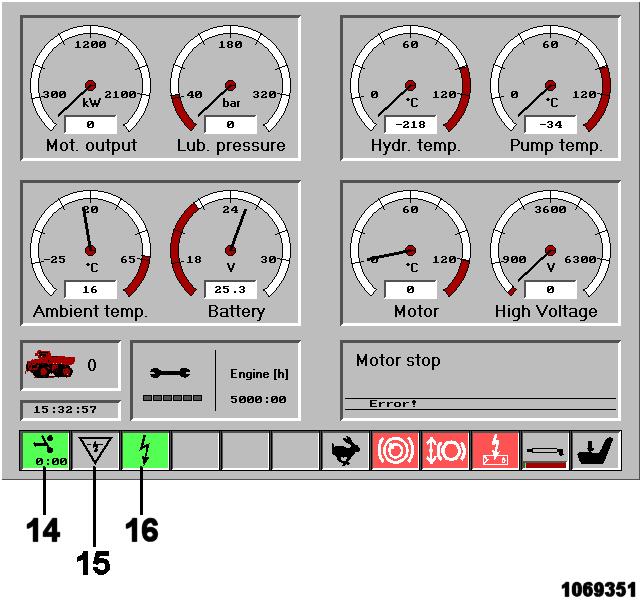
Check telltales (14 and 16, Fig. 2-72:), they must lit up in green colour. If so, electric motor can be switched on (see: "Switching the electric motor on").
If telltales didn`t lit up in green colour, BCS has detected critical operating conditions or faults which prohibit starting the electric motor. BCS indicates this case with telltales (for instance 15 and 16, Fig. 2-72:) as well as by displaying corresponding text.
Switching the electric motor on
Actuate switch-key (51, Fig. 2-73:), the electric motor is switched on.
During starting period the electric motor heavily warm up. Therefore it is not allowed to switch it on and off at will. By means of an electronical time-out circuit (PLC) the electric motor can be switched on only three times a hour (time-out period is 30 minutes).