
34 minute read
Maintenance Interval Schedule (MIS
Ensure that all safety information, warnings, and instructions are read and understood before any operation or any maintenance procedures are performed. The user is responsible for the performance of maintenance, including all adjustments, the use of proper lubricants, fluids, filters, and the replacement of components due to normal wear and aging. Failure to adhere to proper maintenance intervals and procedures may result in diminished performance of the product and/or accelerated wear of components. Use mileage, fuel consumption, service hours, or calendar time, WHICH EVER OCCURS FIRST, in order to determine the maintenance intervals. Products that operate in severe operating conditions may require more frequent maintenance.
Note: Before each consecutive interval is performed, all maintenance from the previous interval must be performed. Perform the following servicing at EVERY interval they occur; for example, the 10 hour and 50 hour service are also performed at the 200 hour interval, etc.
When Required
Boom Line – Install .............................................. 214 Hook Load Line – Install ...................................... 220
Every 10 Service Hours or Daily
Controls for proper operation of boom and hook– Check Boom Stop operation – Check, adjust if required.............................................................. 214 Boom Pivot Pins – Lubricate ................................ 217 Counterweight Cylinder Bearings – Lubricate..... 218 Counterweight Hinge Pins – Lubricate ................ 218 Fairlead Sheave – Lubricate ................................ 219 Hook and Wire Cable (Boom and Hook lines) – Inspect .................................................................. 219 Hydraulic System Oil Level – Check.................... 225 Hoses and fittings for leaks – Check Sheave Block Bearings – Lubricate..................... 226 Pipelayer structures and components for loose bolts, cracks, damage, etc. – Inspect Inspect the hook for any distortion, bends, twists, etc. Inspect the hook for any wear, cracks, nicks, or gouges. Refer to American National Standard Institute ANSI/ASME B30.14 Blocks, and yokes for wear or damage – Inspect Ensure that area between tractor tracks and pipelayer-tractor attachment structures are free from dirt, debris, ice, snow, etc. – Inspect
Every 50 Service Hours or Weekly
Thoroughly check Boom Stop system operation and adjustment, lubricate boom stop valve roller and actuator. Lightly lubricate wire rope with recommended engine or hydraulic oil.
Every 500 Service Hours
Hydraulic System Oil Sample - Obtain ................ 225
Every 500 Service Hours or 3 Months
Hydraulic System Oil Filter – Replace ................. 223 Hydraulic System Case Drain Filter - Replace
Every 2000 Service Hours or 1 Year
Hydraulic System Oil - Change ........................... 221
Accumulator
m WARNING
This system contains high pressure gas. Failure to follow the instructions and warnings could cause an explosion, resulting in possible injury or death. Do not expose to fire. Do not weld. Do not drill. Do not remove any hydraulic system lines, taps or parts until pressure has been relieved. Relieve pressure before discharging. See Operation and Maintenance Manual "Accumulator - Relieving Charge". See Operation and Maintenance Manual "Accumulator" for charging and discharging. See your Dealer for tools and detailed information.
Accumulator must be charged with dry nitrogen (N2) gas by qualified personnel only. The accumulator must be at the same temperature as the surrounding air before being checked or charged. Charge the accumulator depending on the ambient air temperature according to the table below. Access the accumulator to charge from the rear of the tractor, above the tow-winch drive.
283
Illustration 283
Accumulator located behind access panels to right of operator seat.
Table 33
Ambient air temperature [°C (°F)] Accumulator precharge pressure [kPa (psi)± 70 kPa (10 psi)
-7°C (20°F) 3100 kPa (450 psi) -1°C (30°F) 3170 kPa (460 psi) 4°C (40°F) 3240 kPa( 470 psi) 10°C (50°F) 3310 kPa (480 psi) 16°C (60°F) 3375 kPa (490 psi) 21°C (70°F) 3445 kPa (500 psi) 27°C (80°F) 3515 kPa (510 psi) 32°C (90°F) 3580 kPa (520 psi) 38°C (100°F) 3650 kPa (530 psi) 43°C (110°F) 3720 kPa (540 psi) 49°C (120°F) 3790 kPa (550 psi)
Boom Stop Valve Operation and Adjustment
m WARNING
The Boom Stop system stops the boom winch from hauling-in when the boom is vertical, preventing overloading of key machine components. Incorrectly adjusting, or defeating the boom stop valve could result in serious equipment damage, personal injury, or even death. Its operation must be check and verified daily.
284
Illustration 284
Boom stop valve located behind access cover in Left Hand tower.
•To check the operation, boom in slowly taking care not to over tension the boom lines when the boom goes vertical. When the boom is vertical, the boom winch should stop. No increase in tension should occur once the boom comes into contact with the left hand tower. If the boom winch does not stop and continues to increase the cable tension, STOP the operation at once and lower the boom to release the tension. Adjust the boom stop valve as set out below. •Raise the boom vertical so that it is JUST in contact with the tower; the boom kick-out rod is fully retracted into the tower. Do not over tighten the lines to the point that the boom or structures are overly stressed.
•Remove the boom stop valve access panel from the tower.
•Loosen the boom stop valve nuts.
•Move the valve so that it just contacts the boom kick-out rod.
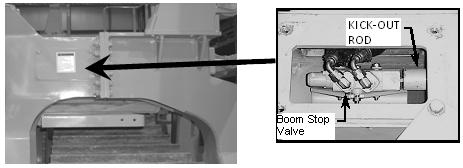
•Move the valve an additional 10 mm (3/8-in) towards the boom so that the valve's piston is fully depressed.
•Tighten the valve in position with the valve nuts.
•Test the boom stop valve to see that it works properly. Lower the boom until the boom stop valve piston is free from the kick-out rod.
•Replace the boom stop valve access panel from the tower.
•Boom in slowly taking care not to over tension the boom lines when the boom goes vertical. When the boom is vertical, the kick-out rod will move the boom stop valve piston in 9.5 mm (3/8 in), and the boom winch should stop with the boom vertical.
No increase in tension should occur once the boom comes into contact with the left hand tower, readjust the boom stop valve as required.
Boom Line – Install
m WARNING
Do not operate or work on this equipment unless you have read and understand the instructions and warnings in the Operation and Maintenance Manual. Failure to follow the instructions or heed the warnings could result in injury or death. Contact your dealer or Vanguard Equipment or visit our website at vanguardequip.com for replacement manuals. Proper care is your responsibility.
m WARNING
Personal injury or death can result from worn wire rope cable. Worn or frayed cable could break causing injury. Check the wire rope cable. If cable is worn or is frayed install new cable. Wear gloves when handling the wire rope cable. Proper care is your responsibility.
NOTICE Make sure that the construction of the wire rope is 6x25 IWRC XIPS (Independent Wire Rope Core, eXtra Improved Plow Steel) USA MADE. Also, the established grade of the wire rope is the improved plow bolt (steel), 26670 kg (58 800 lb) minimum breaking strength.
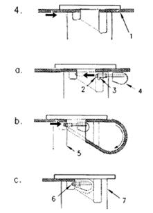
Table 34
SPECIFICATIONS (WIRE ROPE) Boom Line Cable
Boom Length Diameter of Cable Length of Cable
6.1 m (20 ft) 19.05 mm (0.75 inch) 7.3 m (24 ft) 19.05 mm (0.75 inch) 40.2 m (132 ft) 45.7 m (150 ft)
Table 7: Boom line wire rope specifications
1. Lower the boom to the ground and support the boom.
Note: The loaded force in the winch drum must be neutralized before removing the wire rope from a loaded drum.
2. Remove the anchor for the wire rope from the drum for the boom. Remove the old wire rope.
3. Unroll the new wire rope from the spool.
Note: Weld the cable ends in order to prevent fraying.
NOTICE Unroll all of the cable from the spool. Lay the wire rope on a flat surface. Never lift the wire rope off the spool in coils.
285
Illustration 285
nstalling boom line, cable anchor assembly
4. Install the cable (1) into the small slot and through the larger slot in the drum for the boom.
•Make sure that 2 to 4 threads of capscrew (2) are engaged into the cable anchor assembly (4). Start with the capscrew and insert the cable anchor assembly into the longer slot as far as allowed.
•Make sure that the lip of retainer (3) faces the top edge (5) of the small slot in order to hold the retainer in place. Make a loop with the end of the wire rope and insert the end into the slot past the cable anchor assembly.
•Pull the wire rope until the wire rope and anchor assembly are securely seated inside the slot. Tighten the capscrew to a torque (6) of 44 ± 3 N·m (32 ± 2 lb ft).
5. Wind one half of the wire rope on the drum (7.) Wind the wire rope evenly across the drum.
286
Illustration 286
nstalling boom line (A) Wire rope from the winch (B) Detail B
6. Install the wire rope from the winch to sheave (8) in the upper sheave block. Install the wire rope over sheave (8) from the front of the machine toward the rear of the machine.
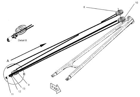
7. Install the wire rope under sheave (9) in the lower sheave block.
8. Install the wire rope over sheave (10) in the upper sheave block.
287
Illustration 287
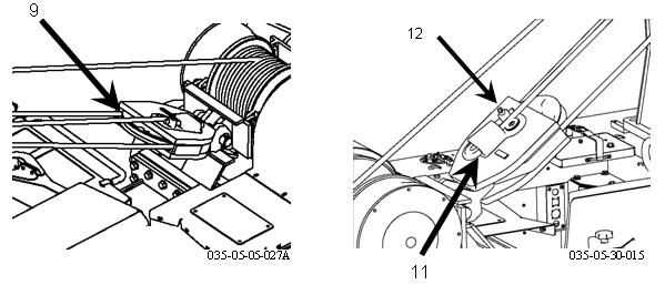
Inserting wire rope into cable anchor
9. Insert the wire rope into the pocket and around the wedge (11). Allow an additional length of cable to form a tail end (six inch minimum). Use a mallet to tap the wedge and the wire rope into the pocket.
10. Insert the tail end of the wire rope through clamp (12). Add a short piece of wire rope through clamp (12) in order to secure the clamp, as needed. Tighten the nuts on the clamp.
Note: Do not clamp the loaded end of the wire rope and the tail end of the wire rope together.

11. Apply the first load in order to seat wedge (11).
Boom Pivot Pins – Lubricate
The grease fittings for lubricating the boom pivot pins are located on the left side of the machine.
There is one grease fitting for each pin. The grease fittings are located on the end of the pin on the outside face of the boom.
288
Illustration 288
Boom pivot pins, grease fittings
Lubricate the boom pivot pins through the two fittings.
Counterweight Cylinder Bearings – Lubricate
289

Counterweight Hinge Pins - Lubricate
m WARNING
Use a stable work platform placed in a secure location when lubricating the counterweight hinge pins. If a secure location is not available, use the appropriate safety equipment to prevent falling off of the machine. Failure to work from a secure location may result in injury or death from a slip or a fall.
Illustration 289
Counterweight cylinder bearings fittings location Lubricate the six pins through the grease fittings. There are three grease fittings that face toward the front of the machine and there are three grease fittings that face toward the rear of the machine.
291
290

Illustration 290

Counterweight cylinder bearings location
1. Extend the counterweight and lock the counterweight into position.
Refer to the Operation and Maintenance Manual, “Counterweight Lock Lever” for the proper procedure to lock the counterweight into position.
2. Lubricate the upper grease fitting that is located in the head end of the cylinder.
3. Lubricate the grease fitting that is located in the rod end of the cylinder.
4. Follow the procedure to unlock the counterweight and retract the counterweight.
5. Follow the procedure to unlock the counterweight and retract the counterweight.
There are two grease fittings for the counterweight cylinder.
Illustration 291
Counterweight hinge pins located right side of machine
Lubricate the two lower pins through the grease fittings.
Note: If the counterweight is fully extended, install the counterweight lock lever in order to lubricate the counterweight hinge pins. Refer to Operation and Maintenance Manual, “Counterweight Lock Lever” for more details.
292
Illustration 292

Counterweight hinge pins lubrication points
Fairlead Sheave – Lubricate
293
Illustration 293

Fairlead sheave lubrication points
Lubricate one fitting in the lower sheave and lubricate one fitting in the upper pin.
Hook and Wire Cable – Inspect
Inspect the Hook
Inspect the hook frequently. The inspections should include observation of the hook during operation of the hook. A designated person determines if the conditions that are found during the inspections constitute a hazard. The designated person will determine if a more detailed inspection is required.
•Inspect the hook for any distortion such as bends in the hook or twists in the hook.
•Inspect the hook for any wear.
•Inspect the hook for cracks, nicks, or gouges.
•If a latch is provided, inspect the latch. Make sure that the latch engages properly. Inspect the latch for any damage. Make sure that the latch is not malfunctioning.
•Inspect the hook assembly and the means for securing the hook assembly.
•For additional information on the proper maintenance and on the proper inspection of hooks, refer to "American National Standard
Institute ANSI/ASME B30.14".
Inspect Wire Cable - Boom and Hook lines
Make a visual inspection of all running cables that are in continuous use. Make the inspection of the running cables on a daily basis before the machine is placed in operation. Inspect all of the cables on a monthly basis.
All inspections shall be performed by a designated person. Keep a dated report of the condition of the cable on file in a location that is available to designated personnel. Perform a close inspection of the sections of the cable that are normally hidden during the visual inspection and the maintenance inspection. (This includes the sections of the cable that pass over the sheaves.) These points are the sections of the cable that are most likely to fail.
Note any deterioration that results in a notable loss of the original strength. (See the conditions that are described below.) Determine if further use of the cable will constitute a hazard.
Inspect the cable on a daily basis for the following conditions:
•Inspect the cable for a reduction in the diameter of the cable below the nominal diameter. A loss of support in the cored wire of the cable may be caused by internal corrosion, external corrosion, or wear of the outside wires.
•Inspect the cable for broken outside wires. Check for the degree of distribution of the broken outside wires. Check for the concentration of outside broken wires.
•Inspect the cable for worn outside wires.
•Inspect the cable for corroded wires and for broken wires at the connection on the wire cable end.
•Inspect the cable end for connections that are corroded, cracked, bent, worn, or improperly installed.
•Inspect the cable for sections that are crushed or kinked and for any loose wire strands.
Excessive wear or broken wires may occur in sections of the cable that are in contact with saddles, equalizer sheaves, or other sheaves. Excessive wear or broken wires can also occur when cable travel is limited. Take care to inspect the ropes at these locations.
When a machine is shutdown for a month or more, inspect all of the cables thoroughly. When a side boom machine has been in storage for a month or more inspect all of the cables thoroughly. The inspection should be completed before the machine is returned to operation.
The inspection should be for all types of deterioration. The inspection should be performed by a designated person or by an authorized person. The authorized person's approval is required for further use of the cable.
A dated report on the condition of the cable should be kept on file.
Take care in the inspection of cable that is resistant to rotation.
Any new poured socket or swaged socket assembly that is used as a standing cable (guy) shall be proof tested. Test the cable to the lift capacity of the side boom machine or to the manufacturer's recommendation.
Never give the cable a rating that is greater than 50 percent of the wire rope's nominal strength or of the structural strand's nominal strength. Note: For additional information on the proper maintenance and on inspection of the cable, refer to "American National Standards Institute ANSI/ASME B30.14".
Hook Load Line – Install
m WARNING
Do not operate or work on this equipment unless you have read and understand the instructions and warnings in the Operation and maintenance Manual. Failure to follow the instructions or heed the warnings could result in injury or death. Proper care is your responsibility.
m WARNING
Personal injury or death can result from worn wire rope cable. Worn or frayed cable could break causing injury. Check the wire rope cable. If cable is worn or is frayed install new cable. Wear gloves when handling the wire rope cable.
NOTICE Make sure that the construction of the wire rope is 6x25 IWRC XIPS (Independent Wire Rope Core, eXtra Improved Plow Steel) USA MADE. Also, the established grade of the wire rope is the improved plow bolt (steel), 26670 kg (58 800 lb) minimum breaking strength.
Table 35
SPECIFICATIONS (WIRE ROPE) Hook Load Line Cable Boom Length Diameter Length
6.1 m (20 ft) 19.05 mm (0.75 inch) 50.3 m (165 ft) 7.3 m (24 ft) 19.05 mm (0.75 inch) 57.3 m (188 ft)
1. Lower the boom to the horizontal position.
2. Remove the anchor for the wire rope from the drum for the hook. Remove the old wire rope.
3. Unroll the new wire rope from the spool.
Note: Weld the cable ends in order to prevent fraying.
NOTICE Unroll all of the cable from the spool. Lay the wire rope on a flat surface. Never lift the wire rope off the spool in coils.
294 295
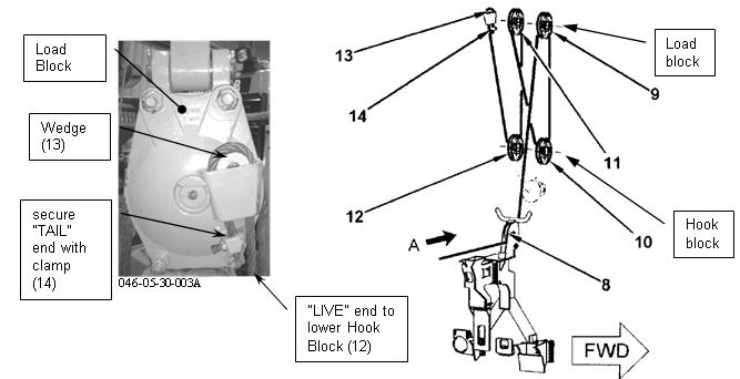
Illustration 294

Installing hook load line, cable anchor assembly
1. Install the cable (1) into the small slot and through the larger slot in the drum for the hook load line.
•Make sure that 2 to 4 threads of capscrew (2) are engaged into the cable anchor assembly (4). Start with the capscrew and insert the cable anchor assembly into the longer slot as far as allowed.
•Make sure that the lip of retainer (3) faces the top edge (5) of the small slot in order to hold the retainer in place. Make a loop with the cable end and insert the cable end into the slot past the cable anchor assembly.
•Pull the cable until the cable and anchor assembly are securely seated inside the slot.
Tighten the capscrew to a torque (6) of 44 ± 3
Nm (32 ± 2 lb ft).
2. Wind one half of the cable evenly across the load drum (7).
Illustration 295
Installing hook load line (A) Wire rope from the winch.
3. Install the hook load line from the winch drum onto the sheave blocks in the following manner:
•Install the cable for the hook winch from the winch drum to fairlead sheave (8).
Note: The cable for the hook winch should go over upper sheave (9) which is toward the front of the machine. Anchor the cable for the hook winch toward the rear of the machine.
•Install the cable over upper sheave (9).
•Install the cable under lower sheave (10).
•Install the cable over upper sheave (11).
•Install the cable under lower sheave (12).
•Insert the cable into the pocket and around wedge (13). Allow an additional length of cable to form a tail end (six inch minimum). Use a mallet to tap the wedge and the wire rope into the pocket.
•Insert the tail end of the wire rope through clamp (14). Add a short piece of wire rope through clamp (14) in order to secure the clamp, as needed. Tighten the nuts on the clamp.
•Pull the cable until the line is tight in order to seat wedge (13). Lift the lower block above the ground.
•Raise the boom.
Hydraulic System Oil - Change
Refer to the specific tractor Operation and Maintenance Manual "Hydraulic System Oil - Change" for complete requirements and procedures.
m WARNING
At operating temperature, the hydraulic tank is hot and under pressure. Hot oil and components can cause personal injury. Do not allow hot oil or components to contact skin. Remove the filler cap only when the engine is stopped, and the filler cap is cool enough to touch with your bare hand. Remove the filler cap slowly in order to relieve pressure.
NOTICE Care must be taken to ensure that fluids are contained during performance of inspection, maintenance, testing, adjusting and repair of the product. Be prepared to collect the fluid with suitable containers before opening any compartment or disassembling and component containing fluids.
Dispose of all fluids according to local regulations and mandates.
Operate the machine in order to warm the oil.
Park the machine on level ground. Engage the parking brake and stop the engine.
296 297

Illustration 296

Hydraulic tank filler cap
Remove the hydraulic tank filler cap (1) slowly in order to relieve any pressure.
1. Wash the filler strainer and the filler cap in a clean nonflammable solvent.
2. Remove oil drain plug (2).
3. Attach a hose to a 1 inch NPT pipe nipple. This 1 inch NPT pipe nipple should have a length of 100 mm (4 inch). 4. Install the pipe nipple into the drain plug opening.
5. Rotate the pipe nipple clockwise in order to open the internal drain valve. Allow the oil to drain into a suitable container.
6. Remove the pipe nipple. The valve for the hydraulic tank will close.
7. Clean drain plug (2) and install drain plug (2).
Tighten drain plug (2) to a torque of 68 ± 7 Nm (50 ± 5 lb ft).
8. See the Operation and Maintenance Manual,
Maintenance and Lubrication section, “Hydraulic
System Oil Filter – Replace”. Change the hydraulic system filter (4).
9. See the Operation and Maintenance Manual,
Maintenance and Lubrication section, “Hydraulic
System Case Drain Filter – Replace”. Change the hydraulic system case drain filter (5).
10. Install the filler strainer.
Illustration 297
Winch Drains and Case Drain Filter
11. Drain the oil from both of the winches (6 & 7) into a suitable container.
12. See the Operation and Maintenance Manual,
“Capacities (Refill) in order to determine the amount of hydraulic oil that is needed to fill the hydraulic oil tank. Fill the hydraulic oil tank.
13. Inspect the filler cap gasket. Install a new gasket if damage or wear is evident. Install the filler cap.
14. Start the engine. Run the engine for a few minutes. Check for leaks.
15. Maintain the oil level to the “FULL” mark in sight gauge (3). Add oil, if necessary. Stop the engine.
Hydraulic System Oil Filter - Replace
m WARNING
At operating temperature, the hydraulic tank is hot and under pressure. Hot oil and components can cause personal injury. Do not allow hot oil or components to contact skin. Remove the filler cap only when the engine is stopped, and the filler cap is cool enough to touch with your bare hand. Remove the filler cap slowly in order to relieve pressure.
1. Slowly remove the hydraulic tank filler cap in order to relieve the system pressure.
2. Open the access door that is located on the right side of the machine next to the filler cap.
298
Illustration 298
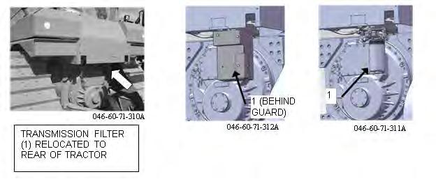
Filter locations
299

Illustration 299

Filter locations
300
Illustration 300
Filter location (1) Transmission oil filter (2) Hydraulic system filter (3) Hydraulic Tank filler cap (4) Case drain filter pipelayer
3. Remove filter (1, 2, and 4).
Note: Remove case drain hydraulic filter (1). Discard the used filter. Filter (1) must be removed for access to hydraulic system filter (2). Replace both of the filters at the same time.
4. Inspect the seal on the filter housings for filter (1, 2, and 4). If the seals are damaged or worn, install new seals. Install a new filter element into the filter housing for (1, 2, and 4).
Hydraulic System Oil Level – Check
m WARNING
At operating temperature, the hydraulic tank is hot and under pressure. Hot oil and components can cause personal injury. Do not allow hot oil or components to contact skin. Remove the filler cap only when the engine is stopped, and the filler cap is cool enough to touch with your bare hand. Remove the filler cap slowly in order to relieve pressure.
The hydraulic tank is on the right rear corner of the machine.
301
Illustration 301

Hydraulic Tank
1. The counterweight should be fully retracted when you check the oil level.
2. Maintain the oil level to the “FULL” mark in sight gauge (1). 3. If the hydraulic system requires additional hydraulic oil, remove filler cap (2) and add oil.
Clean filler cap (2) and install filler cap (2).
Hydraulic System Oil Sampling
Refer to the tractor’s operation and maintenance manual for the specific procedures regarding Hydraulic System Sampling.
Oil Filter Inspection
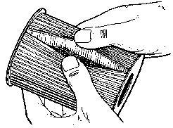
302
Illustration 302
Oil filter.
Use a Filter Cutter - CAT# 4C-5084, or similar to cut the filter element open. Spread apart the pleats and inspect the element for metal and other debris. An excessive amount of debris in the filter element can indicate a possible failure.
If metals are found in the filter element, a magnet can be used to differentiate between ferrous metals and nonferrous metals. Ferrous metals would indicate wear on steel parts and on cast iron parts. Non ferrous metals would indicate wear of the brass or aluminum part of the hydraulics such as main bearings, pump sleeves, etc.
Small amounts of debris may be found in the filter element. This could be caused by friction and normal wear. Consult your Caterpillar dealer in order to arrange for further analysis if an excessive amount of debris is found.
Using an oil filter element that is not recommended by Caterpillar could result in severe damage. This could result in larger particles in unfiltered oil. These particles could enter the system and cause damage.
Sheave Block Bearing – Lubricate
303
Tractor Maintenance
Refer to the tractor’s operation and maintenance manual for the specific procedures regarding complete Tractor Maintenance.
Illustration 303
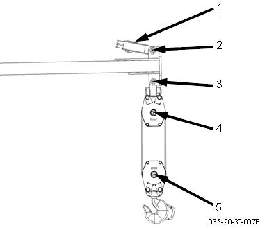
Rigging Grease Nipples
1. Lubricate (1) in the luff block.
304
Illustration 304

Rigging Grease Nipples - Tail Block
2. Lubricate fitting in the pins for boom luff block (2 & 3) and load sheave block.
3. Lubricate pin (4) in load sheave block and the pin (5) in the hook sheave block.
4. Lubricate pin (6) on tail block.
IndexA
Accumulator - Relieving Charge ......................... 202 Action Lamp .......................................................... 66 Active Faults ......................................................... 80 Additional Messages ............................................. 14 Additional Operator Controls ................................. 62 Adjustable Armrests .............................................. 51 Adjusting the Angle of the Back of the Seat .......... 44 Adjusting the Bottom Seat Cushion ...................... 44 Adjusting the Fore and Aft Position of the Seat .... 44 Adjusting the Height of the Seat ........................... 45 Adjusting the Lumbar Support .............................. 46 Adjusting the Seat ................................................. 44 Adjustments ........................................................ 100 ARD Spark Plug - Replace ................................. 125 Asbestos Information ............................................ 19 Auto Kickdown Mode ............................................ 58
B
Backup Alarm ........................................................ 94 Backup Alarm - Test ........................................... 125 Batteries ................................................................ 20 Battery - Inspect .................................................. 126 Battery and Battery Cables ................................... 22 Battery Disconnect Switch .............................. 63, 95 Before Operation ............................. 25, 42, 187, 197 Before Starting Engine .......................................... 25 Belt - Inspect/Replace ......................................... 126 Bidirectional Shift Mode ........................................ 54 Biodiesel ............................................................. 119 Bolt Torque for Track Shoes ............................... 168 Boom Control ...................................................... 202 Boom Stop Operation and Adjustment - Do Not Operate ............................................................... 185 Boom Stop Valve ................................................ 202 Brake Engagement ............................................. 110 Brake Release .................................................... 110 Brakes, Indicators and Gauges - Test ................ 127 Braking System (Test) ........................................ 127 Burn Prevention .................................................... 20
C
Cab Filter (Fresh Air) - Clean/Inspect/Replace (If Equipped) ............................................................ 128 Cab Filter (Recirculation) - Clean/Inspect/Replace (If Equipped) ............................................................ 129 California Proposition 65 Warning .......................... 5 Capacities (Refill) ................................................ 120 Caterpillar Product Identification Number ............... 5 CE Mark ................................................................ 37 Certification ........................................................... 37 Certified Engine Maintenance ................................. 5 Change the Hydraulic Oil .................................... 156 Changing Direction and Speed ............................. 95 Checking the Battery Disconnect System ............. 96 Circuit Breakers .................................................. 155 Commercial Oils ................................................. 155 Components ....................................................... 193 Compressed Recoil Spring ................................... 14 Connection for the Pump .................................... 109 Connection of Brake Release Pump ................... 107 Containing Fluid Spillage ...................................... 18 Coolant ................................................................. 20 Coolant Information ............................................ 119 Cooling System Coolant (ELC) - Change ........... 129 Cooling System Coolant Extender (ELC) - Add .. 131 Cooling System Coolant Level - Check .............. 132 Cooling System Coolant Sample (Level 1) - Obtain ................................................................. 133 Cooling System Coolant Sample (Level 2) - Obtain ................................................................. 134 Cooling System Water Temperature Regulator - Replace ............................................................... 135 Counterweight Control ........................................ 202 Counterweight Control-Lockout Lever ................ 202 Counterweight Crushing Hazard ......................... 186 Counterweight Lock Lever .................................. 203 Counterweight Lock Lever Thrown or Flying Objects - Full Body Exposure ............................................. 187 Crushing Prevention and Cutting Prevention ........ 19
D
Daily Checks ....................................................... 198 Daily Inspection .................................................... 43 Data Broadcasts ................................................... 87 Decelerator Pedal ................................................. 53 Declaration of Conformity ..................................... 40 Decommissioning and Disposal .......................... 179 Delayed Engine Shut Down .......................... 72, 101 Delayed Engine Shutdown ................................... 65 Diagnostic and Event Codes ................................ 80 Diesel Fuel Recommendations ........................... 118 Diesel Particulate Filter - Clean/Replace ............ 136 Diesel Particulate Filter Regeneration .................. 63 Differential Steering Control .................................. 51 Digital Display Window ......................................... 69 Display Module ..................................................... 73 Display Readout ................................................... 70 Display Settings .................................................... 78 Dispose of Waste Properly ................................... 19 Do Not Operate ............................................... 8, 182 Do Not Weld on the FOPS .................................... 11 Do Not Weld on the ROPS ..................................... 9 Duration Timer ...................................................... 53
E
ECM Summary ..................................................... 80 Ecology Drains .................................................... 120 Electrical Connector Location ............................... 83 Electrical Power Lines .......................... 27, 183, 190 Electrical Shock Hazard ........................................ 10 Electrical Storm Injury Prevention ......................... 25 Emergency Shutdown Override ............................ 73
Emissions Certification Film ..................................41 Emissions Warranty Information ......................... 177 Engine Air Filter Primary and/or Secondary Element - Clean/Replace .................................................... 136 Engine Air Precleaner - Clean ............................ 138 Engine and Machine Warm-Up ............................. 98 Engine Fan Reverse Switch .................................. 60 Engine Idle Shutdown ........................................... 73 Engine Monitoring Mode ....................................... 72 Engine Oil ........................................................... 113 Engine Oil and Filter - Change ............................ 139 Engine Oil Level - Check .................................... 138 Engine Oil Sample - Obtain ................................ 139 Engine Start Switch ............................................... 58 Engine Starting ............................................... 25, 97 Engine Starting (Alternate Methods) ................... 111 Engine Starting with Jump Start Cables ............. 111 Engine Stopping .................................................... 29 Engine Valve Lash - Check/Adjust ...................... 142 Equalizer Bar Center Pin - Lubricate .................. 142 Equalizer Bar End Pins Oil Level - Check ........... 143 Equipment Lowering with Engine Stopped .............................................................. 29, 191, 205 Ether ..................................................................... 23 Ether Starting Aid .................................................. 97 Ether Starting Aid Cylinder - Replace ................. 143 Every 10 Service Hours or Daily ......................... 123 Every 1000 Service Hours or 6 Months .............. 123 Every 12 000 Service Hours or 6 Years .............. 124 Every 2000 Service Hours .................................. 124 Every 2000 Service Hours or 1 Year .................. 124 Every 2000 Service Hours or 2 Years ................. 124 Every 250 Service Hours or 3 Months ................ 123 Every 250 Service Hours or Monthly .................. 123 Every 2500 Service Hours .................................. 124 Every 3 Years After Date of Installation or Every 5 Years After Date of Manufacture ........................ 124 Every 4500 Service Hours .................................. 124 Every 50 Service Hours or Weekly ..................... 123 Every 500 Service Hours .................................... 123 Every 500 Service Hours or 3 Months ................ 123 Every 5000 Service Hours .................................. 124 Every 6000 Service Hours or 3 Years ................. 124 Every Year .......................................................... 124 Exhaust ................................................................. 19 Exhaust Gas Recirculation Cooler ........................ 20 Extended Life Coolant (ELC) Extender ............... 131 Extension for the Back of the Seat ........................ 47 Extension of the Seat Belt ..................................... 49
F
Fastening The Seat Belt ................................. 48, 49 Final Drive Oil - Change ...................................... 144 Final Drive Oil Level - Check .............................. 144 Final Drive Oil Sample - Obtain .......................... 145 Fire Extinguisher ................................................... 23 Fire Extinguisher Location .................................... 24 Fire Prevention and Explosion Prevention ............ 21 Fire Safety ............................................................. 24 Fluid Penetration ................................................... 18 Foreward ................................................................. 4 Free Fall Active - Do Not Operate ...................... 184 Front Idler Position - Check ................................ 145 Fuel Additives ..................................................... 119 Fuel Priming Pump - Replace ............................. 147 Fuel System - Prime ........................................... 147 Fuel System Primary Filter/Water Separator - Drain ................................................................... 148 Fuel System Secondary Filters - Replace .......... 148 Fuel System Water Separator Element - Replace ............................................................... 149 Fuel Tank Cap Filter and Strainer - Replace/ Clean .................................................................. 150 Fuel Tank Water and Sediment - Drain .............. 151 Fumes Disposal Filter Element - Replace .......... 152 Functional Test ..................................................... 66 Functional Test of the Monitoring System Display ................................................................ 127 Fuses .................................................................. 153 Fuses and Circuit Breakers - Replace/Reset ...... 152
G
Gauges ................................................................. 66 Gauges and Indicators .......................................... 53 General ................................................................. 21 General Hazard Information ................................. 17 General Information ...................................... 34, 193 Grease ................................................................ 117 Ground Level Service Center ............................... 62 Guards ................................................................ 192 Guards (Operator Protection) ............................... 32 Guidelines for Reducing Vibration Levels on Earthmoving Equipment ....................................... 31
H
Hand/Arm Vibration Level ..................................... 30 High Pressure Cylinder ......................................... 13 High Pressure Recoil Spring ................................. 13 Hook Control ....................................................... 201 Horn ...................................................................... 62 Horn location moved ........................................... 203 Hot Fluid Under Pressure ..................................... 12 Hydraulic Accumulator ................................ 183, 184 Hydraulic Lockout Control ..................................... 61 Hydraulic Oil Temperature .................................. 199 Hydraulic System Accumulator ............................. 12 Hydraulic System Oil - Change ........................... 155 Hydraulic System Oil Filter (Pilot) - Replace ....... 157 Hydraulic System Oil Filters - Replace ............... 158 Hydraulic System Oil Level - Check ................... 160 Hydraulic System Oil Sample - Obtain ............... 160 Hydraulic Systems .............................................. 114 Hydraulic Tank .................................................... 158
I
Idling .....................................................................98 Idling the Engine for Extended Periods ............... 102 Implement Settings ............................................... 78 Improper Connections for Jump Start Cables ....... 10 Improper Maintenance Procedures ..................... 122 Inhalation .............................................................. 19 Installing the Spark Plug ..................................... 125 Intended Use ....................................................... 195 ISO Symbols ......................................................... 38
J
Joystick Control ..................................................... 61
K
Key Off Regeneration ........................................... 65
L
Leaving the Machine ........................................... 102 Lengthening the Seat Belt ..................................... 48 Lift Control ............................................................. 61 Lift Cylinder Yoke Bearings - Lubricate ............... 161 Lifting and Tying Down the Machine ................... 104 Lifting Capacities ................................... 27, 189, 195 Light Switches ....................................................... 53 Limitations on Lifting Loads That Exceed the Working Range ........................................................... 27, 189 Limp Home Mode (Implement) ............................. 81 Lines, Tubes, and Hoses ...................................... 23 Listing of Abbreviations and Terms ....................... 83 Literature Information .............................................. 4 Loose Track Adjustment ..................................... 167 Low Idling Speed .................................................. 99 Lubricant Viscosities (Fluids Recommendations) 113 Lubricant Viscosities and Refill Capacities ......... 113 Lubricants ........................................................... 155
M
Machine Capacity ................................................... 5 Machine Description ............................................... 4 Machine Operating Temperature Range ...... 26, 189 Machine Operation .................................. 26, 44, 189 Machine Security .................................................. 87 Machine Settings .................................................. 78 Machine Start-up ................................................... 74 Machine Status ..................................................... 82 Main Menu ............................................................ 74 Maintenance ........................................................... 4 Maintenance Interval Schedule ........................... 123 Maintenance Intervals ............................................. 5 Maintenance Section (D6T LGP (OEM)) ............ 113 Maintenance Support .......................................... 121 Menu for the Operator Profile ............................... 74 Mirror ..................................................................... 53 Modes of Regeneration ......................................... 64 Monitoring System ................................................ 66 Monitoring System Display ............................. 53, 70 Mounting and Dismounting ........................... 42, 197 MVP Switch .......................................................... 54
O
Oil Filter - Inspect ................................................ 161 Oils ........................................................................ 20 Onboard Display ................................................... 55 Operating The Machine ........................................ 94 Operation .................................................. 4, 26, 189 Operation in a Blast Site ....................................... 87 Operation Information ........................................... 94 Operation Section (D6T LGP (OEM)) ................... 42 Operation Section (Pipelayer Attachment Kit) .... 197 Operator Controls ................................................. 50 Operator in Seat (Sensor) ..................................... 68 Operator Preferences ........................................... 75 Operator Profile .................................................... 74 Operator Seat ....................................................... 68 Operator Station ................................................... 32 Other Guards ........................................................ 33
P
Parking .................................................. 28, 101, 190 Password Entry Screen ........................................ 77 Performance Screens ........................................... 71 Pipelayer Operation ............................................ 200 Pivot Shaft Oil Level - Check .............................. 162 Plate Locations and Film Locations ...................... 36 Power Train Settings ............................................ 77 Pressurized Air and Water .................................... 18 Primary Filter ...................................................... 136 Procedure for Changing the Engine Oil and Filter .................................................................... 140 Product Information Section (D6T LGP (OEM)) .... 34 Product Information Section (Pipelayer Attachment Kit) ...................................................................... 193 Product Link .................................................... 14, 86
R
Radiator Core - Clean ......................................... 162 Radiator Pressure Cap - Clean/Replace ............. 162 Recoil Spring Compartment Oil Level - Check ... 163 Reference Information Section (D6T LGP (OEM)) ................................................................ 178 Reference Materials ............................................ 178 Refrigerant Dryer - Replace ................................ 164 Regeneration .................................................. 21, 63 Regeneration Indicators .................................. 59, 63 Regeneration Switch ....................................... 59, 63 Regeneration System Warning Indicators ............ 64 Regulatory Compliance ........................................ 88 Releasing The Seat Belt ....................................... 49 Relief Valve Setting ............................................ 108 Removing the Spark Plug ................................... 125
Reporting a Problem .............................................83 Restricted Visibility ................................................ 26 Restrictions to Application and Configuration 34, 195 Rollover Protective Structure (ROPS) - Inspect .. 165 Rollover Protective Structure (ROPS), Falling Object Protective Structure (FOPS) or Tip Over Protection Structure (TOPS ................................................... 33 Rotating Shaft ....................................................... 11 Running Engine .................................................. 107
S
S·O·S Information ............................................... 120 Safety ...................................................................... 4 Safety Messages .................................................... 6 Safety Messages - 72H Pipelayer ....................... 180 Safety Section (D6T LGP (OEM)) ........................... 6 Safety Section (Pipelayer Attachment Kit) .......... 180 Seat ....................................................................... 44 Seat Belt ..................................................... 9, 47, 48 Seat Belt - Inspect ............................................... 165 Seat Belt - Replace ............................................. 165 Seat Belt Adjustment for Non-Retractable Seat Belts ...................................................................... 48 Seat Belt Adjustment for Retractable Seat Belts .. 49 Secondary Filter .................................................. 137 Selecting the Viscosity ........................................ 113 Service Brake Control ........................................... 53 Service Hour Meter ............................................... 63 Service Menu ........................................................ 79 Settings Menu ....................................................... 76 Severe Environmental Factors ............................ 121 Severe Operating Conditions .............................. 121 Severe Service Application ................................. 121 Shipping the Machine ................................. 104, 206 Shortening the Seat Belt ....................................... 48 Slope Operation ............................................ 28, 190 Soot Level Monitoring ........................................... 63 Sound Information and Vibration Information ...................................................................... 29, 191 Sound Level Information ............................... 29, 191 Sound Level Information for Machines in European Union Countries and in Countries that Adopt the “EU Directives” ............................................................. 29 Sound Performance for Machines that are Offered in European Union Countries and in Countries that Adopt the EU Directives ...................................... 191 Sources ................................................................. 32 Special Applications ............................................ 116 Special Lubricants ............................................... 117 Specifications ................................................ 34, 194 Speed Range Control ........................................... 54 Speed/Lockout Control Lever ............................. 200 Speed/Lockout Control Lock ............................... 201 Status Indicators ................................................... 68 Steering Charge Filter ......................................... 159 Steering Limp Home Mode ................................... 81 Stopped Engine or Drive Line Defect .................. 107 Stopping the Engine ............................................ 101 Stopping the Engine if an Electrical Malfunction Occurs ................................................................. 102 Stopping the Machine ......................................... 101 Storage for the Operation and Maintenance Manual ................................................................. 47 Structure certification (ROPS) .............................. 37 Subsequent Engine Starting Procedures .............. 98
T
Tachometer ........................................................... 69 The European Union Physical Agents (Vibration) Directive 2002/44/EC .................................... 30, 192 Throttle Control Switch ......................................... 60 Throttle control switch & Operator Heater switch .................................................................. 203 Tilt Control ............................................................ 62 Tipover Hazard ................................................... 185 Tool Storage Area ................................................. 43 Torque Converter Scavenge Screen - Clean ...... 166 Totals Display (Menu) ........................................... 82 Towing Information ............................................. 106 Towing the Machine ............................................ 106 Track - Check/Adjust .......................................... 167 Track Information .................................................. 24 Track Pins - Inspect ............................................ 168 Track Roller Frame Guides - Inspect .................. 168 Tracks ................................................................. 100 Tractor Operation ................................................ 199 Transmission and Axles ...................................... 115 Transmission Breather - Clean/Replace ............. 170 Transmission Control ............................................ 52 Transmission Magnetic Screen - Clean .............. 170 Transmission Oil - Change ................................. 171 Transmission Oil Filter - Replace ........................ 172 Transmission Oil Level - Check .......................... 173 Transmission Scavenge Screen - Clean ............ 173 Transmission System Oil Sample - Obtain ......... 174 Transportation Information .......................... 104, 206 Trapped Pressure ................................................. 18
U
Use of Jump Start Cables ................................... 111
V
Vibration Data for Track-Type Tractors ................ 30 Visibility Information ...................................... 25, 187
W
Warning Categories .............................................. 69 Warranty Information .......................................... 177 Warranty Section (D6T LGP (OEM)) .................. 177 Weight Adjustment ................................................ 46 Welding on Machines and Engines with Electronic Controls .............................................................. 121 When Required ................................................... 123 Whole Body Vibration Level .................................. 30
Window Washer Reservoir - Fill ..........................174 Window Wipers - Inspect/Replace ...................... 175 Windows - Clean ................................................. 175 Wiring .................................................................... 22


