50 minute read
ACCIDENT PREVENTION REGULATIONS FOR ELECTRICALLY POWERED EXCAVATORS

from Cat 6060 AC, 6060 AC FS Hydraulic Shovel Operation and Maintenance Manual BI015416 - PDF DOWNLOAD

The safety and accident-prevention regulations valid in the respective country must be observed.
The following requirements are based on extracts from the German accident prevention regulations "Electrical Systems (BGV A3)".
The installation, modification and repair of the electromechanical component of electrical systems and components must be delegated only to qualified electricians or firms employing such experts.
A "qualified electrician" in the context of this regulation is a person who, on the basis of specialized training, know-how and experience as well as knowledge of the relevant regulations, is in a position to judge the extent of the work assigned to him and to recognize any potential hazards.
The machine owner/contractor must inform all persons working on electrical installations and components or in the vicinity of components conducting electricity during operation, or who are responsible for the operation of electrical systems, of the potential danger of electricity and must instruct them on the accident prevention regulations relevant to their work. Instruction in safety measures is to be repeated at intervals appropriate to the operating conditions. If necessary, special working regulations must be displayed.
The excavator and its electrical systems must be adequately protected against other potential hazards of electricity, e.g. fire and explosion.
Electrical systems and components must be protected against electric shock in the case of a fault, e.g. short circuit to exposed conductive part.
Any parts of the electrical system conducting current when in operation must be housed in lock-up switchgear cabinets. Hazard warning signs are displayed on these lock-up cabinets.
Voltage Hazard
The switchgear cabinets must be secured against unauthorized opening. The key must be kept by the electrician in charge.
Electrical systems and components must not be used unless they comply with the operational and local safety requirements. They must be in an orderly state and must be kept in such a state. Any defects or malfunctions occurring in electrical systems or components must be reported to the electrician in charge.
Before switching on any systems, the excavator operator must check that no one is working on the machine or its electrical systems.
The heavy-duty power cable must never be driven over, buried or ripped away. The excavator equipment must never be set down on the power cable. When the excavator is being moved, the cable must never be pulled or dragged over the ground. Whenever work is being carried out on electrically powered excavators, the general rules of engineering - especially those concerning low and medium voltage - must be observed. Regulations such as those issued by the German VDE, e.g. specification VDE 0100, should be observed. Observe all the related laws and rules in your state or country.
Before commencing any work on electrical systems and components, the electrician in charge (or an electrician appointed by him) must switch the power off all circuits and lock them in the OFF state as follows:
Switch voltage OFF all systems.
Check with voltage detectors that all systems are voltage-free.
Lock switches/systems to prevent them from being switched ON.
The above procedures must be carried out in the given sequence.
The machine contractor must provide all the necessary protective equipment and adopt the necessary safety procedures. He must ensure that the safety equipment is used and the safety procedures observed.
The excavator operator and all personnel working on the excavator must use the protective equipment and carry out the specified safety procedures. It is absolutely forbidden to work on any systems or components while they are conducting current. Fatal injury can occur.
If work has to be done in special cases on systems or components conducting current, appropriate safety measures must be taken. Work must not be done on "live" systems and components except by the electrician in charge. The machine contractor must also be notified.
The excavator and its electrical systems must not be switched on again until the above safety procedures have been cancelled and all working areas are prepared for the resumption of operations. Start-up can be ordered only by the person in charge (qualified electrician). Time-based switch-on agreements are absolutely forbidden.
Safety instructions for excavators with electric motor
Before carrying out any maintenance and repair work on the electrical system, the following precautions must be taken:
In the transformer station
Switch off the supply voltage
Lock the safety device preventing switch-on; apply a warning sign
Check that the electrical system is off circuit and dead
Connect to earth and short-circuit
Protect adjacent and live parts against accidental contact
On the excavator
Switch off the switch-disconnector
Lock the safety device preventing switch-on; apply a warning sign
Remove the cover
Check that the electrical system is off circuit and dead
Connect to earth and short-circuit
Slide the partition into the disconnector housing
Fire And Explosion Hazard
Prior to commencing work, obtain informationon the national and corporate rules for the prevention of accidents. Pay particular attention to hazards caused by combustible and easily flammable substances.on the safe handling of the fire extinguishers to be used.
Avoid smoking and open fire on, next to and below the excavator.
Combustible and easily flammable substances or liquids increase the fire and explosion hazard. Do not store or handle any flammable substances during operation.
Clean the excavator thoroughly, if possible, with a steam jet (rubber parts and electric components with compressed air - refer to information label), when, for example, oil, grease, fuel or cleaner was spilled.
Such substances may spontaneously ignite if they get into the vicinity of hot units or objects such as turbo superchargers.
Even battery gases can ignite in open flames or fire. Avoid parking the excavator in places where
combustible substances such as coal dust or tar are present.
open or smouldering fire may occur.
Remove the excavator from such an area where combustible or easily flammable liquids have spilled from the excavator onto the ground.
Flying sparks (caused by welding, flame cutting, grinding, electrical short-circuit) may cause fire on the ground that can spread to the excavator.
Place suitable fire guardings (fire barriers) if open fire or flying sparks cannot be avoided during repair work.
Apply special protection to cables, cable ducts as well as to hose and pipe lines.
If necessary, also cover the ground with fireprotective blankets. Ensure sufficient ventilation.
Clean the excavator before starting a job.
Do not keep any fire extinguishers that are not suitable or have not been tested.
Do not extinguish flammable liquids with water. Use:
dry-powder,
carbon-dioxide or
foam extinguishing compounds.
When getting into contact with burning substances, the fire-fighting water would abruptly evaporate and distribute the substance such as oil over a wide area. Water causes short-circuits in the electrical system thus possibly entailing new hazards.
Danger To Life
Call the fire brigade. Have all your welding, flame cutting and grinding work approved.
Part
Part 4
The operating personnel must have knowhow relevant to the operation and the application of this or comparable machines.
Part 5
The inspection and servicing personnel must have know-how relevant to the inspection and servicing of this or comparable machines.
The repair personnel must have know-how and experience relevant to the repair of this or comparable machines.
Inspection and servicing personnel
OPERATION - SAFETY INSTRUCTIONS
Operation and Maintenance Manual
Never operate the machine before having read and understood the Operation and Maintenance Manual.
Pay special attention to:
the "Fundamental Safety Instructions" and to all warning and instruction signs attached to the machine.
Familiarize yourself with the layout, the functioning and the sense of actuation of the control elements prior to starting up the machine.
Activate the control elements from the operator's seat only.
Keep the Operation and Maintenance Manual with the machine at all times.
Operating personnel
The operating personnel must be fully informed of the operation and application of this or comparable machines.
The necessary know-how can be acquired in several days' instruction, e.g. by an CGM HMS GmbH mechanic or by attending an CGM HMS GmbH operator's training course.
Personal protective gear and working clothing
Wear a safety helmet and working footwear with non-slip soles. Smooth soles may slip from steps and pedals resulting in injury or incorrect operation. Wear closely fitting working clothing when operating the machine. Loose, wide garments may result in control levers being inadvertently activated
Safety belt
For machines with a safety belt for operating personnel:
Check the safety belt attached to the operator's seat. In the event of damage or after an accident, have it replaced immediately.
Apply the safety belt before starting work.
State of the machine
Operate the machine only in a safe state and only in accordance with its designated use. Always observe the safety instructions.
Always have inspection and maintenance work carried out on schedule.
Operate the machine only with the equipment and component combinations approved by CGM HMS GmbH . Clear-cut data are given in the technical specification.
Never install and commission other equipment and component combinations without CGM HMS GmbH having first inspected and approved the project.
Before starting work or travelling with the machine, check that the braking, signalling and lighting systems are fully functional.
Poor visibility may result in accidents. Always clean the windows and the glass covers of all lamps before starting the machine.
Check that all warning and instruction signs attached to the machine are present and legible.
Entering and leaving the machine
Always face the machine when entering or leaving it.
Use only the ladders, steps, platforms and grab handles provided when entering and leaving the machine.
Always maintain a three point contact with the steps and grab handles.
Always keep ladders, steps and platforms in a nonslip, safe state and remove any oil, grease, soil, snow, ice and other foreign matter immediately.
Hazard range
The hazard range is that zone around the machine in which persons are within reach of loads or attachments falling as a result of operational movements by the machine, of its equipment and attachments or of swinging loads.
Persons within the hazard zone
Always use the horn to warn persons in the immediate vicinity of the machine before starting up the machine.
Ensure that no one sets foot in the hazard zone of the machine. Interrupt work until such persons have left the hazard zone.
Marshallers
The marshaller must keep outside the hazard zone.
Have a marshaller to assist you:
when you have no clear overview over the hazard zone of the machine,
when reversing,
when shunting.
Use only those communication signals which you and the marshaller understand, or use aids for communication (e.g. walkie-talkie/camera). Calls cannot be understood by the marshaller because of the noise made by the machine during operation.
Keep in constant contact with the marshaller. Stop the machine immediately if you lose contact with the marshaller.
Securing the machine
Secure the machine as described under "Securing the machine" before:
mounting or dismantling the attachment,
parking the machine after daily operation,
carrying out any servicing or repair work.
Operation and Maintenance Manual, where to store it in the operator’s cab
One copy of the Operation and Maintenance Manual for the machine must be available in the operator’s cab during operation. Replace Operation and Maintenance Manual if lost, damaged or unreadeable.
The binder with the Operation and Maintenance Manual can be stored in the tray (Fig. 2-1:).
Fire And Explosion Hazard
Safety instructions
Avoid smoking and open fire on, next to and below the machine.
Combustible and easily flammable substances or liquids increase the fire and explosion hazard. Do not store such substances on the excavator. Clean the excavator thoroughly, if possible, with a steam jet (rubber parts and electric components with compressed air - refer to information label), when, for example, oil, grease, fuel or cleaner was spilled.
Such substances may spontaneously ignite if they get into the vicinity of hot units.
Even battery gases can ignite in open flames or fire.
Avoid parking the excavator in places where – combustible substances such as coal dust or tar are present,
– open or smouldering fire may occur.
Remove the excavator from such an area where combustible or easily flammable liquids have spilled from the excavator onto the ground. Flying sparks may cause fire on the ground that can spread to the excavator.
Description Of The Excavator
Excavator layout
Fig. 2-2: Undercarriage
1 - Track drive
2 - Idler
3 - Track roller
4 - Support roller
5 - Crawler track
6 - Track tensioner
7 - Swing ring
8 - Escape ladder
9 - Slip ring assembly
10 - Cable guide for drag cable
Superstructure
11 - Electric motor
12 - Switchgear cabinet medium voltage (6.6 kV), circuit breaker
13 - Switchgear cabinet
14 - Switchgear cabinet
15 - Switchgear cabinet 400V, motor protection relay, mains power supply
16 - Switchgear cabinet power factor correction
37 - Control-cabinet with CMS
38 - Control-cabinet (24V) with battery main switch
39 - On-board-crane (optional)
40 - Drive unit for on-bord-crane (optional)
41 - Service station (Tanklift)
44 - Grease container of central lubricating system
46 – Hydraulic ramp-type ladder
47 - Ladder
48 - Escape ladder (optional)
50 - Counterweight
Loading bucket
51 - Boom
52 - TriPower linkage
53 - Stick
54 - Bottom-dump bucket
55 - Boom cylinder
56 - Stick cylinder
57 - Tipping cylinder
58 - Bottom-dump cylinder
64 - Control valves working equipment
65 - Quick-action valve
Undercarriage
The undercarriage of the hydraulic excavator serves as a stable base and for travelling. The crawler tracks are driven hydraulically with oil motors and travel gearboxes. Undercarriage and superstructure are connected by means of a swing ring.
Superstructure
The superstructure accommodates the drive and part of the hydraulic and electrical equipment.
Drive
The drive unit comprises electric motor, pump drive gearboxes, hydraulic pumps, hydraulic cylinders and hydraulic motors.
Hydraulic system
All working and travelling movements are performed hydraulically. The movements are controlled by servovalves. The working commands are initiated by hand and transmitted to the valves via control circuits. The oil supply from the superstructure to the undercarriage is ensured by the rotor. The hydraulic system is overload-protected by pressurerelief valves. The hydraulic pumps are supplied with oil from a hydraulic reservoir.
Control and Monitoring Platform (CAMP)
The electronic CAMP system ensures the control and monitoring of all electrical and hydraulical functions of the excavator.
Four interconnected electronic units ensure optimal use of the installed engine power. Microprocessors are used to adapt the power output of the hydraulic pumps optimally to actual operating conditions. The machine is thus prevented from demanding more hydraulic power than the diesel engines can provide.
The desired working movements are detected by microcontrollers which permanently sense the position of hand levers and pedals.
As soon as movement is detected, the corresponding signals are transmitted to the electronic units. These units activate the drive control in order to provide the hydraulic energy needed for working. Only then do they activate the electro-hydraulic valves which control the execution of the working movements.
Demand control / Zero-flow regulation
In the fine-control range, swivelling of the hydraulic pumps, and thus the variation of oil flow, are proportional to control lever and pedal valve travel. This means that during the work, the pumps supply only as much hydraulic oil as required to perform the working movement. In the neutral position of the control levers, the pumps are automatically swivelled to zeroflow.
These special features offer the following advantages:
minimum power losses,
reduced temperature of the hydraulic oil,
greater service life of hydraulic pumps and electric motor.
Automatic reset to idling
If no servovalves are actuated by the control pedals or levers for more than 8 seconds (factory-set value, adjustable), the engine is automatically set back to idling speed (factory setting ca. 1000 rpm, adjustable). This feature, too, contributes to reducing the fuel consumption.
Board-Control-System (BCS)
The BCS is a micro-processor-controlled system for the acquisition and processing of measuring data. It's function consists in collecting data of the excavator operating conditions and to evaluate, store and display these data to the excavator operator. For this purpose, the BCS is connected via a bus system to the Control and Monitoring Platform (CAMP). An interface with the outside world ensures the drive of stored data and software updating.
The measured values (actual values) from the sensors and transducers installed in the excavator are compared to the predefined reference values. Inadmissible deviations are indicated as fault messages on a display screen. Sensor or transducer defects or defective connecting cables are detected and indicated by plain-text messages.
The data from the engine electronics are acquired, processed and displayed in the same way.
Critical states of operation are brought to the operator's attention by means of optical and acoustic warning signals.
The display screen of the BCS is a touch-screen with a surface sensitive to the touch. This feature supports the excavator operator or the service technician in navigating through the menus of the BCS sorftware.
For further information in this respect, please refer to section 5 in this Operation and Maintenance Manual or to the brochure "Board-Control-System –Operation and Maintenance Manual"
Electrical system
Power supply
The electric power is supplied to the excavator through the drag cable (1, Fig. 2-3:) and connection box (3).
The drag cable is guided by a cable guide (2). The power is then transmitted via the slip ring assembly (4) to the circuit breaker in the switchgear cabinet (Fig. 2-4:).
The drag cable can be wound on a cable reel (optional).
Operation with cable reel (optional)
(Fig. 2-5:)
1 Button Cable reel – wind up manual
2 Button Cable reel – wind off manual
3 Rotary switch Cable reel – manual resp. automatic operation
Automatic operation
During travelling the cable reel automatically winds up or winds off the power cable.
Turn rotary switch - cable reel (3, Fig. 2-5:) to automatic operation (Auto).
Manual operation
Turn rotary switch - cable reel (3, Fig. 2-5:) to manual operation (Man).
Press in button (1) to wind up the cable reel or
Press in button (2) to wind off the cable reel
The BCS (Fig. 2-6:) gives a warning when
the cable is winded off completely from the cable reel,
the resistance during winding up and off the cable is too high.
Signs
Warning and instruction signs
Observe the warning and instruction signs attached to the machine.
Keep the signs legible and clean. Replace signs immediately if they have become illegible.
New warning and instruction signs can be ordered from the CGM HMS GmbH Spare Parts Service. The ordering spare part numbers are set out in the spare-parts list of the machine.
Fig. 2-7: - Fig. 2-13: show the location of warning and instruction signs on the machine. The numbers in brackets, for example (23), tell the item number in the resp. spare parts group.
Machine number
The identification plate (Fig. 2-15:) with the machine number is attached to the front side of the A-frame (arrow, Fig. 2-14:).
Motor number
The serial number plates (Fig. 2-16:) for the electric motor are located on the electric motor.
Component numbers
Other larger units also have identification plates indicating, among other things, their serial number. On steel components, the CGM HMS GmbH part number or the serial number may be stamped into the metal at a clearly visible place.
Entering and leaving the machine Safety instructions
Risk of injury due to slipping. Clean off oil, grease, soil, mud, snow, ice and other substances from footwear, grab handles, ladders and steps.
Keep ladders, steps, platforms and grab handles in a non-slippery condition.
For entering and leaving use only the ladders, steps, platforms and grab handles provided (see illustration in Fig. 2-17:).
Always face the machine when entering or leaving it.
Always maintain a three point contact with the steps and the grab handles.
Access ladder lighting
The access ladder of the machine can be illuminated.
From outside:
The pull-switch (2, Fig. 2-18:) of the lighting system is located beneath the superstructure. The lights are switched on from the ground by means of the pull-rope.
From the cab:
The switch is located besides the door (arrow, Fig. 2-19:).
The lighting remains on during a presettable ON time. The ON time of the lighting is factory-adjusted to three minutes.
Folding ladder
Raising resp. lowering the folding ladder (Fig. 2-20:).
Lowering the folding ladder (from the upper carriage)
Start electric motor.
Push lever (1, Fig. 2-21:) on control valve (2) downwards to position “ II “
The folding ladder is lowered (Fig. 2-20:).
The folding ladder can also be lowered when the electric motor is stopped.
Raising the folding ladder (from the upper carriage)
Start electric motor.
Pull lever (1, Fig. 2-21:) on control valve (2) upwards to position “ I “
The folding ladder is raised (Fig. 2-22:).
Lowering the folding ladder (from the bottom)
Pull down rope (3, Fig. 2-23:).
The folding ladder is lowered (Fig. 2-20:).
The upper carriage can only be swung when the folding ladder is raised completely (Fig. 2-22:).
Swinging ladder (optional)
Raising resp. lowering the swinging ladder (Fig. 2-24:).
Lowering the swinging ladder (from the upper carriage)
Start engine.
Push lever (1, Fig. 2-25:)on control valve (2) downwards to position “ II “
The swinging ladder is lowered (Fig. 2-24:)
The swinging ladder can also be lowered when the engine ist stopped.
Raising the swinging ladder (from the upper carriage)
Start engine.
Pull lever (1, Fig. 2-25:) on control valve (2) upwards to position “ I “
The swinging ladder is raised (Fig. 2-26:)
Lowering the swinging ladder (from the bottom)
Pull down rope (3, Fig. 2-27:).
The swinging ladder is lowered (Fig. 2-24:).
The upper carriage can only be swung when the folding ladder is raised completely (Fig. 2-26:).
Emergency exit in operator’s cab and escape ladder
The sliding window (arrow, Fig. 2-28:) on the lefthand side of the operator’s cab serves as an alternative opening / emergency exit.
To open the sliding window from inside the cab:
Lift latch (1).
Grasp handle (2) and slide window pane to the left.
The escape ladder (arrow, Fig. 2-29:) is located beside the operator´s cab.
Function of ladder locking as well as free movement of the ladder must be regularly checked according to the maintenance plans.
Before unlocking the ladder: Be sure that no person is near to the position the ladder moves to.
Kick down locking lever (1, Fig. 2-30:). The escape ladder is now unlocked and moves down quickly to the ground.
Swing barrier (2, Fig. 2-30:) to the right and use the ladder to escape downwards.
Switching the cab interior lighting on and off
The cab interior lighting can be switched on and off with the switches (arrow, Fig. 2-31:), (96, Fig. 2-32:) and (arrow, Fig. 2-33:)
The cab interior light is supplied with power even when the electrical system is shut down. When leaving the machine, the interior light must therefore be switched off. The batteries could be discharged if the interior light is allowed to remain on for a prolonged period.
Switching the maintenance lights on and off
The maintenance lights in the various modules can be activated from a central point with the switches (arrow, Fig. 2-34:) or (95, Fig. 2-35:).
The invidual modules are also equipped with switches, for example the engine module: Switch at the switchgear cabinet behind the hydraulic oil reservoir (1, Fig. 2-36:).
EMERGENCY STOP switch
The entire electrical system beginning at the output side of the circuit breaker switch is switched off by the EMERGENCY STOP switches. The electric motor wil be shut off.
Medium voltage 6.6 kV is still alive at the input side of the circuit breaker switch (in control column medium voltage 6.6 kV).
To switch off the whole machine from any electric power, electric power must be switched off at the power supply station where the supply cable is connected.
The battery voltage of 24V still remain, it can be switched off with the key operated switch in the control column or with the battery main switch (see "Electrical system (24V) switching on / off" and "Battery main switch").
In an emergency, actuate one of the EMERGENCY STOP switches.
The EMERGENCY STOP switches are located
in the control column in the operator's cab (31, Fig. 2-37:),
in the front of the 400V control cabinet in the counterweight (3, Fig. 2-38:),
near the service lift (6, Fig. 2-39:). The pull switch is is operated by a string (5).
The electrical system can be switched on after the EMERGENCY STOP switches are activated, to do so, pull out switches (Pull switch Fig. 2-39: must be pushed in).
Servicing switch
Before starting live-line servicing work e.g. measuring and testing with voltage applied, press switch (4, Fig. 2-40:) and secure it with a padlock. Pressing the switch transmits a signal to the PLC. The electric motor can not be switched on.
Windscreen washer
The reservoir of the windscreen washing system (1, Fig. 2-41:) is installed in the cab module. For the reservoir capacity refer to the "Refilling quantitiesOther" table.
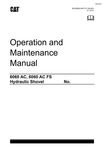
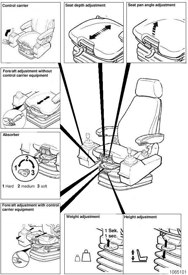
Operator's seat
The operator's seat (Fig. 2-42: and Fig. 2-43:) can be adjusted in several positions.
Never adjust the seat while driving. Concentrate on the road to avoid accidents.
Before carrying out any seat adjustments stop the machine and set the control levers to "0"
Fire extinguisher
The excavator is equipped with two four extinguishers. The conventional one is located near the operators cab (Fig. 2-44:), the carbon dioxide fire extinguishers are located near the electric motor and switching cabinets.
Handling
The excavator operator and the maintenance personnel must informthemselves about how to handle the fire-extinguisher in order to be able to act fast and efficiently in case of beginning fires. Such instruction should be given by a qualified instructor.
Extinguishing agent
The conventional fire-extinguisher is filled with 12 kg (26.4lb) Glutex. This extinguishing agent is used for fighting fires of classes A, B and C. Fires are extinguished fast, perfectly and without residues. The carbon dioxide fire extinguishers are intended for fighting fires of electrical parts.
Pull out securing pin (2, Fig. 2-45:).
Strike knob (3) hard, then release again.
Operate the extinguishing gun.
After fire-fighting, the extinguisher must be refilled Immediately and prepared ready for use.
Inspection
Have the extinguisher inspected at regular intervals by an expert. This is required by local authorities and insurance companies and is in the interest of your own safety.
Have the fire-extinguisher checked at the prescribed intervals by authorized testing agencies.
Automatic fire-extinguishing system (optional)
The automatic fire-extinguishing system prevents fire from spreading.
It is, however, assumed that the machine is thoroughly cleaned of combustible and easily flammable substances.
The excavator operator and the maintenance personnel must familiarize themselves with the automatic fire-extinguishing system.
Such instruction should be given by a qualified instructor.
The fire-extinguishing system is activated automatically in an emergency.
Individual extinguishing circuits can be activated manually.
Inspection
Have the extinguishing system inspected regularly by an expert. This is required by authorities and insurance companies and is in the interest of your own safety.
Trainer's / instructor's seat
For operator training / instructing purposes it is often required that a trainer / instructor accompanies the operator in the cab.
For the safety of the trainer / instructor during excavator operation the cab is equipped with a second seat. This seat is installed behind the operator's seat (Fig. 2-46:).
Sit down on this seat and do not forget to fasten the seat-belt, if installed (arrow, Fig. 2-46:).
Do not leave this seat during the training / instruction session and /or as long as the machine is in operation.
Emergency escape device (optional)
Elements of the harness
(Fig.
2
Important hints
Read and observe the Description of the supplier.
Before using operator shall have received adequate training.
The harness must be used by one person only. He is responsible for the appropriate use and maintenance.
Visual inspection is recommended prior to each use; if necessary it must be checked by an expert. Harness must be checked annualy (every 12 month) by an expert.
Taking on harness
Take harness out of handbag (15, Fig. 2-50:).
Pull loop (6) of the back support (1) between your legs to the front (Fig. 2-52:).
Pull loop (5, Fig. 2-53:) through loop (6).
Take on shoulder belts (2 and 3, Fig. 2-51:).
Pull loop (4, Fig. 2-53:) through loop (5).
Press the hooking safety device (17, Fig. 2-53:) of the snap hook (16).
Pull back support (1, Fig. 2-51:) behind your body (Fig. 2-52:). The loops (4 and 5) are in front of your body.
Hang up loop (4, Fig. Fig. 2-55:) into snap hook (16).
If you have the harness put on in such a way in case of danger you can escape from the excavator (Fig. Fig. 2-57:).
Release hooking safety device (17, Fig. 2-56:).
MONITORING, WARNING AND CONTROL ELEMENTS
(Fig. 2-58:)
BCS, Board-Control-System
No. Element Function Symbol
1 BCS Electronic system for measured data acquisition and processing
Board Control System, acquisition and display of important operating data of the hydraulic shovel.
The surface of the monitor is sensitive to the touch (touch-screen technology). A touchscreen permits selecting menus and programs by touching graphic control symbols and to recall, for instance operating data of the hydraulic shovel.
For further information please refer to section 5 of this Operation and Maintenance Manual, chapter “Board-Control-System”.
2 Monitor BCS
3 Push-button Navigation in menus
The monitor displays collected operating data, warning messages and – if needed –instruction for help.
Control of cursor movements, program selection within the BCS, confirmation of inputs / displayed values (Enter), quitting of menus / sub-menus
4 Push-button Numeric keypad Input of numeric values.


(Fig. 2-59)
BCS, Board Control System, display screen example
(For further information please refer to section 5 of this Operation and Maintenance Manual, chapter “BoardControl-System”).
No. Element Function Symbol
1 Status line
2 Touch-screen Monitor BCS
3 Pushbutton Navigation in menus
Indicates activated functions and operating hours.
The symbols displayed are those of the switches in the control column
Indicates collected operating data graphically and / or numerically, displays warning messages, fault messages and – if needed –instructions for help.
Control of cursor movements, program selection within the BCS, confirmation of inputs / displayed values (Enter), quitting of menus / sub-menus
4 Push-button Numeric keypad Input of numeric values.
5 Touch-screen buttons Examples
6 Status line Fault messages
Displays fault messages as a code number and as plain text. The "Fault" button permits displaying further fault messages stored in the system.
(
No. Element Function Symbol
32 Key-switch
33 Buzzer (inside the control column)
34 Socket connectors
35 Switch Emergency shut-off
Switches the electrical system on and off.
Gives three acoustic warning signals if a fault is reported. The signals appear every 30 seconds.
Connection of electronic devices for fault diagnosis purposes.
De-energizes the outputs of the electronic control units:
The engines are shut off, all valves are deenergized, working movements no longer possible.
(see: "Emergency shut-off function").
(Fig. 2-61:)
All switches and pushbuttons have an illuminated symbol face. The opposite side is equipped with an LED. The LED lights up when the switch / pushbutton is actuated.
No. Element Function Symbol
41 Push-button Electric motor ON Switches on the electric motor.
42 Push-button Electric motor OFF Switches off the electric motor.
49 Indicator lamp Medium voltage Lamp is lit up when the circuit breaker is switched on. Medium voltage 6.6 kV applied.
50 Indicator lamp Rotary field monitoring Lamp is lit up when the rotary field (phasing) is correct.
(Fig. 2-62:)
All switches and pushbuttons have an illuminated symbol face. The opposite side is equipped with an LED. The LED lights up when the switch / pushbutton is actuated. No. Element Function Symbol
61 Push-button Superstructure holding brake Blocks the superstructure.
Press this button when the superstructure is stationary. Do not use this button while the superstructure is still in motion. Risk of damage to the brake and the swing gearboxes.
63 Push-button Hydraulic shovel parking brake, for Service and Maintenance purposes only
Press the switch face with the symbol: The parking brake is applied permanently. The hydraulic shovel cannot be moved. For more information refer to chapter “Track parking brake”.
Actuate this switch only when the hydraulic shovel is stationary. Do not use this switch while the hydraulic shovel is still in motion. Risk of damage to the brakes and the travel gearboxes.
64 Push-button Central greasing system reset
Reset function of the central greasing system control (Press for at least 3 sec.).
Press switch face without symbol: Resets the control of the superstructure. Press the switch face with the symbol: Resets the control of the undercarriage.
65 Push-button Emergency lowering Lowering of the working equipment in an emergency situation. For instance, if the electric motor has failed. For more information refer to chapter “Emergency lowering of the working equipment”.
(Fig. 2-63:)
All switches and pushbuttons have an illuminated symbol face. The opposite side is equipped with an LED. The LED lights up when the switch / pushbutton is actuated.
No. Element Function Symbol
71 Switch Servo-control
72 Switch Travelling speed
Press the switch face with the symbol: The electro-hydraulic servo-control is enabled.
Not actuated: 1st travelling stage travelling forwards / backwards is possible
Press the switch face with the symbol: 2nd travelling stage, only parallel forward travel is possible. in case of backward travel and cornering, the machine switches back automatically into the 1st travelling stage.
76 Push-button When the machine has to be manoeuvered out of dangerous situations
Press the switch face with the symbol: The machine can be driven and the superstructure be swung although these functions are automatically deactivated. Use this function only in dangerous situations to manouever yourself or the machine out of hazard zones. Risk of damaging parts of the machine, e.g. the hydraulic ladder or the tanklift.
81 Switch Floodlamps
82 Switch Lighting
83 Switch Lighting
84 Switch Rotary beacon (option)
Switches all floodlamps on and off.
Press the switch face with the symbol: Switches on the lights in the operator's cab.
Press the switch face with the symbol: Switches on the maintenance lights in the modules.
Press the switch face with the symbol: Rotary beacon ON.
(Fig. 2-64:)
All switches and pushbuttons have an illuminated symbol face. The opposite side is equipped with an LED. The LED lights up when the switch / pushbutton is actuated.
No. Element Function Symbol
91 Push-button Dumper count
Press the switch face with the symbol: Resets the loaded dumper count.
92 Switch Windscreen wiper Press the switch face with the symbol: Windscreen wiper in intermittent operation mode.
Press the switch face without symbol: Windscreen wiper in permanent operation mode.
93 Pushbutton Windscreen washer
94 Switch Preheating (optional)
96 Switch Cable reel (optional)
Press the switch face with the symbol: Windscreen wiper in wipe/wash operation.
Switches the preheating system on and off.
Switches the cable reel system on and off.
(Fig. 2-65:)
No. Element Function Symbol
101 Push-button (Free for options) Can be used as a push-to-speak button on a radio, or to switch over from one camera to another one.
102 Push-button Stick floating position (shovel equipment only)
Button is pressed: The stick cylinders are pressurized on retracting.
Press button (102) only in position "0" of control lever (115).
103 Push-button Boom floating position Button is pressed: The boom cylinders are pressurized on retracting.
Press button (103) only in position "0" of control lever (116).
104 Push-button Warning signal Button is pressed: Acoustic warning signal / horn is activated.
105 Push-button inside the seat Electronic hydraulic shovel control (servo-control)
The electronic hydraulic shovel control (servo-control) is activated when the operator sits down on the seat. The electronic hydraulic shovel control (servo-control) is deactivated when he leaves the seat. 111
Shovel trap (shovel equipment only)
Forwards – shovel trap is opened; Backwards – shovel trap is closed.
115 Control lever
Forwards – raising the stick
Backwards – lowering the stick.
To the left / right –swinging and braking of the superstructure. 116 Control lever Forwards – lowering the boom; Backwards – raising the boom.
To the left – backwards tipping of shovel / bucket;
To the right – dumping of shovel / bucket. 117 Push-button
118 Thumb wheel Shovel trap (shovel equipment only)
119 Push-button By-pass for the automatically switch off for stickand /or backhoe cylinders (Option)
120 Thumb wheel
Not used on this machine.
Turn Forwards – shovel trap is opened; Turn Backwards – shovel trap is closed. Function can be overridden by Pedal 111. (Thumb wheel is spring centered).
Lower half pushed – automatically stopped stick- and/or backhoe cylinders can be driven slowly to the limit stopps.
Upper half pushed – Each press on the button increments the loaded dumper count for by "1". (Count reset with button (91)).
Not used on this machine.
(Fig. 2-66:)
Optional equipment: Air conditioning (Depending on the options ordered with the machine, the described elements can be found on different positions on the control column).
No. Element Function Symbol
150 Rotary switch Fan (Air conditioner)
151 Knob Thermostat (Air conditioner)
152 Rotary switch Mode (Air conditioner)
Selects the intensity level of the blower (3 levels).
Sets the desired temperature inside the cab.
Selects the desired control function (heating, cooling, ventilation, defrosting).
Putting The Machine Into Operation
Before daily start-up, carry out works in accordance with servicing plan T (see Part 3 "Inspection and servicing")
Prior to your dailiy start-up, make sure the machine has been cleaned of combustible and easily flammable substances.
Otherwise, increased fire and explosion hazard will exist.
Service station (tanklift)
The excavator is equipped with a central service station (Fig. 2-67:). The service station is attached to the frame and accessible from the ground below the uppercarriage. Express couplings are provided for refilling the following consumables (fluids).
Pos. Fig. 2-67:
Fluid Express coupling for
5 Gearbox oil for pump drive gearbox Filling and / or draining
10 Hydraulic oil Filling and / or draining
11 Grease for the central greasing system Filling
A service vehicle is needed for filling and/or draining of the fluids.
Lowering the service station
Draw out control knob (21, Fig. 2-67:) of valve (22) with rope (25). The service station is brought down to the lower position. Turn knob (21) by 90° and engage.
Raising the service station
Disengage control knob (21) of valve (22), turn by 90° and press in. The service station is raised to the top position.
Refilling and draining
For filling in or for draining fluids, unscrew the cap of the corresponding express coupling (Fig. 2-67:). Attach express coupling of filling hose from the service vehicle to the corresponding express coupling at the service station. Fill in or drain off fluid. Take off filling hose and refit cap on the express coupling.
Assemblies resp. reservoirs Measuring device
Remarks
Pump drive gearbox Dipstick (1, Fig. 2-68:) Stop filling when the oil reaches the "max" mark on the dipstick (see Part 3, chapter "Pump drive gearboxChecking the gearbox oil level/Filling in oil").
Hydraulic oil tank BCS monitor (Fig. 2-71:), Inspection glass (1, Fig. 2-69:), sign (2. Fig. 2-69: and Fig. 2-70:)
Checking the oil level:
Extend the piston rods of stick and bucket cylinders halfway and stand working equipment on the ground (as shown on sign 2, Fig. 2-70:).
Check oil level at an oil temperature of ca. 50 °C (122°F), with the electric motor shut off.
Fill in oil when the oil level in the inspection glass hasdropped below the "min" mark. Stop filling if the oil reaches the "max" mark on the inspection glass or the acoustic warning signal "Travel alarm" sounds (see chapter "Hydraulic system - Checking the hydraulic oil level / Refilling hydraulic oil").
Assemblies resp. reservoirs Measuring device Remarks
Grease container – cental lubricating system
BCS display (Fig. 2-71:)
BCS display indicates a warning when the grease container is empty.
Fill in grease using express coupling (11, Fig. 2-72:). Switch on the display system with the toggle switch (23, Fig. 2-72:). Monitoring lamp (22) lits up.
Stop filling when BCS indicates "Grease container filled". The indicator lamp (24) lights up.
On completion of filling, switch the display system off again with the toggle switch (23). Monitoring lamp (22) is then off.
Battery main switch, switching on and off
When the excavator is disconnected from the medium voltage (6.6 kV) the electrical system (24V) is supplied with voltage by two batteries. With the battery main switch, the electrical system (24V) is disconnected from the batteries.
The battery main switch is located at the left side wall of the control cabinet (24V). The control cabinet (24V) is mounted in the operator's cab module beneath the operator's cab.
Switching the battery main switch on
Turn switching handle of main switch (1, Fig. 2-73:) to position "ON".
Switching the battery main switch off
Turn switching handle of main switch (1. Fig. 2-73:) from position "ON" to position "OFF"
The handle can be locked in the "OFF" position by means of a padlock.
Electrical system (24V), switching on and off
The electrical system is switched on or off with key-switch (32, Fig. 2-74:).
Switching the electrical system (24V) on
Insert key into key-switch (32) and turn to the right.
Now all electronical assemblies of the excavator are supplied with voltage, computer systems are started. A selftest is carried out.
The Board Control System (BCS) displays current operating data as well as detected faults.
If there are no critical faults detected BCS enables starting the electric motor.
If there are critical faults or failings detected BCS disables starting the electric motor and displays corresponding explanatory text.
For more information see " Operation and Maintenance Manual Board-Control-System".
Switching the electrical system (24V) off
Turn key in key-switch (32) to the left and withdraw
Switching the electric motor on and off
Before switching on the electric motor
Before switching on the electric motor, check that nobody is working on the electrical system or on the excavator itself.
Switch on the electric motor only when all these work on the excavator is finished and all persons leave the danger area.
Switch on battery main switch (see: "Battery main switch, switching on and off").
Switch on electrical system (24V) (see: "Electrical system (24V), switching on and off").
Check telltales (49 and 50, Fig. 2-75:), they must lit up in green colour. If so, electric motor can be switched on (see: "Switching the electric motor on").
If telltales didn`t lit up in green colour, BCS has detected critical operating conditions or faults which prohibit starting the electric motor. BCS indicates this case with telltales as well as by displaying corresponding text.
Switching the electric motor on
Actuate switch-key (41, Fig. 2-76:), the electric motor is switched on.
During starting period the electric motor heavily warm up. Therefore it is not allowed to switch it on and off at will. By means of an electronical time-out circuit (PLC) the electric motor can be switched on only three times a hour (time-out period is 30 minutes).
Switching the electric motor off
During breaks in operation and at the end of each shift, the working equipment must be lowered onto the ground.
The electric motor must NOT be switched off until the equipment is resting on the ground.
To avoid straining the vacuum contactor, the electric motor should be shut down only when load-free, i.e. without any of the hydraulic units being activated at the same time via the control valve.
Actuate switch-key (42, Fig. 2-77:). The electric motor starts running down.
Turn key in key-switch (32) counter-clockwise and withdraw.
The control voltage is switched off.
The electric motor only can be switched on again, after the time-out period (30 minutes after last switching on) is over (see: "Time-out before restart", "Before switching on the electric motor" and "Switching on the electric motor").
Time-out before restart
During starting period the electric motor heavily warms up. Therefore it is not allowed to switch it on and off at will. By means of an electronical timeout circuit (PLC) the electric motor can be switched on only three times a hour (time-out period is 30 minutes).
The 30 minutes period means the time from switching on the electric motor up to the next switching on, e. g.
Electric motor is switched on, runs 20 minutes and then is switched off. Now the time-out period is 10 minutes before restart.
After running more than 30 minutes without interruption the electric motor can be switched on without any time-out period.
The eCAMP system prohibits switching on the electric motor until it is cooled down.
The BCS monitor (Fig. 2-78:) displayes the remaining time until the time-out period is over.

Electric motor can not be switched on
If BCS prohibits switching on the electric motor the operator should check the following:
Time-out before restart period still running?
EMERGENCY STOP switch in control column unlocked?
EMERGENCY STOP switch in control cabinet (400V) unlocked?
EMERGENCY STOP pullswitch near the service station unlocked?
Servicing switch unlocked?
Monitoring lamps "6.6 kV OK" and "PHASE SEQUENCE OK" on the control cabinet (400V) and on the control column lighting? If not, the circuit breaker is switched off or the 6.6kV voltage supply is missing.
Shut-off flaps at the hydraulik oil reservoir closed?
Check BCS display: Faults or explanatory text displayed? If so, give information to the electric maintenance personnel.
If after all of these checks the electric motor cannot be switched on the operator has to inform the specialist personnel for maintenance and service on electric excavators. Only these have the skills to work in a safe way, for trouble shooting and removing the fault.
In case of failure
If failures in the electrical systems occur, BCS displayes warnings and corresponding explanatory text
Failures in electrical systems may exclusively be removed by specialist personnel for maintenance and service on electrical systems. The following faults may be responsible:
fault in high-voltage transformer
6.6 kV/ 400V/ 230V transformer overloaded.
earth fault.
If BCS display shows "Overcurrent", the operator does not know if an "Earth fault" happens. In worst case the excavator may be energized.
The operator must notify the electrician in charge from the excavator superstructure.
The electrician must then cut off the voltage supply from the transformer station and locate and rectify the fault.
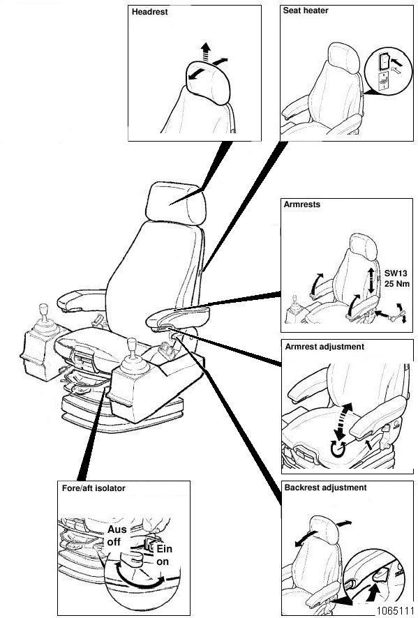
Circuit breaker, switching on and off
By means of the circuit breaker the supplied medium voltage 6.6kV can be connected to the excavators electrical system or can be disconnected from it. The circuit breaker is installed in the control cabinet 6.6 kV (outer view, Fig. 2-79:, inside view Fig. 2-80:).
Switching the circuit breaker on is possible only when the eCAMP system and the motor protection relay enable this function. In this case, all four monitoring lamps (1, Fig. 2-80:) light up in green colour.
The circuit breaker is operated with an actuating lever which is stored in a fixture inside the control cabinet 6.6 kV.

Switching the circuit breaker
The circuit breaker is switched on and off by means of a actuating lever (Fig. 2-81:). The actuating lever is slipped over the actuating shaft of the circuit breaker.
Detailed information is given in the brochure of the manufacturer “Medium-voltage switching devices”. See volume “Components” of the printed machine documentation.
Motor protection relay, functions
The electric motor is equipped with a motor protection relay. The relay is located in the 400 V switch cabinet (Fig. 2-82:).
The relay monitors the operating conditions of the electric motor and protects the motor against faults in the electrical system of the motor
Depending on the nature of the fault, the motor protection relay switches off
the power supply of the motor via the vacuum contactor or
the power supply of the machine via the switch-disconnector.
At the factory, the motor protection relay is programmed for the following functions:
protection against overcurrents,
protection against overloading,
detection of ground faults,
temperature monitoring,
restart inhibit,
protection against undervoltage,
protection against load unbalance (failure of a phase)
phase sequence monitoring,
change of frequency,
run-up period monitoring.
In case a severe fault of the motor system is detected in operation, the motor protection relay is activated and the electric motor shut off automatically. If the motor protection relay detects a severe fault before or during the starting sequence of the electric motor, it prevents the motor from being started. Depending on the type of fault detected, one or more LEDs on the front panel light up (9, Fig. 2-83:).
After rectification of the fault press button (7). The LED is extinguished. The motor protection relay is again operational.
For more information please refer to the the manufacturer's description.
Front panel control and monitoring elements
(Fig. 2-83:):
1 RUN indicator (LED)
2 Display screen (provides information on states of operation)
3 Display screen navigation keys
4 Function key freely programmable (not used for this machine)
5 Control of other equipment (not used for this machine)
6 USB interface for communication with external devices (only for CGM HMS GmbH Service)

7 Reset for LEDs of item 9.
8 Cover for keypad of item 4.Functional description of the LEDs of item 9.
9 LEDs G1 – G8, on after detection of a fault: G1 – Overcurrent
G2 – Undervoltage/overvoltage
G3 – Load unbalance
G4 – Frequency change
G5 – Overload
G6 – Phase sequence fault, ground fault
G7 – Run-up monitoring, restart inhibit
G8 – Emergency STOP activated
For more information please refer to the the manufacturer's description.
Air conditioner (optional)
Ventilation / Heating
The air needed for ventilation and/or heating is sucked in from outside the cab by a blower and ducted to the air outlets.
If necessary, the air in the cab is sucked in through the air conditioner and recirculated.
The air conditioner control elements are located at the left side of the control column (Fig. 2-84:).
Do not switch the air conditioner to "cooling“ when the back-up heating (optional) is on.
Back-up heating operator’s cab (optional)
The back-up heating for the operator’s cab is located in the module below the operator’ cab (Fig. 2-85:). The heating consists of one or two heating units (1) and the fuel reservoir (2).
Switch on the back-up heating using switch (142, Fig. 2-86:). The pilot lamp above switch (142) lights up.
The heating system has an automatic regulation.
Do not switch on the back-up heating when the air conditioner is set to ”cooling”.
Control panel (SIGMA)
(see Fig. 2-84:)
1 Rotary switch Selects the intensity level of the blower (3 levels).
2 Rotary switch Selects the desired control function (heating, cooling, ventilation, defrosting).
3 Thermostat Sets the desired temperature inside the cab.
TRAVELLING, SAFETY INSTRUCTIONS
Have the attachment raised only so far as to permit the machine to be driven under overhead power lines without any risk. Close the cab door.
If the machine is fitted with a safety belt for the operator, fasten the belt.
If the superstructure is turned by more than 90° from the BASIC POSITION, the excavator travels in the opposite direction to that selected.
If the position of the superstructure in relation to the undercarriage is not exactly known, touch the accelerator lightly to see which direction the machine takes, before initiating the full travelling movement.
Warn persons in the immediate vicinity by sounding the horn before setting off. Never drive across slopes.
Take the utmost care on slippery, greasy ground. If the machine is to be driven a longer distance, the superstructure must be secured against turning by means of the superstructure holding brake.
Running-in specifications for components of the crawler tracks
Prior to initial commissioning and/or after repair work, run in the idlers, track rollers and support rollers as follow:
Raise the equipment (Fig. 2-87:) or (Fig. 2-88:).
Drive the excavator in revers approx. 50 m / 164ft.
Drive the excavator in forwards approx. 50 m / 164ft.
Stop the excavator.
Measure the temperature at each dler, track roller and support roller with an infrared thermometer (at a temperature of approx. 100° C / 212°F wait for idlers, track rollers and support rollers to cool down).
Repeat this running-in procedure up to 10x.
Check all idlers, track rollers and support rollers for leaks.
Trailing cable
Never touch the trailing cable. Risk of voltage drive, if the trailing cable insulation is defective!
Change the position of the trailing cable only by means of a cable hook.
TRAVELLING Superstructure basic position
Travel direction and sense of actuation of pedals (112 and 113, Fig. 2-90:) are identical only when the excavator is in its BASIC POSITION (Fig. 2-89:).
Travelling forwards/backwards
Travelling forwards: depress pedals (112 and 113) forwards, the excavator travels in the direction of the idler (2, Fig. 2-89:).
Travelling backwards: depress pedals (112 and 113, Fig. 2-90:) backwards, the excavator travels in the direction of the drive sprocket (4, Fig. 2-89:).
During travelling an acoustic warning sounds (Travel Alarm).
If the superstructure is swung out of its basic position by more than 90° (Fig. 2-91:), the excavator moves in a direction opposite to that expected w hen pedals (112 and 113, Fig. 2-90:) are depressed.
The pedals return automatically to their "0" positions when released.
Reverse the excavator only over short distances and with the assistance of marshallers because of restricted rear-view conditions. Do not travel across slopes.
When travelling uphill or downhill, the travel drive must always be at the rear. Travel only in the basic position of the excavator and only forwards. Be extremely careful on slippery and greasy ground.
All instructions with regard to travelling speed regulation and travel direction control are applicable only as long as the crawler tracks have sufficient grip and do not slip.
If the operator is not completely sure of the position of the superstructure with regard to the undercarriage, pedals (112 and 113) should be depressed slightly in order to find out which way the excavator moves before initiating the full travelling movement.
Regulating the travelling speed
Travelling on level ground:
Regulate the travelling speed with
pedals (112 and 113, Fig. 2-92:)
set the first (slow) range or the second (fast) range with switch (72, Fig. 2-93:).
Change speed range only when the excavator is stationary.
Travelling uphill and downhill
Read and observe the "TravellingSafety instructions" chapter.
Depress padals (112 and 113, Fig. 2-92:) fully to the limit stop.
When travelling downhill, the travel retarder valve acts as a speed limiter.
The travel retarder valve works correctly if pedals (112 and 113) are fully depressed down to the limit stop.
Should the travelling speed become too high when travelling downhill release pedals (112 and 113) to stop the excavator.
Cornering
To take a right-hand corner forwards:
depress only pedal (112, Fig. 2-94:) forwards.
To take a lefthand corner forwards:
depress only pedal (113) forwards.
Turning
To turn to the right:
depress pedal (112) forwards and pedal (113) backwards.
To turn to the left:
depress pedal (113) forwards and pedal (112) backwards.
Never use the working equipment to raise one side of the undercarriage and then turn the undercarriage by initiating the swing and/or the travelling function.
This way of working is contrary to the excavator'sdesignated use.
There is a risk of accident. Moreover, the tracks, swing gear, roller bearing swing ring, backhoe or bucket back-wall and the front part of the bucket are subjected to inadmissibly high stresses.
Note
Change the position of the undercarriage - parallel or perpendicular to the working face - only by cornering forwards/backwards (Fig. 2-95:).
Cornering to the left: forwards from pos. 1 to pos. 2 backwards from pos. 2 to pos. 3 forwards from pos. 3 to pos. 4
The same procedure should be adopted if the excavator is to be driven out of depressions (Fig. 2-96:):
Cornering to the left from pos. 1 to pos. 2
Cornering to the right from pos. 2 to pos. 3
Travelling over long distances
Travel only forwards with the excavator in its basic position.
Travelling backwards over longer distances could damage parts of the undercarriage.
Read and observe the "Travelling –Safety instructions" chapter.
When travelling, pay attention to sufficient headroom, e. g. under cable bridges or high-tension cables.
Keep the loading or the backhoe bucket close to the ground. For a more uniform loading of the tracks, the equipment must, however, be kept at a steep angle (Fig. 2-97: / Fig. 2-98:).
Loading bucket equipment (Fig. 2-97:):
Fully extend boom cylinder (1),
retract bucket cylinder (2),
retract stick cylinder (3) to such an extent as to reach the position of the working equipment (Fig. 2-97:).
Backhoe bucket equipment (Fig. 2-98:)
Fully extend boom cylinder (1),
extend backhoe cylinder (2),
extend stick cylinder (3) to such an extent as to reach the position of the working equipment shown in (Fig. 2-98:).
Lower the equipment when travelling underneath obstacles.
If the equipment position must be changed:
stop the excavator,
change the position,
continue to travel.
After travelling for 15 minutes without interruption, stop the excavator and check the temperatureof the track rollers.
If the temperature does not exceed ca. 100° C / 212°F, continue travelling.
In case of higher temperatures:
Stop travelling. Resume travelling only after the track rollers have cooled down to ca. 40° C / 104°F.
Superstructure holding brake
The excavator is equipped with four superstructure holding brakes. The superstructure holding brakes are used to block the superstructure and the undercarriage.
The superstructure holding brakes are parking brakes.
Do not actuate the switch unless the superstructure is stationary. Do not use this switch while the superstructure is still in motion. Risk of damage to the brakes and the slewing gears.
To activate the holding brakes, press switch (61, Fig. 2-99:):
when the excavator is parked,
when travelling over longer distances.
Track parking brake
The hydraulic shovel is equipped with four travelling gear brakes which are integrated in the travel drives.
The travelling gear brakes are parking brakes. They protect the hydraulic shovel from rolling forwards or backwards. When the machine is parked, travel brakes are activated automatically. The brakes are deactivated during operation of the machine.
Note:
As travel brakes are deactivated, machine could slightly move in direction of excavating during operation.
Whenever loading operation is interrupted, stand working equipment on the ground. This avoids slight movement of the machine and possible consequential damage of lowered ladder, in case ignition remains engaged.
For Service and Maintenance purposes the travelling gear brakes can also be applied with switch (63, Fig. 2-100:).
Actuate this switch only when the hydraulic shovel is stationary. Do not use this switch while the hydraulic shovel is still in motion. Risk of damage to the brakes and the travel gearboxes.
Press the switch face with the symbol (63): The parking brake is applied permanently. The hydraulic shovel cannot be moved.
For more detailed information refer to the Service Manual, chapters eight and nine.
TRANSPORTING THE MACHINE Transport - Safety instructions
The machine must be loaded and transported only after all safety regulations have been observed and complied with.
Entrust loading and transporting of the machine to a company experienced in the transport of heavy equipment.
The responsability for loading and transporting lies with the transport company or their representative.
Remove oil, grease, soil, mud, snow, ice and other materials from the excavator's crawler tracks and from ramps and loading platforms of the transport vehicle to minimize slipping.
Secure the transport vehicle against rolling away. Use only tying equipment of sufficient strength (the weights and dimensions of the excavator are set out in the "Technical specifications").
Transport
The dimensions and the service weight of the fully assembled excavator do not allow the excavator to be transported in an undismantled state on a lowbed trailer over public roads.
Therefore, the following components and modules must be dismantled beforehand.
Suspensions points as well as the center of gravity are marked on the modules (see example, Fig. 2-101:).
Dimensions and weights of the machines modules can be found in the annex, chapter “Product Specification Sheet” as well as in the “„Service Manual“”.
Detailed instructions for disassembling and assembling the machine can be found in the Service Manual.
WORKING OPERATION - SAFETY INSTRUCTIONS
Read the sections "Fundamental safety instructions" and "Operation, safety instructions" carefully and observe the instructions given in them.
Inspect the site for underground gas, power and water lines before starting work. Any damage to such lines is a risk to life!
Clean off any earth, mud, snow, ice, grease and oil adhering to your working footwear before operating the machine. There is otherwise a risk of slipping off the pedals and initiating inadvertent movements.
Sound the horn to warn persons in the immediate vicinity before starting work.
Stop work if anyone is in the hazard range of the machine. Make sure they have left the hazard range before resuming work.
Never operate the machine unless it is standing on a reasonably horizontal, flat surface. The stability of the machine is otherwise at risk.
Ensure that the attachment has adequate clearance below overhead power lines and structures. Trenches and working faces may give way. Keep well clear of them.
Do not operate the machine,
when several track rollers or support rollers have been removed;
when one or several slewing gearboxes have failed or been removed;
when one or several teeth on the backhoe or on the shovel are worn or missing;
when parts of the hardfacing layer on the backhoe or on the shovel are worn or missing.
Working under these circumstances results in heavy wear and possibly in severe damage and thus in high repair costs.
Such circumstances are considered by CGM HMS GmbH GmbH as "abusive utilization".
CGM HMS GmbH GmbH refuses to assume the guarantee for damage and consequential damage caused by an abusive utilization of the machine.
Running-in instructions for hydraulic cylinders
Compression of an oil/air compound in a hydraulic cylinder may result in detonations which might damage pistons and sealing rings.
Prior to initial commissioning and/or after repairs, run in the hydraulic cylinders as follows:
Switch on the electric motor.
The pressure-limiting valve in the hydraulic system must not respond
In the first two working cycles, retract and extend the pistons of the hydraulic cylinders to max. ½ to ¾ (not to the limit stop).
Never change direction suddenly. The waiting time between changes of direction must be at least 4 seconds.
In the next eight working cycles, retract and extend the pistons of the hydraulic cylinders to the limit stop. The waiting time between changes of direction must be at least 4 seconds.
When all hydraulic cylinders have been run in, the excavator can operate at a higher engine speed.
Avoid extreme positions of the attachment
Parts of the attachment may damage the machine if they are moved into extreme positions (see illustrations Fig. 2-102: - Fig. 2-106:).
Work carefully, avoiding extreme positions of this kind.
WORKING OPERATION Before starting work
Prior to initial commissioning and after repairs on the central lubricating system or the hydraulic cylinders, move the unloaded equipment for abt. 5 minutes.
This is required to ensure an adequate supply of grease to the cylinder bearings when the work starts.
Warming up
At low outside temperatures it is necessary to run the hydraulic system up to operating temperature. The temperatures at which warming up is necessary depend on the type of hydraulic oil used; see also "Oils for hydraulic systems".
Switch on the electric motor and start to perform no-load working movements for abt. 10 minutes with the excavator.
Activating the electronic servo control
The hydraulic shovel can execute working movements only after the electronic servo control (pilotcontrol) has been activated.
The servo-control block is enabled by switch (71, Fig. 2-107:).
At the beginning of the work, the electronic servo control (pilot-control) is activated by a contact in the operator's seat (105):
Electronic servo control ONThe operator is sitting on his seat.
Electronic servo control is OFFThe operator's seat is empty.
Note:
During operation it is absolutely necessary that the operator keeps sitting on his seat. Otherwise working movements may be interrupted suddenly: risk of damaging the holding brakes and the gearboxes.
Swinging the superstructure
Swinging of the superstructure is possible onlywhen:
the superstructure holding brake is released and
the hydraulic shovel operator is sitting on his seat and
the hydraulic ladder is raised and
the servicestation (tanklift) is raised and
the BCS swing circuit test was successful.
To swing the superstructure to the rightmove control lever to the right (115, Fig. 2-108:).
To swing the superstructure to the leftmove control lever to the left (115).
After releasing, the control lever returns automatically to position “0”.
Releasing the control lever (115) is not sufficient to brake the superstructure automatically. In order to brake the superstructure, the control lever must be moved in the direction opposite the swinging movement (reversing).
Braking the superstructure
The superstructure can only be braked by moving control lever (115) in the direction opposite the swinging movement (reversing).
The superstructure does not stop automatically by simply releasing the swing control lever (115).
To brake the superstructure, the swing control lever (115) must be moved in opposite direction.
In an emergency, activate the holding brake by pressing switch (61, Fig. 2-109:).
Working
When released, all control levers for working operation return automatically to position “0”.
Sound the horn to warn persons in the immediate vicinity before starting work.
Do not exceed the maximum machine inclination (see “Maximum machine inclinations, information” chapter).
Level a surface only in the bucket’s digging direction. Never “beat” or “sweep” with the bucket.
Do not level off a surface with the front shell of the bucket open.
Close bucket completely before beginning to dig.
Extending and retracting the bucket or backhoe bucket stick
To extend the stick: push control lever (115, Fig. 2-110:) forwards.
To retract the stick: pull control lever (115) backwards.
To retract the stick with pressure: (only on bottom-dump bucket equipment) depress button (102) and push control lever (115) backwards.
Opening and closing the bottom-dump bucket
To open the bucket: press pedal (111, Fig. 2-110:) forwards or turn thumb wheel (118) forwards.
To close the bucket: press pedal (111) backwards or turn thumb wheel (118) backwards. Pressing pedal (111) overrides turning the thumb wheel (118).
Raising and lowering the boom
To raise the boom: pull control lever (116, Fig. 2-111:) backwards.
To lower the boom: push control lever (116) forwards.
To lower the boom with pressure: depress button (103) and push control lever (116) forwards.
Filling
And Emptying The Bucket Or The Backhoe
To fill/tip back the bucket: shift control lever (116, Fig. 2-111:) to the left.
To empty the bucket by dumping/tipping: shift control lever (116) to the right.
Emergency lowering of the working equipment
With the electric-motor not functional, the working equipment can be lowered to the ground as follows:
Sit down on the operator’s seat. Switch inside seat (105, Fig. 2-112:) is activated then.
Switch on the electric system with key-switch (32).
Operate switch (71), hydraulic servo system is activated then.
Operate switch (65, Fig. 2-113:) and hold.
Push control lever (116) forwards to lower the working equipment to ground.
Contact the responsible service personnel as soon as possible.
After daily operation
Parking the machine
Park the machine on level and stable ground. This is particularly important in winter to avoid freezing of the tracks.
Stand the working equipment on the ground.
Switch off the electric motor.
Shift both control levers into all directions todepressurize the hydraulic cylinders.
Withdraw the key from the electrical systemkey-switch.
Set the battery main switch to OFF.
Close the cab windows.
Lock the cab doors and all lockable hatches and covers on the machine.
Clean the machine of coarse dirt as well as of combustible and easily flammable substances, if possible with a stream jet (rubber parts and electric components with compressed air – refer to information label). Otherwise, the fire and explosion hazard will exist.
Inspect the hydraulic system, the track rollers, support rollers, idlers and gearboxes visually for leaks.
Escaping oil pollutes the environment.
Repair leaks immediately (or have them repaired).
Report oil accidents to the responsible person.
Check the superstructure, undercarriage and the working equipment for damage and all steel components for cracks or fractures.
Report detected damage immediately to the responsible person.
Clean off gross dirt, ice and snow from the fins and the fan wheel of the hydraulic oil cooler.
ASSEMBLING WORKING EQUIPMENT – SAFETY INSTRUCTIONS
Personel
Assembly work may be carried out only by operating or maintenance personnel who have the necessary know-how at their disposal. If such know-how is lacking, meticulous instruction must be given by experienced personnel, e.g. from CGM HMS GmbH .
The operating manual, and in particular the section headed “Fundamental Safety Instructions”, must have been read and understood.
Only such persons may start up the machine during assembly work in order to adjust the attachments.
Incorrect operation of the machine or the attachments may give rise to life-threatening situations.
Personal protective gear and working clothes
Wear closely fitting working clothing when working on the machine. Loose, wide garments may catch on machine parts and result in injury. Wear your personal protective equipment: a safety helmet, safety goggles, safety footwear and gloves.
When carrying out work on the working equipment, f.ex. on the monobloc boom (Fig. 2-114:), use a fall arrester. Falling down from great hight may cause severe injuries. Connect the fall arrester to the safety line on the boom (arrow, Fig. 2-114:).
Tools and auxiliaries
Tools, hoists, slings, trestles and other devices must be in a reliable, safe state.
Metal splinters may cause injury when accessory bolts are being driven in or out. A brass or copper mandrel should therefore be used for this purpose, and goggles must be worn.
Use only the steps, platforms and handrails when climbing onto or off the machine.
Always keep steps and platforms in a non-slip state. Remove any oil, grease, earth, clay, snow, ice and other foreign matter immediately.
Securing the working equipment
Stand working equipment on the ground in such a way that no movements can be made if mechanical or hydraulic connections become detached. Secure any equipment or component which is to be mounted or dismantled, or whose position is to be changed, with hoists or appropriate slinging/supporting devices to prevent them from moving, slipping or falling inadvertently.
Securing the machine
Carry out work on the attachment only if the machine is secured as described in the “Securing the machine” section.
Selecting the attachments
The machine can be equipped with various attachments. The components of the attachments are assembled with hydraulic cylinders and connectors. Components can be combined in various ways for optimum adaptation of the attachments to the specific application.
Operate the machine only with the equipment and component combinations expressly approved by CGM HMS GmbH for this type of machine.
Never install and commission other equipment and component combinations without CGM HMS GmbH first having inspected and approved the project in writing.
Protective roof against falling objects
The machine is equipped with an integrated cabprotection roof (FOPS).
Securing the machine Risk of injury
The machine must not be started by unauthorized persons.
Therefore, secure the machine. Observe the accident prevention regulations. Depressurize pipeline systems, on which work is to be carried out, by appropriate measures.
Protective shrouds of moving machine parts may only be opened or removed when the drive unit is stationary and protected against inadvertent starting.
Before carrying out fitting works, the machine and the equipment must be protected against inadvertent starting by placing chocks under the tracks and by standing the working equipment on the ground.
Hydraulic and lubricating systems
Close all open bores, pipe and hose connections with pressure-resistant plugs. Refill collected hydraulic oil back into the hydraulic system only through the return-flow filters. Dispose of non re-usable oils without polluting the environment.
All components of CGM HMS GmbH machines have been carefully purpose-coordinated. Troublefree operation and a long service life can only be achieved with original CGM HMS GmbH spare parts.
Respect the sequence of working operations when fitting or replacing the attachments. The sequence has been determined and tested by qualified experts.
Secure the machine as described below:
before carrying out any fitting and modification work on the working equipment,
before carrying out any servicing and repair work on the machine.
Park the machine on level and stable ground.
Stand the working equipment on the ground.
Switch off the electric motor.
Depressurize the hydraulic system.
Withdraw the key from the key-switch.